Loading ...
Loading ...
Loading ...
17
75D2525
DVM Series Direct Vent Gas Fireplace
x
When installed as a rear vent unit this appliance may be
vented directly to a termination located on the rear wall
behind the appliance. Only an MHSC brand termination
is allowed for this application.
• The maximum horizontal distance between the rear
of the appliance and the termination is 20" (508 m).
Figure 14.
• Only one 45° elbow is allowed in these installations.
20"
Maximum
DVR584
Figure 14 -
Rear Vent Application,
Maximum Horizontal Distance
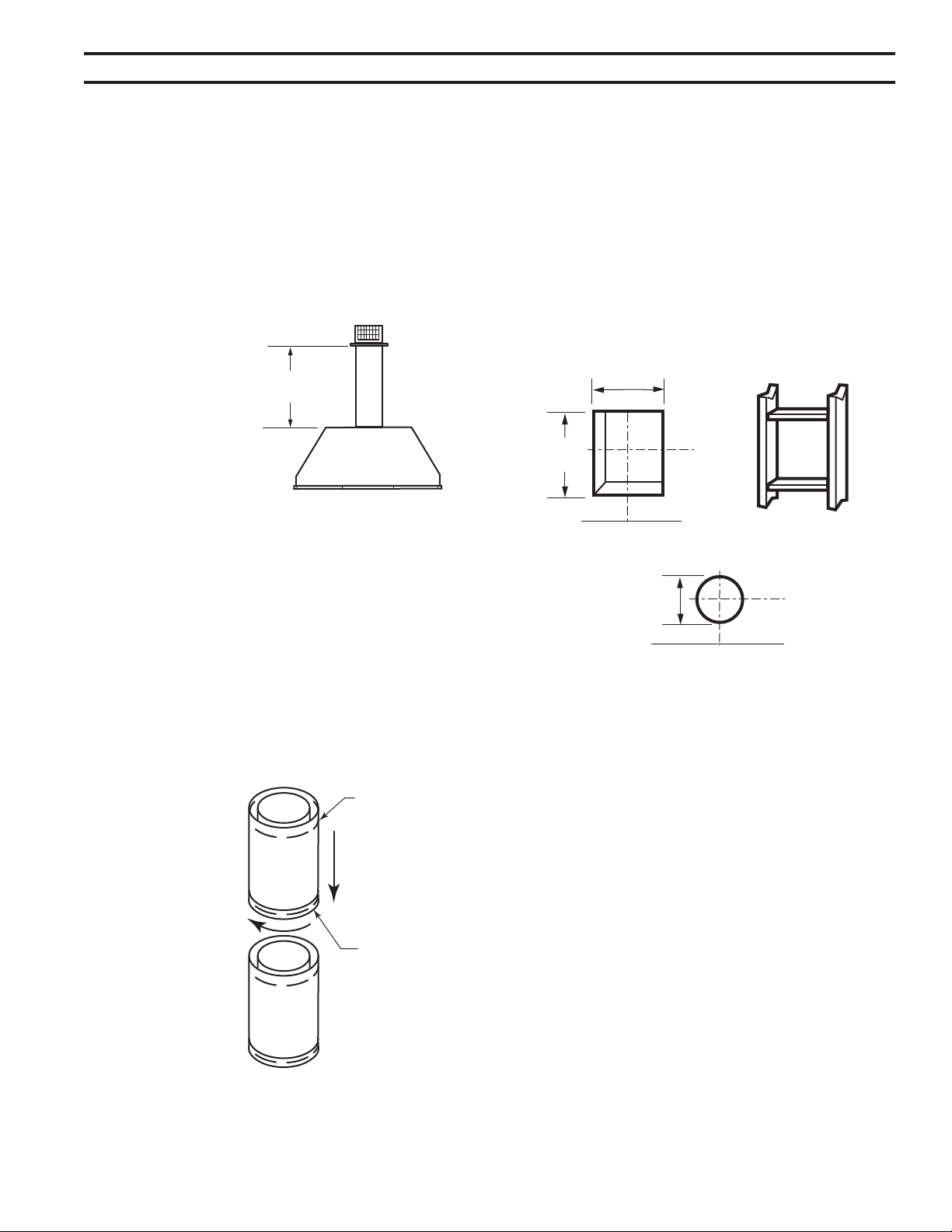
1. Rigid vent pipes and ttings have special twist-lock
connections. Assemble the desired combination of pipe
and elbows to the appliance adapter.
The female ends of the pipes
and ttings have three locking lugs (indentations).
These lugs will slide straight into matching slots on
the male end of adjacent pipes and ttings. Push the
pipe sections together and twist one section clockwise
approximately one-quarter turn until the sections are
fully locked. Figure 15
Female
Locking Lugs
Male Slots
FP1953
2. Refer to the venting and termination instructions for
further instructions.
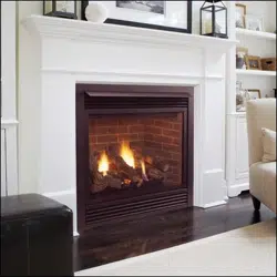
3. Locate and cut the vent opening in the wall. For com-
bustible walls rst frame in opening.
Cut a 12Z\x"H x 10Z\x" W
(318 x 267 mm) hole through the interior wall.
Cut a 10Z\x"H x 10Z\x"W
(267 x 267 mm) square hole through the exterior
wall frame. Figure 16
Hole opening should be 8Z\x"
(216 mm) in diameter.
4. The center of the hole should align with the center line
of the horizontal rigid vent pipe end. Allow 1/4" minimum
rise per foot. Figure 16
5. Apply a bead of non-hardening mastic around the
outside edge of vent cap. Position the vent cap in the
center of hole on the exterior wall with the word “UP”
on the vent cap facing up. Insure proper clearance of
1" to combustibles is maintained. Attach the vent cap
with four wood screws supplied. Figure 17
Replace the wood screws with appropriate fasteners
for stucco, brick, concrete, or other types of siding.
For vinyl siding, stucco, or wood exterior use vinyl siding
standoffs between vent cap and exterior wall for Simpson
or Selkirk Terminations only. The vinyl siding standoff pre-
vents excessive heat from melting the vinyl siding material.
MHSC Termination does not require standoff. Bolt
the vent cap to the standoff or wall. Apply non-hardening
mastic around outside edge of the standoff instead of the
vent cap assembly. Use wood screws provided to attach
the standoff. Figure 18
Figure 16 -
Exterior Wall Framing Dimensions
10Z\x"
(267 mm)
10Z\x"
(267 mm)
VO584-100
8Z\x"
(216 mm)
Loading ...
Loading ...
Loading ...