Loading ...
Loading ...
Loading ...
D-Link DXS-1210 Series User Manual
46
for STP are also used for RSTP. This section introduces some new Spanning Tree concepts and illustrates
the main differences between the two protocols.
The IEEE 802.1 Multiple Spanning Tree (MSTP) provides various load balancing techniques by allowing
multiple VLANs to be mapped to a single spanning tree instance, providing multiple pathways across the
network. For example, while port A is blocked in one STP instance, the same port can be placed in the
Forwarding state in another STP instance.
By default, Rapid Spanning Tree is disabled. If enabled, the Switch will listen for Bridge Protocol Data Unit
(BPDU) packets and its accompanying Hello packet. The BPDU packets are sent even if a BPDU packet is
not received. Therefore, each link between bridges is sensitive to the status of the link. Ultimately this
difference results in faster detection of failed links, and therefore faster topology adjustment.
By default Multiple Spanning Tree is enabled. It will tag BPDU packets to receiving devices and distinguish
spanning tree instances, spanning tree regions and the VLANs associated with them.
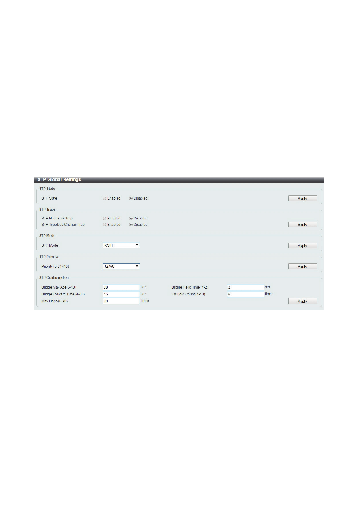
After enabling STP, configure the STP Global Settings (shown below).
Figure 4.76 – L2 Features > STP > STP Global Settings
STP State:
STP State: Select to enable or disable the Spanning Tree Protocol.
Click the Apply button to save your settings.
STP Traps:
STP New Root Trap: Select to enable or disable the STP new root trap option.
STP Topology Change Trap: Select to enable or disable the STP topology change trap option.
Click the Apply button to save your settings.
STP Mode:
STP Mode: Select the STP mode. The options to choose from are MSTP, RSTP and STP.
Click the Apply button to save your settings.
STP Priority:
Loading ...
Loading ...
Loading ...