User Manual
DXS-1210 Series
L2 10 Gigabit Ethernet Switch Series
Rev.A2


D-Link DXS-1210 Series User Manual
i
i
Table of Contents
Table of Contents ............................................................................................................................................. i
About This Guide ............................................................................................................................................. 1
Terms/Usage .................................................................................................................................................. 1
Copyright and Trademarks ............................................................................................................................ 1
1 Product Introduction ................................................................................................................................... 2
DXS-1210-10TS ............................................................................................................................................. 3
Front Panel ................................................................................................................................................. 3
Rear Panel .................................................................................................................................................. 3
DXS-1210-12TC ............................................................................................................................................. 3
Front Panel ................................................................................................................................................. 3
Rear Panel .................................................................................................................................................. 4
DXS-1210-12SC ............................................................................................................................................ 4
Front Panel ................................................................................................................................................. 4
Rear Panel .................................................................................................................................................. 5
DXS-1210-16TC ............................................................................................................................................. 5
Front Panel ................................................................................................................................................. 5
Rear Panel .................................................................................................................................................. 5
2 Hardware Installation .................................................................................................................................. 6
Safety Cautions .............................................................................................................................................. 6
Step 1: Unpacking .......................................................................................................................................... 7
Step 2: Switch Installation .............................................................................................................................. 7
Desktop or Shelf Installation ....................................................................................................................... 7
Rack Installation ......................................................................................................................................... 8
Step 3 – Plugging in the AC Power Cord ....................................................................................................... 8
Power Failure ............................................................................................................................................. 8
3 Getting Started ............................................................................................................................................. 9
Management Options ..................................................................................................................................... 9
Using Web-based Management .................................................................................................................... 9
Supported Web Browsers .......................................................................................................................... 9
Connecting to the Switch ............................................................................................................................ 9
Login Web-based Management ................................................................................................................. 9
Smart Wizard ............................................................................................................................................... 10
Web-based Management ............................................................................................................................. 10
4 Configuration ............................................................................................................................................. 11
Smart Wizard Configuration ......................................................................................................................... 11
IPv4 Information ....................................................................................................................................... 11
SNMP Settings ......................................................................................................................................... 11
User Accounts Settings ............................................................................................................................ 12
Web-based Management ......................................................................................................................... 13
Tool Bar > Save Menu ................................................................................................................................. 13
Save Configuration ................................................................................................................................... 13
Tool Bar > Tool Menu .................................................................................................................................. 14
Firmware Information................................................................................................................................ 14
Configuration Information ......................................................................................................................... 14
Firmware Upgrade & Backup > Firmware Upgrade from HTTP .............................................................. 15
Firmware Upgrade & Backup > Firmware Upgrade from TFTP ............................................................... 15
Firmware Backup to HTTP & Backup > Firmware Backup to HTTP ........................................................ 15

D-Link DXS-1210 Series User Manual
ii
Firmware Backup to HTTP & Backup > Firmware Backup to TFTP ........................................................ 15
Configuration Upgrade & Backup > Configuration Restore from HTTP ................................................... 15
Configuration Upgrade & Backup > Configuration Restore from TFTP ................................................... 16
Configuration Upgrade & Backup > Configuration Backup to HTTP ....................................................... 16
Configuration Upgrade & Backup > Configuration Backup to TFTP ........................................................ 16
Log Backup > Log Backup to HTTP ......................................................................................................... 16
Log Backup > Log Backup to TFTP ......................................................................................................... 17
Ping .......................................................................................................................................................... 17
Reset ........................................................................................................................................................ 17
Reboot System ......................................................................................................................................... 17
Tool Bar > Smart Wizard .............................................................................................................................. 18
Tool Bar > Online Help ................................................................................................................................. 18
Function Tree ............................................................................................................................................... 20
Device Information.................................................................................................................................... 20
System > System Information .................................................................................................................. 20
System > Peripheral ................................................................................................................................. 21
System > Port Configuration > Port Settings ........................................................................................... 21
System > Port Configuration > Port Status .............................................................................................. 22
System > Port Configuration > Error Disable Settings ............................................................................. 23
System > Port Configuration > Jumbo Frame .......................................................................................... 24
System > System Log > System Log Settings ......................................................................................... 24
System > System Log > System Log Server Settings ............................................................................. 25
System > System Log > System Log ....................................................................................................... 25
System > Time and SNTP > Clock Settings ............................................................................................ 25
System > Time and SNTP > Time Zone Settings .................................................................................... 26
System > Time and SNTP > SNTP Settings ............................................................................................ 27
System > Time Range .............................................................................................................................. 27
Management > User Accounts Settings ................................................................................................... 28
Management > Password Encryption ...................................................................................................... 29
Management > SNMP > SNMP Global Settings ...................................................................................... 29
Management > SNMP > SNMP View Table Settings .............................................................................. 30
Management > SNMP > SNMP Community Table Settings .................................................................... 30
Management > SNMP > SNMP Group Table Settings ............................................................................ 31
Management > SNMP > SNMP Engine ID Local Settings ....................................................................... 32
Management > SNMP > SNMP User Table Settings ............................................................................... 32
Management > SNMP > SNMP Host Table Settings ............................................................................... 33
Management > RMON > RMON Global Settings ..................................................................................... 34
Management > RMON > RMON Statistics Settings ................................................................................. 34
Management > RMON > RMON History Settings .................................................................................... 34
Management > RMON > RMON Alarm Settings ...................................................................................... 35
Management > RMON > RMON Event Settings ...................................................................................... 35
Management > Telnet/Web ...................................................................................................................... 36
Management > Session Timeout ............................................................................................................. 37
Management > D-Link Discover Protocol Settings................................................................................... 37
L2 Features > FDB > Static FDB > Unicast Static FDB ........................................................................... 38
L2 Features > FDB > Static FDB > Multicast Static FDB ......................................................................... 38
L2 Features > FDB > MAC Address Table Settings ................................................................................ 38
L2 Features > FDB > MAC Address Table .............................................................................................. 39
L2 Features > 802.1Q VLAN .................................................................................................................... 40

D-Link DXS-1210 Series User Manual
iii
L2 Features > Asymmetric VLAN ............................................................................................................. 40
L2 Features > VLAN Interface .................................................................................................................. 40
L2 Features > Auto Surveillance VLAN > Auto Surveillance Properties .................................................. 42
L2 Features > Auto Surveillance VLAN > MAC Settings and Surveillance Device ................................. 43
L2 Features > Voice VLAN > Voice VLAN Global .................................................................................... 43
L2 Features > Voice VLAN > Voice VLAN Port ....................................................................................... 44
L2 Features > Voice VLAN > Voice VLAN OUI ........................................................................................ 44
L2 Features > Voice VLAN > Voice VLAN Device ................................................................................... 45
L2 Features > Voice VLAN > Voice VLAN LLDP-MED Device ................................................................ 45
L2 Features > STP > STP Global Settings .............................................................................................. 45
L2 Features > STP > STP Port Settings .................................................................................................. 47
L2 Features > STP > MST Configuration Identification............................................................................ 49
L2 Features > STP > STP Instance ......................................................................................................... 49
L2 Features > STP > MSTP Port Information .......................................................................................... 50
L2 Features > ERPS(G.8032) > ERPS .................................................................................................... 50
L2 Features > ERPS(G.8032) > ERPS Profile ......................................................................................... 52
L2 Features > Loopback Detection .......................................................................................................... 53
L2 Features > Link Aggregation ............................................................................................................... 54
L2 Features > L2 Multicast Control > IGMP Snooping > IGMP Snooping Settings ................................. 55
L2 Features > L2 Multicast Control > IGMP Snooping > IGMP Snooping Groups Settings .................... 57
L2 Features > L2 Multicast Control > IGMP Snooping > IGMP Snooping Mrouter Settings ................... 57
L2 Features > L2 Multicast Control > IGMP Snooping > IGMP Snooping Statistics Settings ................. 58
L2 Features > L2 Multicast Control > MLD Snooping > MLD Snooping Setting ...................................... 59
L2 Features > L2 Multicast Control > MLD Snooping > MLD Snooping Groups Setting ......................... 61
L2 Features > L2 Multicast Control > MLD Snooping > MLD Snooping Mrouter Settings ...................... 61
L2 Features > L2 Multicast Control > MLD Snooping > MLD Snooping Statistics Settings .................... 62
L2 Features > L2 Multicast Control > Multicast Filtering .......................................................................... 62
L2 Features > LLDP > LLDP Global Settings .......................................................................................... 63
L2 Features > LLDP > LLDP Port Settings .............................................................................................. 64
L2 Features > LLDP > LLDP Management Address List ......................................................................... 64
L2 Features > LLDP > LLDP Basic TLVs Settings ................................................................................... 65
L2 Features > LLDP > LLDP Dot1 TLVs Settings .................................................................................... 65
L2 Features > LLDP > LLDP Dot3 TLVs Settings .................................................................................... 66
L2 Features > LLDP > LLDP-MED Port Settings ..................................................................................... 67
L2 Features > LLDP > LLDP Statistics Information ................................................................................. 67
L2 Features > LLDP > LLDP Local Port Information ................................................................................ 68
L2 Features > LLDP > LLDP Neighbor Port Information.......................................................................... 69
L3 Features > ARP > ARP Aging Time .................................................................................................... 70
L3 Features > ARP > Static ARP ............................................................................................................. 70
L3 Features > ARP > ARP Table ............................................................................................................. 70
L3 Features > IPv4 Interface .................................................................................................................... 71
L3 Features > IPv4 Static/Default Route .................................................................................................. 72
L3 Features > IPv4 Route Table .............................................................................................................. 73
L3 Features > IPv6 Interface .................................................................................................................... 73
L3 Features > IPv6 Neighbor ................................................................................................................... 74
L3 Features > IPv6 Static/Default Route .................................................................................................. 75
L3 Features > IPv6 Route Table .............................................................................................................. 75
QoS > Port Default CoS ........................................................................................................................... 76
QoS > Port Scheduler Method ................................................................................................................. 77

D-Link DXS-1210 Series User Manual
iv
QoS > Queue Settings ............................................................................................................................. 77
QoS > CoS to Queue Mapping ................................................................................................................ 78
QoS > Port Rate Limiting .......................................................................................................................... 78
QoS > Queue Rate Limiting ..................................................................................................................... 79
QoS > Port Trust State ............................................................................................................................. 79
QoS > DSCP CoS Mapping ..................................................................................................................... 80
ACL > ACL Configuration Wizard ............................................................................................................. 81
ACL > ACL Access List .......................................................................................................................... 103
ACL > ACL Interface Access Group ....................................................................................................... 104
Security > Port Security > Port Security Global Settings ....................................................................... 105
Security > Port Security > Port Security Port Settings ........................................................................... 105
Security > Port Security > Port Security Address Entries ...................................................................... 106
Security > 802.1X > 802.1X Global Settings .......................................................................................... 106
Security > 802.1X > 802.1X Port Settings .............................................................................................. 107
Security > 802.1X > Authentication Sessions Information ..................................................................... 108
Security > 802.1X > Authenticator Statistics .......................................................................................... 108
Security > 802.1X > Authenticator Session Statistics ............................................................................ 108
Security > 802.1X > Authenticator Diagnostics ...................................................................................... 109
Security > AAA > AAA Global Settings .................................................................................................. 109
Security > AAA > Authentication Settings .............................................................................................. 109
Security > RADIUS > RADIUS Global Settings ..................................................................................... 109
Security > RADIUS > RADIUS Server Settings ..................................................................................... 110
Security > RADIUS > RADIUS Group Server Settings .......................................................................... 110
Security > RADIUS > RADIUS Statistic ................................................................................................. 111
Security > Network Access Authentication > Guest VLAN .................................................................... 111
Security > Network Access Authentication > Network Access Authentication Global Settings ............. 111
Security > Network Access Authentication > Network Access Authentication Port Settings ................. 112
Security > Network Access Authentication > Network Access Authentication Sessions Information .... 113
Security > DHCP Server Screening > DHCP Server Screening Global Settings .................................. 114
Security > DHCP Server Screening > DHCP Server Screening Port Settings ...................................... 114
Security > Safeguard Engine.................................................................................................................. 115
Security > Trusted Host .......................................................................................................................... 115
Security > Traffic Segmentation Settings ............................................................................................... 116
Security > Storm Control Settings .......................................................................................................... 116
Security > DoS Attack Prevention Settings ............................................................................................ 117
Security > SSL > SSL Global Setting ..................................................................................................... 118
Security > SSL > SSL Service Policy ..................................................................................................... 118
OAM > Cable Diagnostics ...................................................................................................................... 119
Monitoring > Statistics > Port ................................................................................................................. 120
Monitoring > Statistics > Port Counters .................................................................................................. 121
Monitoring > Statistics > Counters ......................................................................................................... 121
Monitoring > Mirror Settings ................................................................................................................... 122
Green > Power Saving ........................................................................................................................... 123
Green > EEE .......................................................................................................................................... 124
Appendix A - Technical Specifications ..................................................................................................... 125
Hardware Specifications ............................................................................................................................ 125
Key Components / Performance ............................................................................................................ 125
Port Functions ........................................................................................................................................ 125
Physical & Environment ......................................................................................................................... 125

D-Link DXS-1210 Series User Manual
v
Emission (EMI) Certifications ................................................................................................................. 125
Safety Certifications................................................................................................................................ 126
Features ..................................................................................................................................................... 126
L2 Features ............................................................................................................................................ 126
L3 Features ............................................................................................................................................ 126
D-Link Green Technology ...................................................................................................................... 126
VLAN ...................................................................................................................................................... 126
QoS (Quality of Service) ......................................................................................................................... 126
Security ................................................................................................................................................... 127
Management ........................................................................................................................................... 127

D-Link DXS-1210 Series User Manual
1
About This Guide
This guide provides installation and instructions for the D-Link 10 Gigabit Ethernet L2 Switch (DXS-1210-
12TC/12SC/10TS/16TC),
Note: T
he model you have purchased may
appear slightly different from the illustrations
shown in the document. Refer to the sections for
detailed information about your switc
h, its
components, network connections, and technical
specifications.
This guide is divided into four parts:
1. Hardware Installation: Step-by-step hardware installation procedures.
2. Getting Started: A startup guide for basic switch installation and settings.
3. D-Link Network Assistant: An introduction to the central configuration utility.
4. Configuration: Information about the function descriptions and configuration settings.
Terms/Usage
In this guide, the term “Switch” (first letter capitalized) refers to the DSX-1210 Series switch and “switch” (first
letter lower case) refers to other Ethernet switches. Some technologies use “switch”, “bridge” and “switching
hubs” interchangeably, and all are commonly accepted terms for Ethernet switches.
A NOTE indicates important
information that
helps you make better use of the device.
A CAUTION indicates the potential for property
damage or personal injury.
Copyright and Trademarks
Information in this document is subjected to change without notice.
© 2016 D-Link Corporation. All rights reserved.
Reproduction in any manner whatever without the written permission of D-Link Corporation is strictly
forbidden.
Trademarks used in this text: D-Link and the D-LINK logo are trademarks of D-Link Corporation; Microsoft
and Windows are registered trademarks of Microsoft Corporation.
Other trademarks and trade names may be used in this document to refer to either the entities claiming the
marks and names or their products. D-Link Corporation disclaims any proprietary interest in trademarks and
trade names other than its own.

D-Link DXS-1210 Series User Manual
2
1 Product Introduction
Thank you and congratulations on your purchase of D-Link DXS-1210 Series Switch.
D-Link's latest generation L2 10 Gigabit Ethernet switch series blends plug-and-play simplicity with
exceptional value and reliability for small and medium-sized business (SMB) networking. All models are
housed in a new style rack-mount metal case with easy-to-view front panel diagnostic LEDs, and provide
advance features including network security, traffic segmentation, QoS and versatile management.
Flexible Port Configurations: The DXS-1210 Series is D-Link’s latest 10G switch which provides 8-port,
10-port 10GBASE-T and 12-port SFP+ models. The DXS-1210 Series switches, have the advantage of using
intuitive feature-rich software and utilizing a neat and simplified Web GUI allowing users to access and
configure the Switch from everywhere via a web browser. 10GBASE-T provides the requisite backward
compatibility that allows end users to transparently upgrade from 10/100/1000Mbps to 10 Gbps, using Cat 6,
6A, 7 unshielded and shielded twisted-pair cables. 10G SFP+ has the advantage of lower power
consumption, longer cable distance, and better latency performance. Direct Attach Cables (DACs) can be
used to provide a cost effective way of connecting switches at 10 Gbps that are in close proximity to each
other.
D-Link Green Technology: D-Link Green devices aim to provide eco-friendly alternatives without
compromising performance. D-Link Green Technology includes a number of innovations to reduce energy
consumption on DXS-1210 series switches, such as reducing power when a port does not have a device
attached, or adjusting the power usage according to the length of Ethernet cable connected to it.
Extensive Layer 2 Features: Implemented as complete L2 devices, these switches include functions such
as IGMP snooping, port mirroring, Spanning Tree, ERPS, 802.3ad LACP, SNTP, LLDP and Loopback
Detection to enhance performance and network reliability.
Extensive Layer 3 Features: These switches include functions such as IP interfaces, static routes, IPv6
static routes, and ARP to enhance performance and network resiliency.
QoS: The switches support bandwidth control and 802.1p priority queues, enabling users to run bandwidth-
sensitive applications such as voice and video on the network. These functions allow the switches to work
seamlessly with VLANs, 802.1p traffic and IPv6 Traffic Class priority to prioritize traffic on the network.
Network Security: D-Link’s innovative Safeguard Engine function protects the switches against traffic
flooding caused by virus attacks. Additional features such as Storm Control can help to keep the network
from being overwhelmed by abnormal traffic. Port Security is another simple but useful authentication
method to maintain the network device integrity. Also supports DHCP Server Screening, SSL and IP-MAC-
Port Binding features.
Versatile Management: The new generation of D-Link 10 Gigabit Ethernet Switches provide growing
businesses with a simple and easy management of their network, using a web-based management interface
that allows administrators to remotely control their network down to the port level. Adding a console port with
RJ-45 for command line interface management. The Switch can be managed, out-of-band, by using the
console port on the front panel of the Switch. Alternatively, the Switch can also be managed, in-band, by
using a Telnet connection to any of the LAN ports on the Switch. And the command line interface provides
complete access to all switch management features.
Users can also access the switch via Telnet. Some basic tasks can be performed such as changing the
Switch IP address, resetting the settings to factory defaults, setting the administrator password, rebooting the
Switch, or upgrading the Switch firmware by using the Command Line Interface (CLI).
In addition, users can utilize the SNMP MIB (Management Information Base) to poll the switches for
information about the status, or send out traps of abnormal events. SNMP support allows users to integrate
the switches with other third-party devices for management in an SNMP-enabled environment. D-Link Smart
Managed Switches provides easy-to-use graphic interface and facilitates the operation efficiency.
D-Link DXS-1210 Series User Manual
3
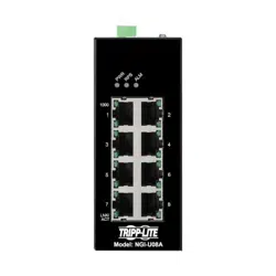
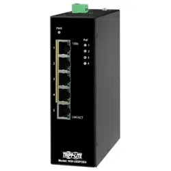
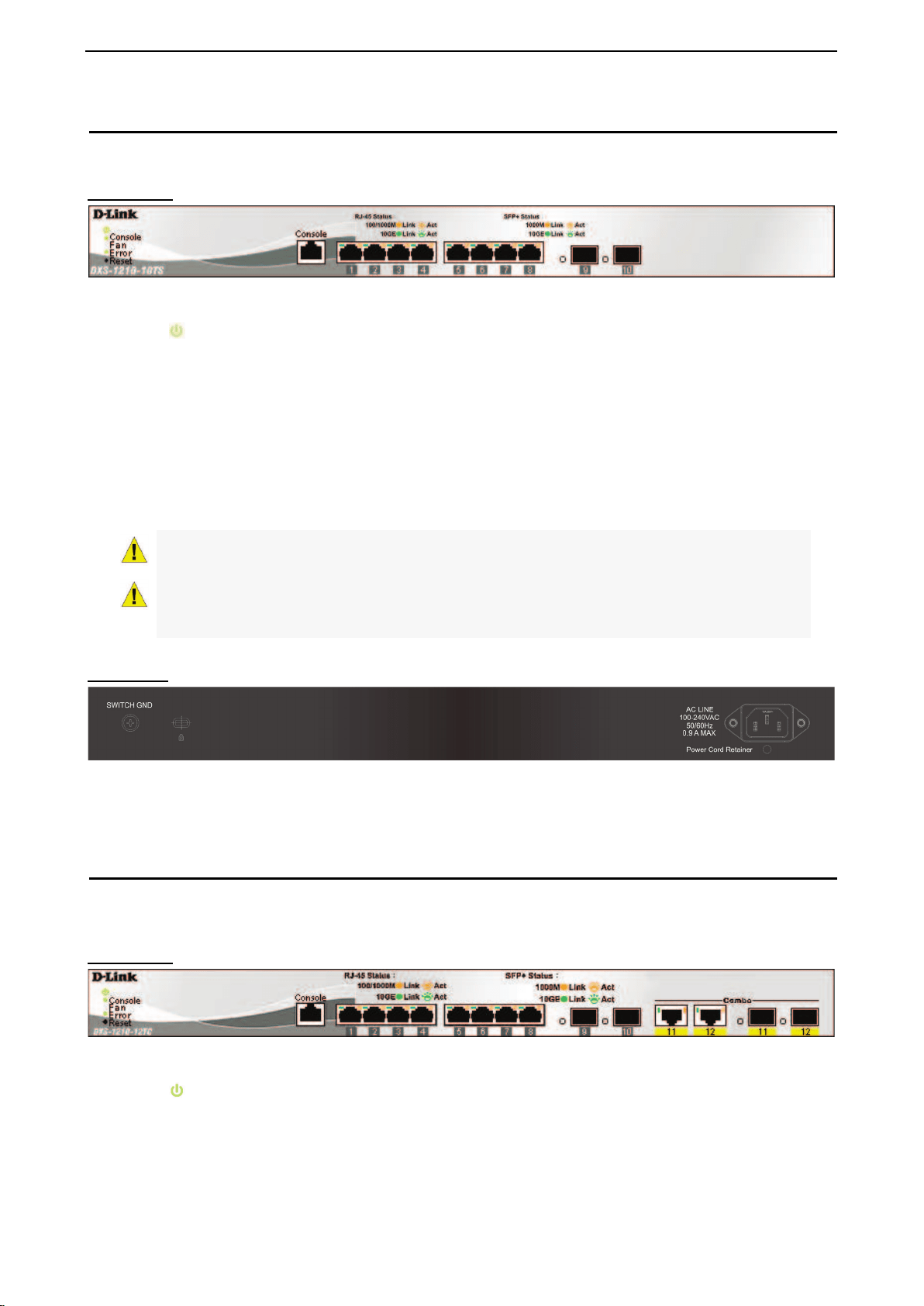
DXS-1210-10TS
8-Port 10GBASE-T and 2-Port SFP + Fiber port L2 10 Gigabit Ethernet Switch.
Front Panel
Figure 1.1 – DXS-1210-10TS Front Panel
Power LED
: The Power LED lights up when the Switch is connected to a power source.
Console: The console LED lights up when the console port is connected.
Fan error: The Fan error LED lights up when the fan has runtime failure and is brought offline.
Reset: By pressing the Reset button, the Switch will change back to the default configuration and all
changes will be lost.
Port Link/Act/Speed LED (1-8, 9F, 10F): The port LEDs indicate a network link through the corresponding
port. Blinking indicates the Switch is either sending or receiving data to the port. When the port LED glows
amber, it indicates the port is running at 100 mbps or 1000 Mbps. When the port LED glows green, it is
running at 10 Gbps.
CAUTION: The MiniGBIC ports should use UL
listed Optical Transceiver product, Rated
Laser Class I. 3.3Vdc
PRUDENCE: Si le transceiveur optique n'est paslivr avec l'appareil, le manuel d'utilisation
doitcomporter la description ci-dessous ou sonquivalent : Ce produit est destin tre utilisavec
un transceiveur optique homologuUL,tension DC3.3V, classe laser I.
Rear Panel
Figure 1.2 – DXS-1210-10TS Rear Panel
Power: Connect the AC power cord to this port.
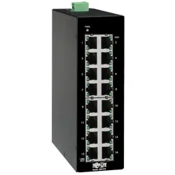
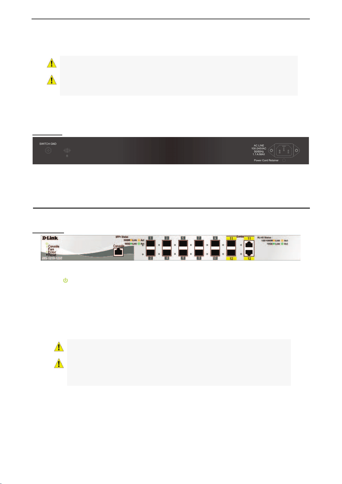
DXS-1210-12TC
8-port 10GBASE-T and 2-port 10G SFP+ with additional 2-port 10GBASE-T/SFP+ combo port L2 10 Gigabit
Ethernet Switch.
Front Panel
Figure 1.3 – DXS-1210-12TC Front Panel
Power LED : The Power LED lights up when the Switch is connected to a power source.
Console: The console LED lights up when the console port is connected.
Fan error: The Fan error LED lights up when the fan has runtime failure and is brought offline.
Port Link/Act/Speed LED (1-8, 9F, 10F, 11F, 12F): The Link/Act/Speed LED flashes, which indicates a
network link through the corresponding port. Blinking indicates that the Switch is either sending or receiving
D-Link DXS-1210 Series User Manual
4
data to the port. When a port has an amber light, this indicates that the port is running at 100 Mbps or 1000
Mbps. When it has a green light it is running on 10 Gbps.
CAUTION: The MiniGBIC ports should use UL listed Optical Transceiver product, Rated
Laser Class I. 3.3Vdc.
PRUDENCE: Si le transceiveur optique n'est paslivr avec l'appareil, le manuel d'utilisation
doitcomporter la description ci-
dessous ou sonquivalent : Ce produit est destin tre
utilisavec un transceiveur optique homologuUL,tension DC3.3V, classe laser I.
Reset: By pressing the Reset button, the Switch will change back to the default configuration and all
changes will be lost.
Rear Panel
Figure 1.4 – DXS-1210-12TC Rear Panel
Power: Connect the AC power cord to this port.
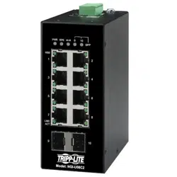
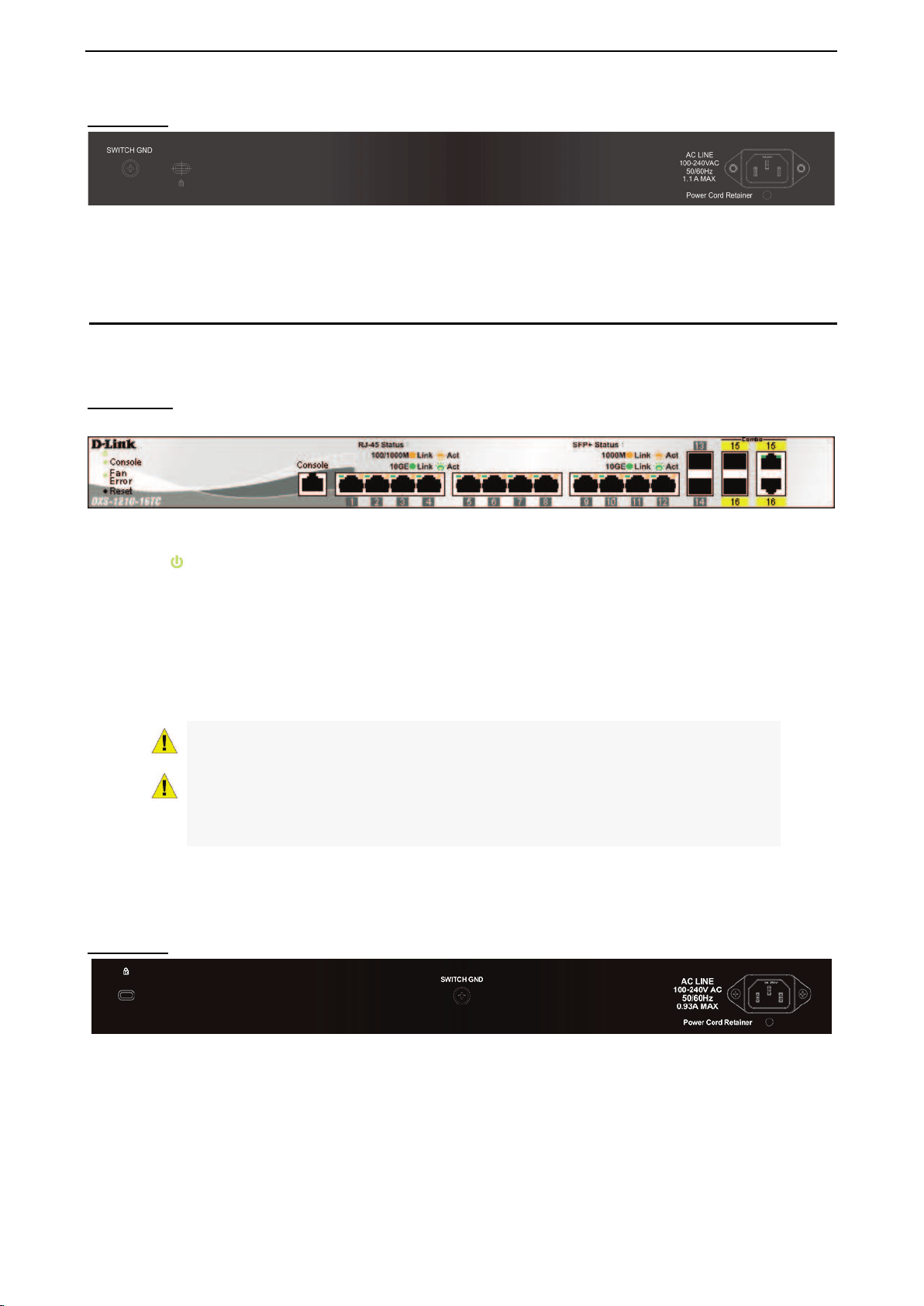
DXS-1210-12SC
10-Port 10G SFP+ fiber port and 2-port 10GBASE-T/SFP + combo port L2 10 Gigabit Ethernet Switch.
Front Panel
Figure 1.5 – DXS-1210-12SC Front Panel
Power LED : The Power LED lights up when the Switch is connected to a power source.
Console: The console LED lights up when the console port is connected.
Fan error: The Fan error LED lights up when the fan has runtime failure and is brought offline.
Port Link/Act/Speed LED (1-10, 11F, 12F): The Link/Act/Speed LED flashes, which indicates a network link
through the corresponding port. Blinking indicates that the Switch is either sending or receiving data to the
port. When a port has an amber light, this indicates that the port is running on 100 Mbps or 1000 Mbps.
When it has a green light it is running on 10 Gbps.
CAUTION:
The MiniGBIC ports should use UL listed Optical Transceiver product,
Rated Laser Class I. 3.3Vdc.
PRUDENCE:
Si le transceiveur optique n'est paslivr avec l'appareil, le manuel
d'utilisation doitcomporter la description ci-dessous ou sonquivalent : Ce produit est
destin tre utilisavec un transceiveur optique homologuUL,tension DC3.3V, classe
laser I.
Reset: By pressing the Reset button, the Switch will change back to the default configuration and all
changes will be lost.
D-Link DXS-1210 Series User Manual
5
Rear Panel
Figure 1.6 – DXS-1210-12SC Rear Panel
Power: Connect the AC power cord to this port.
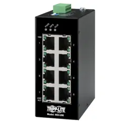
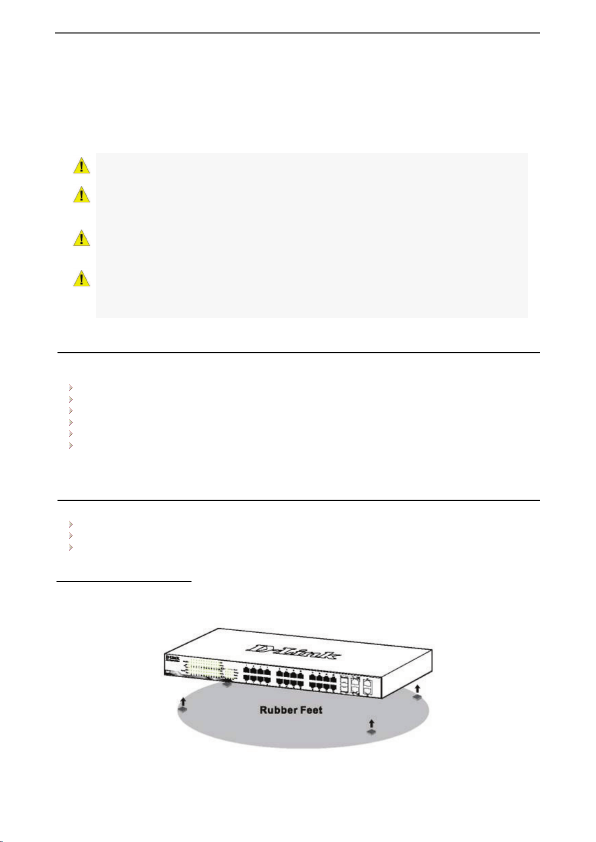
DXS-1210-16TC
12-Port 10G SFP+ fiber port, 2-port 10GBASE-T/SFP+ and 2-port 10BGASE-T/SFP+ combo port L2 10
Gigabit Ethernet Switch.
Front Panel
Figure 1.7 – DXS-1210-16TC Front Panel
Power LED
: The Power LED lights up when the Switch is connected to a power source.
Console: The console LED lights up when the console port is connected.
Fan error: The Fan error LED lights up when the fan has runtime failure and is brought offline.
Port Link/Act/Speed LED (1-12, 13F, 14F, 15T, 15F, 16T, 16F): The Link/Act/Speed LED flashes, which
indicates a network link through the corresponding port. Blinking indicates that the Switch is either sending or
receiving data to the port. When a port has an amber light, this indicates that the port is running on 100 Mbps
or 1000 Mbps. When it has a green light it is running on 10 Gbps.
CAUTION: The MiniGBIC ports should use UL listed Optical Transceiver product,
Rated Laser Class I. 3.3Vdc.
PRUDENCE:
Si le transceiveur optique n'est paslivr avec l'appareil, le manuel
d'utilisation doitcomporter la description ci-dessous ou sonquivalent : Ce produit est
destin tre utilisavec un transceiveur optique homologuUL,tension DC3.3V, classe
laser I.
Reset: By pressing the Reset button for 1 ~ 5 seconds to reboot the device. By pressing the Reset button for
6 ~ 10 seconds, the Switch will change back to the default configuration and all changes will be lost.
Rear Panel
Figure 1.8 – DXS-1210-16TC Rear Panel
Power: Connect the AC power cord to this port.

D-Link DXS-1210 Series User Manual
6
2 Hardware Installation
This chapter provides unpacking and installation information for the D-Link DXS-1210 Series Switch.
Safety Cautions
To reduce the risk of bodily injury, electrical shock, fire and damage to the equipment, observe the following
precautions:
• Observe and follow service markings.
• Do not service any product except as explained in your system documentation.
• Opening or removing covers that are marked with the triangular symbol with a lightning bolt may
expose you to electrical shock.
• Only a trained service technician should service components inside these compartments.
• If any of the following conditions occur, unplug the product from the electrical outlet and replace the part
or contact your trained service provider:
• The power cable, extension cable, or plug is damaged.
• An object has fallen into the product.
• The product has been exposed to water.
• The product has been dropped or damaged.
• The product does not operate correctly when you follow the operating instructions.
• Keep your system away from radiators and heat sources. Also, do not block cooling vents.
• Do not spill food or liquids on your system components, and never operate the product in a wet
environment. If the system gets wet, contact your trained service provider.
• Do not push any objects into the openings of your system. Doing so can cause fire or electric shock by
shorting out interior components.
• Use the product only with approved equipment.
• Allow the product to cool before removing covers or touching internal components.
• Operate the product only from the type of external power source indicated on the electrical ratings label.
If you are not sure of the type of power source required, consult your service provider or local reseller.
• Also, be sure that attached devices are electrically rated to operate with the power available in your
location.
• Use only approved power cable(s). If you have not been provided with a power cable for your system or
for any AC powered option intended for your system, purchase a power cable that is approved for use in
your country. The power cable must be rated for the product and for the voltage and current marked on
the product’s electrical ratings label. The voltage and current rating of the cable should be greater than
the ratings marked on the product.
• To help prevent electric shock, plug the system and peripheral power cables into properly grounded
electrical outlets.
• These cables are equipped with three-prong plugs to help ensure proper grounding. Do not
use adapter plugs or remove the grounding prong from a cable. If you must use an extension
cable, use a 3-wire cable with properly grounded plugs.
• Observe extension cable and power strip ratings. Make sure that the total ampere rating of all
products plugged into the extension cable or power strip does not exceed 80 percent of the
ampere ratings limit for the extension cable or power strip.
• To help protect your system from sudden, transient increases and decreases in electrical
power, use a surge suppressor, line conditioner, or uninterruptible power supply (UPS).
• Position system cables and power cables carefully; route cables so that they cannot be
stepped on or tripped over. Be sure that nothing rests on any cables.
• Do not modify power cables or plugs. Consult a licensed electrician or your power company for
site modifications.
• Always follow your local/national wiring rules.
• When connecting or disconnecting power to hot-pluggable power supplies, if offered with your
system, observe the following guidelines:
D-Link DXS-1210 Series User Manual
7
• Install the power supply before connecting the power cable to the power supply.
• Unplug the power cable before removing the power supply.
• If the system has multiple sources of power, disconnect power from the system by
unplugging all power cables from the power supplies.
• Move products with care; ensure that all casters and/or stabilizers are firmly connected to the system.
Avoid sudden stops and uneven surfaces.
Caution: Suitable for installation in Information Technology Rooms in accordance with Article
645 of the National Electrical Code and NFPA 75.
PRUDENCE: Équipement conforme à la clause 62368-1 pour l'installation :
Convient pour une installation dans les salles informatiques conformément à l'article 645 du
National Electrical Code et à la norme NFPA 75.
Caution: The device can only be used in a fixed location such as a lab or a machine room.
When you install the device, ensure that the protective earthing connection of the socket-outlet
is verified by a skilled person.
PRUDENCE: L'appareil ne peut être utilisé que dans un lieu fixe, tel qu'un laboratoire ou une
salle de machines. Lorsque vous installez l'appareil, assurez-vous que le raccordement à la
terre de protection de la prise de courant a fait lobjet dune vérification par une personne
qualifiée.
Step 1: Unpacking
Open the shipping carton and carefully unpack its contents. Please consult the packing list located in the
User Manual to make sure all items are present and undamaged.
One D-Link DXS-1210 Series switch
One Multilingual Getting Started Guide
User Guide CD
One RJ-45 console cable
Power Cord and Power Cord Retainer
Rack-mount kit and Rubber Feet
If any item is found missing or damaged, please contact the local reseller for replacement.
Step 2: Switch Installation
For safe switch installation and operation, it is recommended that you:
Visually inspect the power cord to see that it is secured fully to the AC power connector.
Make sure that there is proper heat dissipation and adequate ventilation around the switch.
Do not place heavy objects on the switch.
Desktop or Shelf Installation
When installing the switch on a desktop or shelf, the rubber feet included with the device must be attached
on the bottom at each corner of the device’s base. Allow enough ventilation space between the device and
the objects around it.
Figure 2.1 – Attach the adhesive rubber pads to the bottom
D-Link DXS-1210 Series User Manual
8
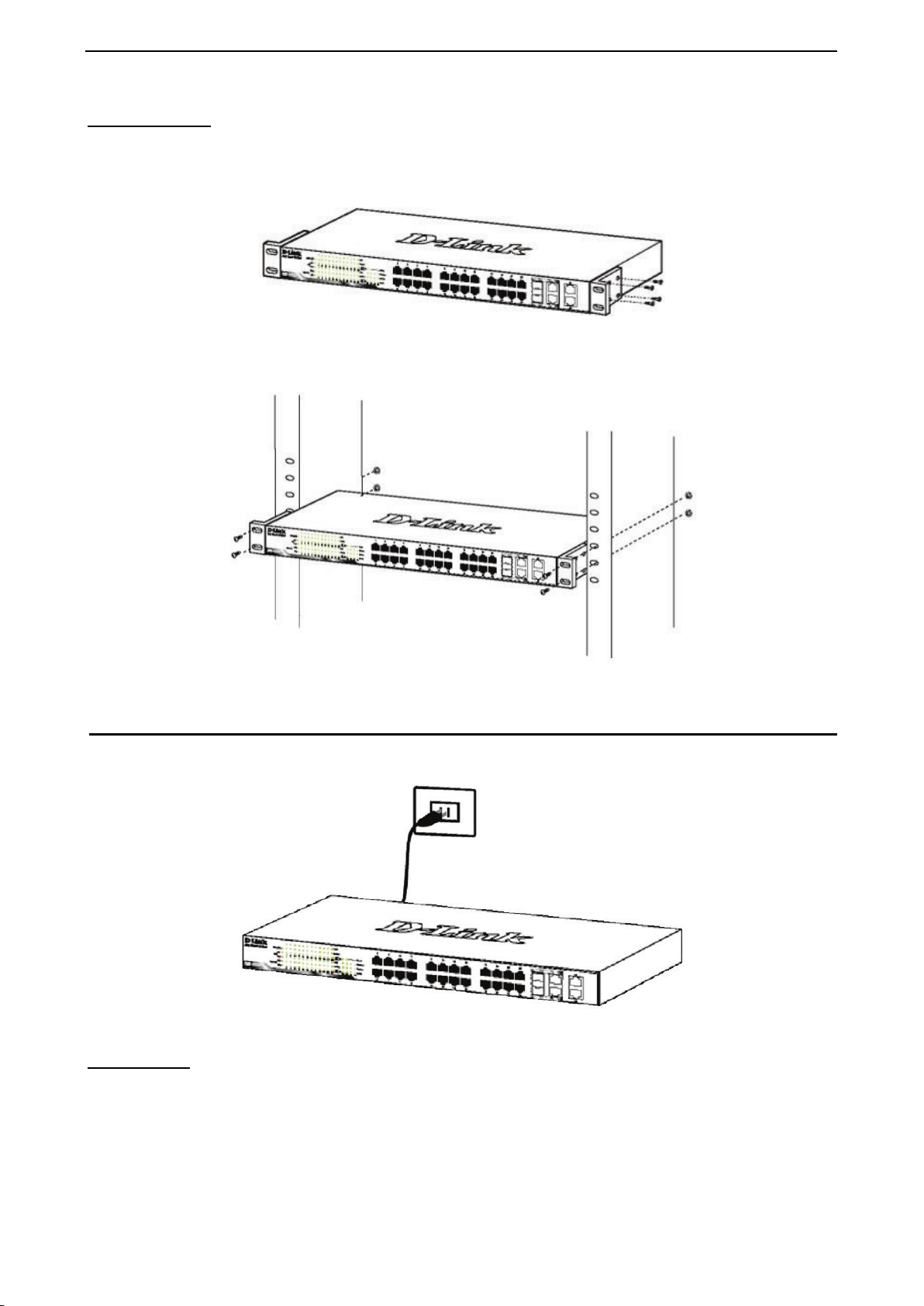
Rack Installation
The switch can be mounted in an EIA standard size 19-inch rack, which can be placed in a wiring closet with
other equipment. To install, attach the mounting brackets to the switch’s side panels (one on each side) and
secure them with the screws provided (with 8 M3*6.0 size screws).
Figure 2.2 – Attach the mounting brackets to the Switch
Then, use the screws provided with the equipment rack to mount the switch in the rack.
Figure 2.3 – Mount the Switch in the rack or chassis
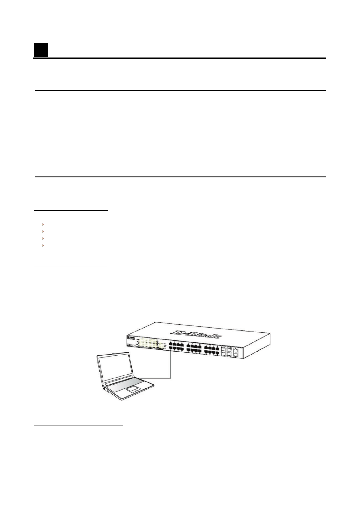
Step 3 – Plugging in the AC Power Cord
The Switch can now be connected to the AC power. Connect the AC power cord to the rear of the switch and
to an electrical outlet (preferably one that is grounded and surge protected).
Figure 2.4 –Plugging the switch into an outlet
Power Failure
As a precaution, the switch should be unplugged in case of power failure. When power is resumed, plug the
switch back in.
D-Link DXS-1210 Series User Manual
9
3 Getting Started
This chapter introduces the management interface of D-Link DXS-1210 Series Switch.
Management Options
The D-Link DXS-1210 Series Switch can be managed through any port by using the Web-based
Management, or through any PC using CLI commands.
Each switch must be assigned its own IP Address, which is used for communication with the Web-Based
Management or a SNMP network manager. The PC should have an IP address in the same subnet as the
switch. Each switch can allow up to four users to access the Web-Based Management concurrently.
Please refer to the following installation instructions for the Web-based Management.
Using Web-based Management
After a successful physical installation, you can configure the Switch, monitor the network status, and display
statistics using a web browser.
Supported Web Browsers
The embedded Web-based Management currently supports the following web browsers:
Internet Explorer 8 or later version
Chrome
Firefox
Safari
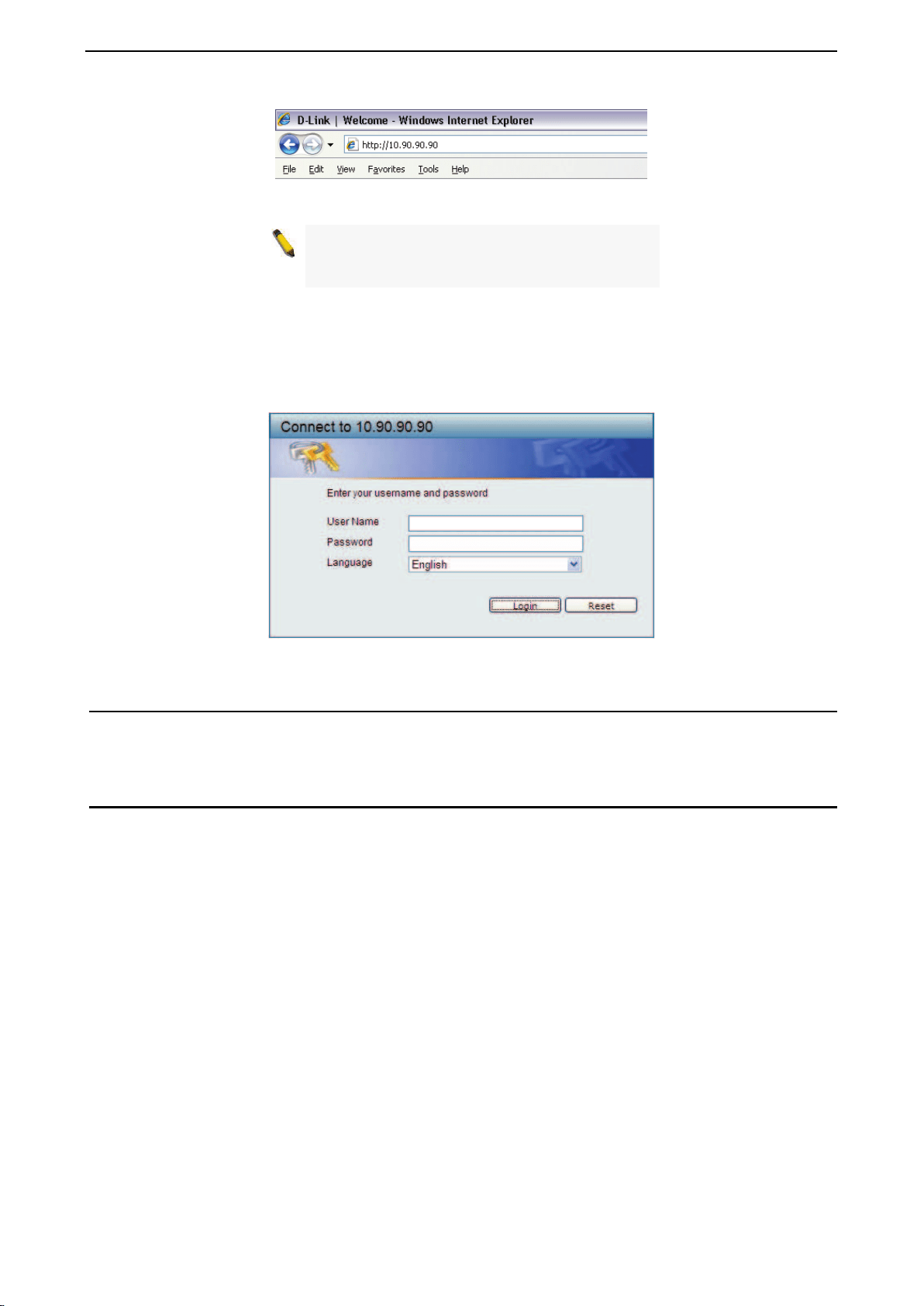
Connecting to the Switch
You will need the following equipment to begin the web configuration of your device:
1. A PC with a RJ-45 Ethernet connection
2. A standard Ethernet cable
Connect the Ethernet cable to any of the ports on the front panel of the switch and to the Ethernet port on the
PC.
Figure 3.1 – Connected Ethernet cable
Login Web-based Management
In order to login and configure the switch via Web-based GUI, the PC must have an IP address in the same
subnet as the switch. For example, if the switch has an IP address of 10.90.90.90, the PC should have an IP
address of 10.x.y.z (where x/y is a number between 0 ~ 254 and z is a number between 1 ~ 254), and a
subnet mask of 255.0.0.0. There are two ways to launch the Web-based Management.
D-Link DXS-1210 Series User Manual
10
Figure 3.2 –Enter the IP address 10.90.90.90 in the web browser
NOTE: The switch's factory default IP address is
10.90.90.90 with a subnet mask of 255.0.0.0 and
a default gateway of 0.0.0.0.
When the following login dialog box appears, enter the password and choose the language of the Web-
based Management interface then click OK.
The switch supports 10 languages including English, Traditional Chinese, Simplified Chinese, German,
Spanish, French, Italian, Portuguese, Japanese and Russian. By default, the Username and Password are
empty and the language is English.
Figure 3.3 – Login Dialog Box
Smart Wizard
After a successful login, the Smart Wizard will guide you through essential settings of the D-Link DXS-1210
Series Switch. Please refer to the Smart Wizard Configuration section for details.
Web-based Management
By clicking the Exit button in the Smart Wizard, you will enter the Web-based Management interface. Please
refer to Chapter 4 Configuration for detailed instructions.
D-Link DXS-1210 Series User Manual
11
4 Configuration
The features and functions of the D-Link DXS-1210 Series Switch can be configured for optimum use
through the Web-based Management Utility.
Smart Wizard Configuration
After a successful login, the Smart Wizard will guide you through essential settings of the D-Link DXS-1210
Series Switch. If you do not plan to change anything, click Exit to leave the Wizard and enter the Web
Interface. You can also skip it by clicking Ignore the wizard next time for the next time you logon to the
Web-based Management.
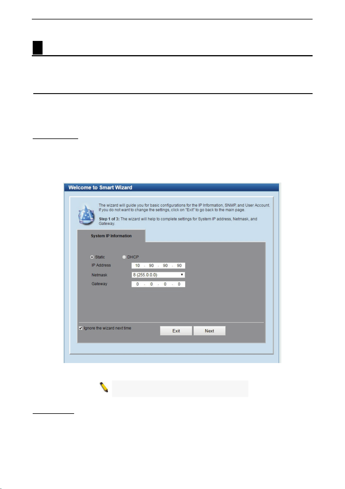
IPv4 Information
IPv4 Information will guide you to do basic configurations on 3 steps for the IP Information, access password,
and SNMP. Select Static, to manually enter a new IP Address, Netmask and Gateway address, or select
DHCP to automatically receive IP settings from a DHCP server. Click the Next button to enter the SNMP
settings page The IP address is allowed for IPv4 and IPv6 address. If you are not changing the settings, click
Exit button to go back to the main page. Or you can click on Ignore the wizard next time to skip wizard
setting when the switch boots up.
Figure 4.1 – IPv4 Information in Smart Wizard
NOTE:
The IPv4 Information of Smart Wizard
does not support IPv6 address.
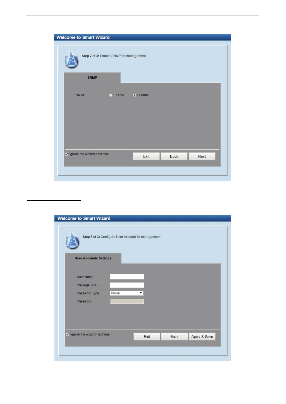
SNMP Settings
The SNMP Settings page allows you to quickly enable/disable the SNMP function. The default SNMP Setting
is Disabled. Click Enabled and then click Next, then it will enter the User Accounts Settings page.
D-Link DXS-1210 Series User Manual
12
Figure 4.2 – SNMP Settings in Smart Wizard
User Accounts Settings
The User Accounts Settings page allows you to quickly specify the user account function. Enter the User
Name, Privilege, Password Type and Password. Click Apply & Save to save the configuration.
Figure 4.3 – User Accounts Setting in Smart Wizard
D-Link DXS-1210 Series User Manual
13
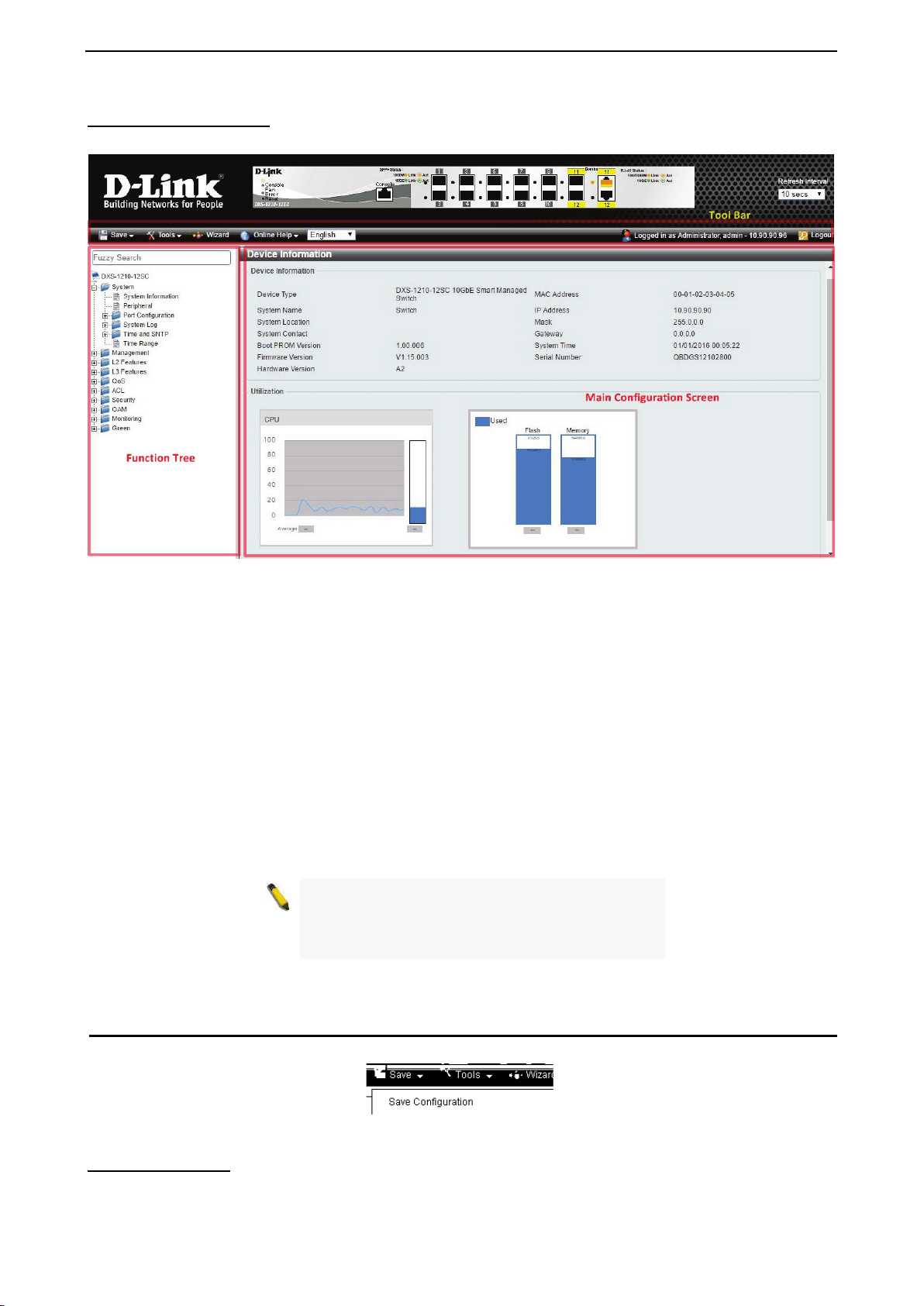
Web-based Management
After clicking the Exit button in the Smart Wizard you will see the screen below:
Figure 4.4 – Web-based Management
The above image is the Web-based Management screen. The three main areas are the Tool Bar on top, the
Function Tree, and the Main Configuration Screen.
The Tool Bar provides a quick and convenient way for essential utility functions like firmware and
configuration management.
By choosing different functions in the Function Tree, you can change all the settings in the Main
Configuration Screen. The main configuration screen will show the current status of your Switch by clicking
the model name on top of the function tree.
At the upper right corner of the screen the username and current IP address will be displayed.
Under the username is the Logout button. Click this to end this session.
NOTE: If you close the web browser without
clicking the Logout button first, then it will be seen
as an abnormal exit and the login session will still
be occupied.
Click the D-Link logo at the upper-left corner of the screen to be redirected to the local D-Link website.
Tool Bar > Save Menu
The Save Menu provides Save Configuration and Save Log functions.
Figure 4.5 – Save Menu
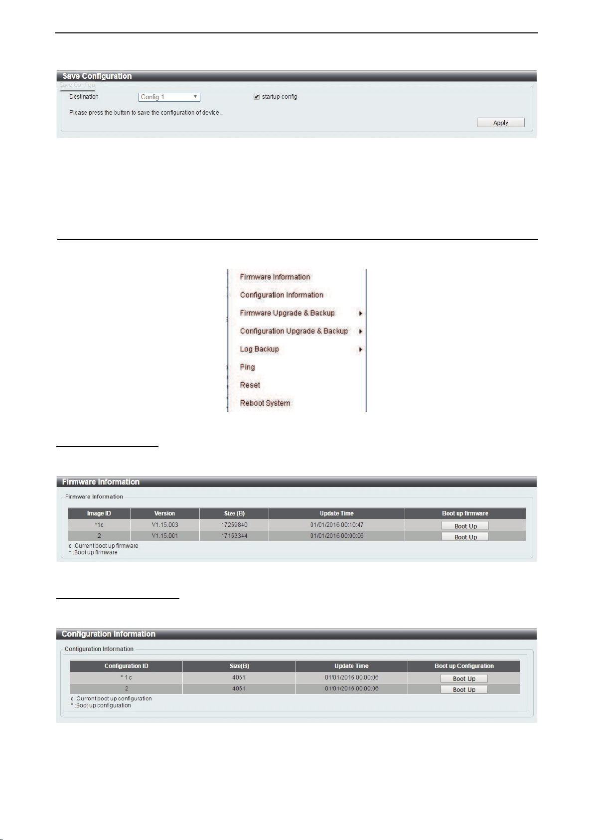
Save Configuration
Select Save configuration to save the configuration changes to the Switch’s non-volatile RAM.
D-Link DXS-1210 Series User Manual
14
Figure 4.6 – Save Configuration
Destination: Select the destination to save the configuration to.
Startup-config: Check the box to enable the startup configuration function.
Click the Apply button to save your settings.
Tool Bar > Tool Menu
The Tool Menu offers global functions controls such as Reset, Reboot Device, Configuration Backup and
Restore, Firmware Backup and Upgrade.
Figure 4.7 – Tool Menu
Firmware Information
Display the firmware for the 2 firmware images, including the image that has been booted and the image that
is selected for the next reboot.
Figure 4.8 – Tool Menu > Firmware Information
Configuration Information
Display information for the Switch configuration. This includes the configuration that has been loaded and the
configuration that is selected for the next reboot.
Figure 4.9 – Tool Menu > Configuration Information
D-Link DXS-1210 Series User Manual
15
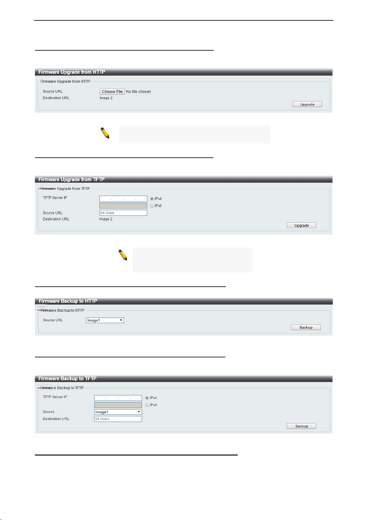
Firmware Upgrade & Backup > Firmware Upgrade from HTTP
To upgrade the firmware of Switch from a firmware file, select a Source URL, firmware Destination URL
and click Upgrade. The specified firmware file will be uploaded to the Switch via HTTP.
Figure 4.10 – Tool Menu > Firmware Upgrade & Backup > Firmware Upgrade from HTTP
Note: The Switch will reboot after restoring the
firmware, and all current configuration will be lost.
Firmware Upgrade & Backup > Firmware Upgrade from TFTP
Upgrade firmware using TFTP. Enter the TFTP IP address, source URL, and select a Destination URL. Click
Upgrade.
Figure 4.11 – Tool Menu > Firmware Upgrade & Backup > Firmware Upgrade from TFTP
Note: The Switch will reboot after
restoring the firmware,
and all current
configuration will be lost.
Firmware Backup to HTTP & Backup > Firmware Backup to HTTP
To save a backup of the firmware, select the source URL and then click Backup.
Figure 4.12 – Tool Menu > Firmware Upgrade & Backup > Firmware Backup to HTTP
Firmware Backup to HTTP & Backup > Firmware Backup to TFTP
To save a backup of the firmware using TFTP, enter the TFTP server IP address, the source URL, and the
destination URL. Click Backup.
Figure 4.13 – Tool Menu > Firmware Upgrade & Backup > Firmware Backup to TFTP
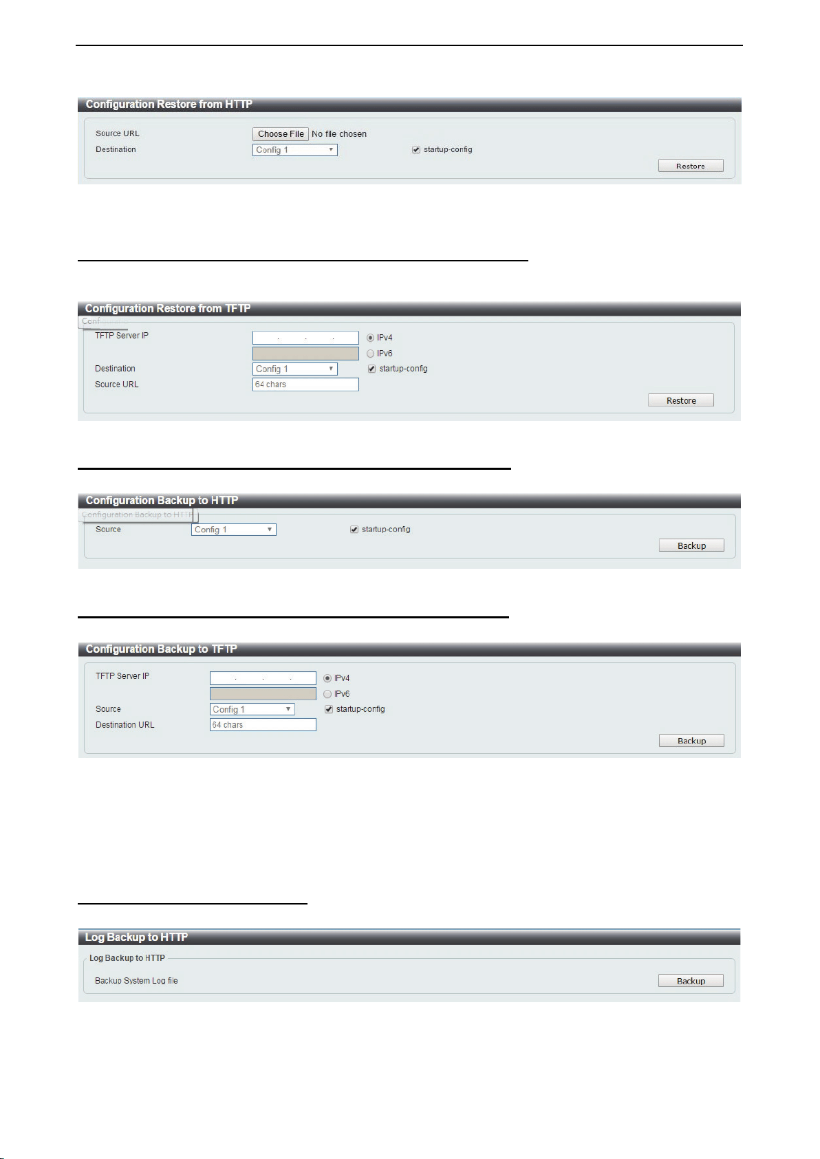
Configuration Upgrade & Backup > Configuration Restore from HTTP
To restore the Switch from a saved configuration file, select a Source URL, configuration Destination and
click Restore.
D-Link DXS-1210 Series User Manual
16
Figure 4.14 – Tool Menu > Configuration Upgrade & Backup > Configuration Restore from HTTP
Startup-config: Check the box to enable the startup configuration function.
Configuration Upgrade & Backup > Configuration Restore from TFTP
To load the Switch’s configuration from a saved configuration file using TFTP, enter the TFTP server IP
address, destination image and source URL, then click Restore.
Figure 4.15 – Tool Menu > Configuration Upgrade & Backup > Configuration Restore from TFTP
Configuration Upgrade & Backup > Configuration Backup to HTTP
To save the current configuration to a file, click Backup.
Figure 4.16 – Tool Menu > Configuration Upgrade & Backup > Configuration Backup to HTTP
Configuration Upgrade & Backup > Configuration Backup to TFTP
To save the current configuration to a file using TFTP, click Backup.
Figure 4.17 – Tool Menu > Configuration Upgrade & Backup > Configuration Backup to TFTP
TFTP Server IP: Select IPv4 or IPv6 and enter the IP address.
Source: Select the source configuration file.
Startup-config: when checking the box, only the current startup configuration file will be backed up, which
may be stored in the “Config 1” or “Config 2” location.
Destination URL: Enter the destination URL for the backup.
Log Backup > Log Backup to HTTP
To save the log to a file and click Backup.
Figure 4.18 – Tool Menu > Log Backup > Log Backup to HTTP
D-Link DXS-1210 Series User Manual
17
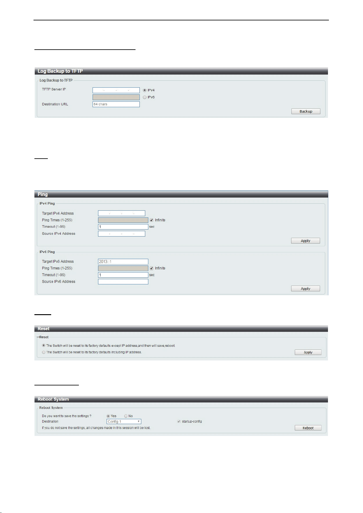
Log Backup > Log Backup to TFTP
To save the log to a file using TFTP, enter the TFTP server IP address and destination URL then click
Backup.
Figure 4.19 – Tool Menu > Log Backup > Log Backup to TFTP
TFTP Server IP: Select IPv4 or IPv6 and enter the IP address.
Destination URL: Enter the destination URL for the backup.
Ping
To ping a computer or device, enter either Target IPv4 Address or Target IPv6 Address, Ping Times,
Timeout and Source IPv4 Address or Source IPv6 Address. Enter the required information, tick the
Infinite option to disable the Ping Times feature, and click Apply. The results will be displayed in the Result
box.
Figure 4.20 – Ping
Reset
Select which reset option you want to perform and click Apply.
Figure 4.21 – Tool Menu > Reset
Reboot System
Select to save your current settings and then click Reboot to restart the Switch.
Figure 4.22 – Tool Menu > Reboot System
Destination: Select the configuration destination to be saved.
Startup-config: When checking the box, only the current startup configuration file will be backed up which
may be stored in the “Config 1” or “Config 2” location.

D-Link DXS-1210 Series User Manual
18
Tool Bar > Smart Wizard
By clicking the Smart Wizard button, you can re-run to the Smart Wizard if you wish to make any changes.
Tool Bar > Online Help
The Online Help provides two ways of online support: D-link Support Site will lead you to the D-Link
website where you can find online resources such as updated firmware; User Guide can offer an immediate
reference for the feature definition or configuration guide.
Figure 4.23 – Online Help
D-Link DXS-1210 Series User Manual
19
Figure 4.24 – User Guide Micro Site
D-Link DXS-1210 Series User Manual
20
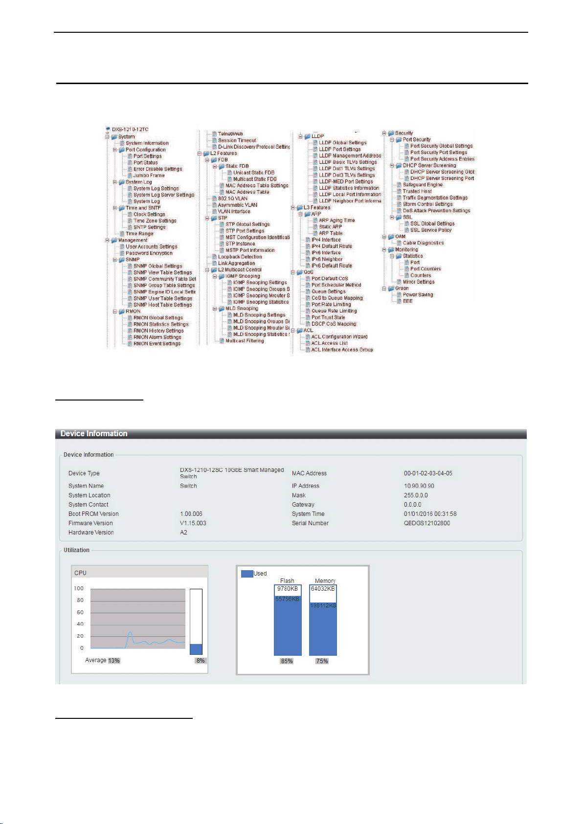
Function Tree
All configuration options on the switch are accessed through the Setup menu on the left side of the main
window. Click on the setup item that you want to configure. The following sections provide more detailed
description of each feature and function.
Figure 4.25 –Function Tree
Device Information
The Device Information provides an overview of the switch, including essential information such as firmware
& hardware information, and IP settings.
Figure 4.26 – Device Information
System > System Information
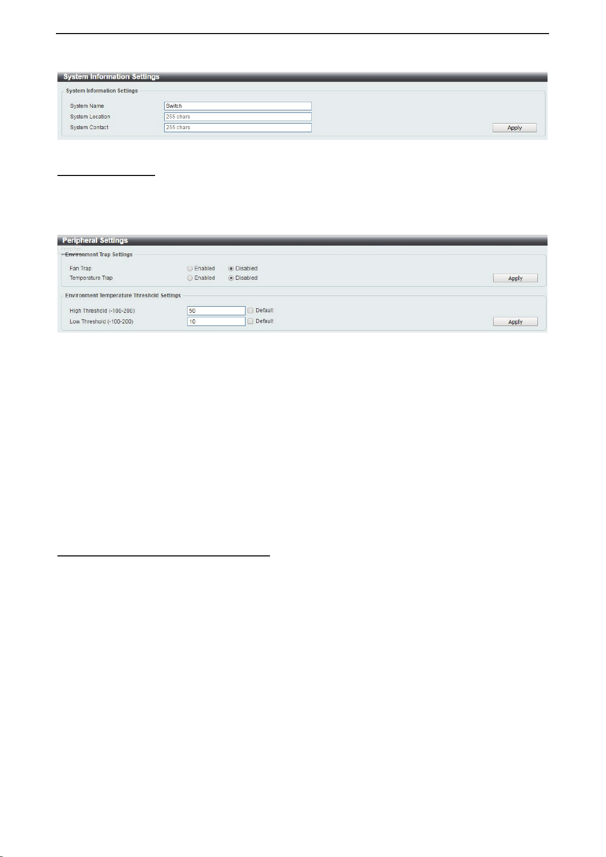
The System Setting page allows you to configure basic system information.
System Information Settings: Enter a System Name, System Location and System Contact.
D-Link DXS-1210 Series User Manual
21
Figure 4.27 – System > System Information
System > Peripheral
The Peripheral page allows user to configure the environment trap settings and environment temperature
threshold settings.
System Information Settings: Enter a System Name, System Location and System Contact.
Figure 4.28 – System > Peripheral
Environment Trap Settings:
Fan Trap: Select to enable or disable the fan trap state for waning fan event (fan failed or fan recover).
Temperature Trap: Select to enable or disable the temperature trap state for waning temperature event
(temperature exceeds the thresholds or temperature recover).
Environment Temperature Threshold Settings:
High Threshold (-100-200): Enter the high threshold value of the warning temperature setting. The range is
from -100 to 200 Celsius degree. Tick the Default check box to return to the default value.
Low Threshold (-100-200): Enter the low threshold value of the warning temperature setting. The range is
from -100 to 200 Celsius degree. Tick the Default check box to return to the default value.
Click the Apply button to accept the changes made.
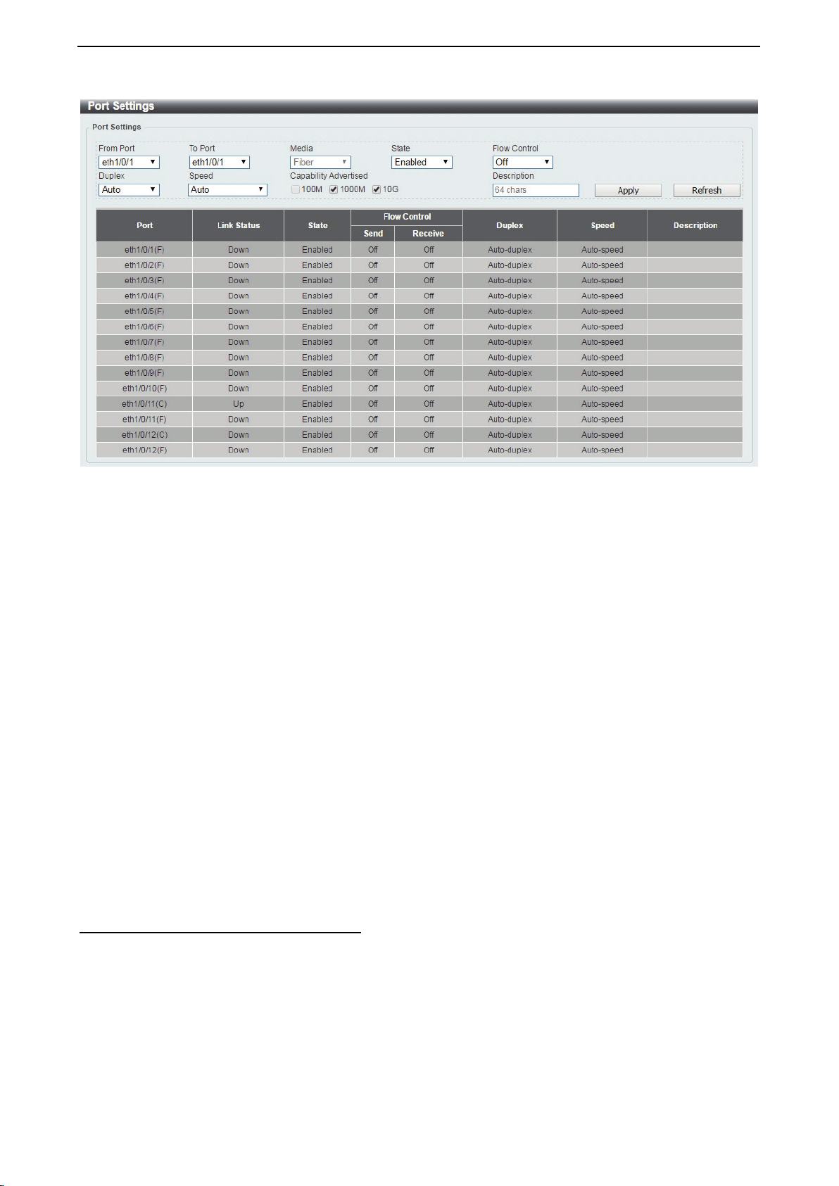
System > Port Configuration > Port Settings
In the Port Settings page, the status of all ports can be monitored and adjusted for optimum configuration.
D-Link DXS-1210 Series User Manual
22
Figure 4.29 – System > Port Configuration > Port Settings
From Port / To Port: Select the appropriate port range to be configured.
State: Enable or disable the physical port.
Auto Downgrade: To enable or disable automatically downgrading the advertised speed, in-case a link
cannot be established at the available speed.
Flow Control: Select On or Off. Ports configured for full-duplex use 802.3x flow control, half-duplex ports
use back-pressure flow control, and Auto ports use an automatic selection of the two.
Duplex: Select the duplex mode used. Options to choose from are Auto and Full.
Speed: Select the speed for the ports. The speed values are Auto, 100M, 1000M, 1000M Master, 1000M
Slave, and 10G. The Switch allows you to configure two types of Gigabit connections; 1000M Master and
1000M Slave which refer to connections running a 1000BASE-T cable for connection between the Switch
port and another device capable of a Gigabit connection. The master setting (1000M Master) will allow the
port to advertise capabilities related to duplex, speed and physical layer type. The master setting will also
determine the master and slave relationship between the two connected physical layers. This relationship is
necessary for establishing the timing control between the two physical layers. The timing control is set on a
master physical layer by a local source. The slave setting (1000M Slave) uses loop timing, where the timing
comes from a data stream received from the master. If one connection is set for 1000M Master, the other
side of the connection must be set for 1000M Slave. Any other configuration will result in a link down status
for both ports.
Capability Advertised: When the Speed is set to Auto, these capabilities are advertised during auto-
negotiation.
Description: Enter a 64 characters description for the corresponding port.
Click Apply button to save your settings.
Click the Refresh button to refresh the display table.
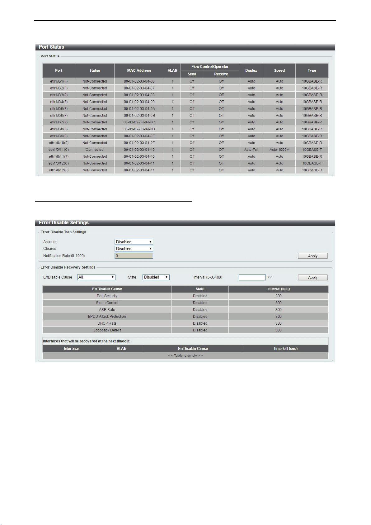
System > Port Configuration > Port Status
The Port Settings page allows you to view the Switch’s physical port status and settings. The table will
display the Port, Status, MAC Address, VLAN, Flow Control Operator, Duplex, Speed and Type.
D-Link DXS-1210 Series User Manual
23
Figure 4.30 – System > Port Configuration > Port Status
System > Port Configuration > Error Disable Settings
The Error Disable Settings page allows you to configure the sending of SNMP notifications for error disable
state.
Figure 4.31 – System > Port Configuration > Error Disable Settings
Error Disable Trap Settings:
Asserted: Select to enable or disable the notifications when entering into the error disabled state.
Cleared: Select to enable or disable the notifications when exiting from the error disabled state.
Notification Rate (0-1000): Enter the number of traps per minute. The packets that exceed the rate will be
dropped. The value is between 0 and 1000.
Click the Apply button to save your settings.
Error Disable Recovery Settings:
ErrDisable Cause: Specify the error disable causes. Options to choose from are All, Port Security, Storm
Control, ARP Rate, BPDU Protect Protection, DHCP Rate and Loopback Detect.
State: Select to enable or disable the auto-recovery for an error port caused by the specified cause.
Interval (5-586400): Enter the time interval. The values are between 5 and 586400 seconds.
Click the Apply button to save your settings.
D-Link DXS-1210 Series User Manual
24
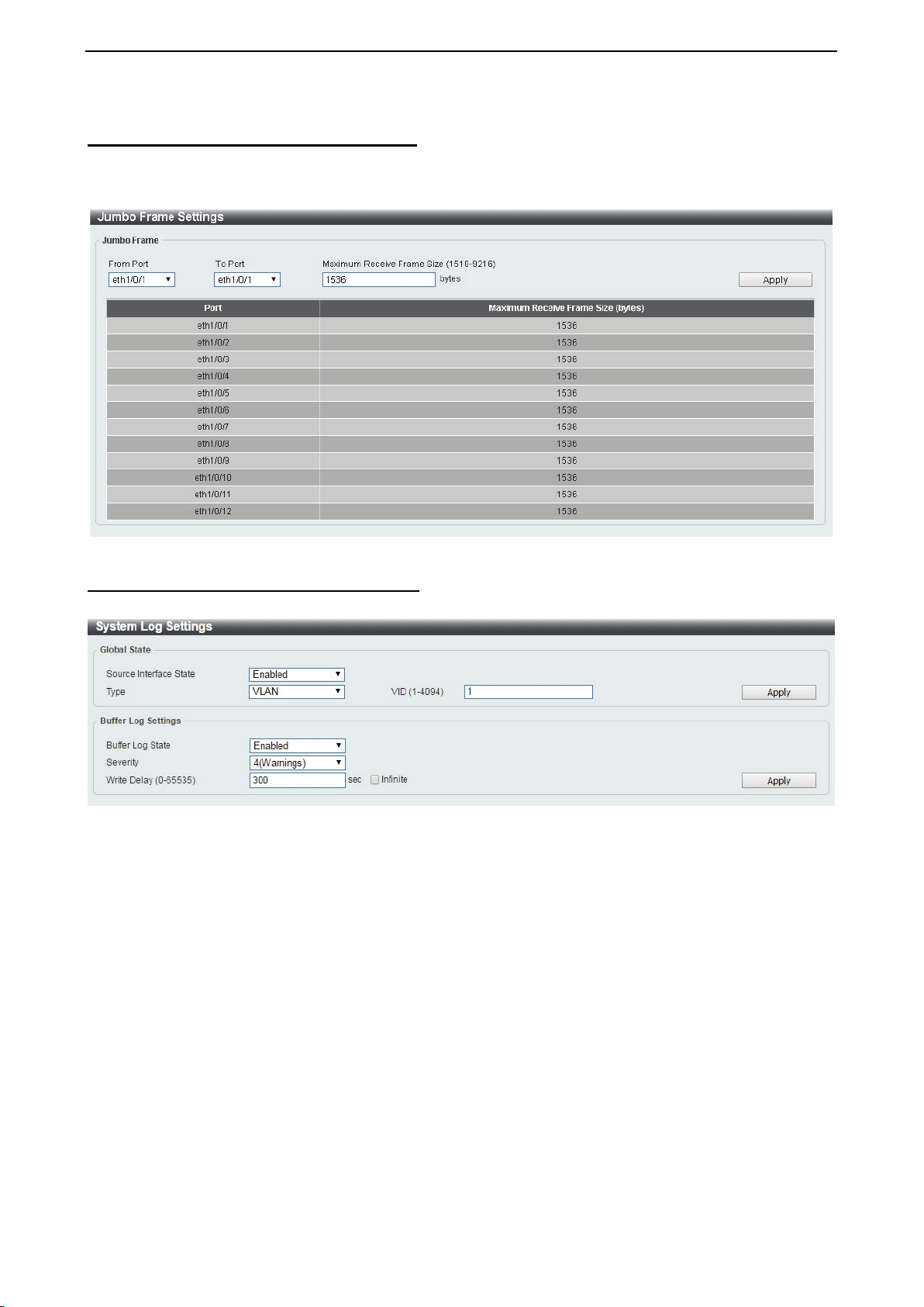
System > Port Configuration > Jumbo Frame
The Jumbo Frame page allows you to view and configure the Jumbo Frame size and settings. Jumbo frames
are Ethernet frames with more than 1,518 bytes of payload. The Switch supports jumbo frames with a
maximum frame size of up to 9216 bytes.
Figure 4.32 –System > Port Configuration > Jumbo Frame
System > System Log > System Log Settings
The System Log Settings page allows you to view and configure the system’s log settings.
Figure 4.33 – System > System Log > System Log Settings
Global State:
Source Interface State: Select to enable or disable the source interface’s global state.
Type: Select the type of interface that will be used. The default option is VLAN.
VID (1-4094): Specifies the VLAN ID. The possible range is 1 – 4094.
Click the Apply button to save your settings.
Buffer Log Settings:
Buffer Log State: Select to enable or disable the buffer log state.
Severity: Select the severity value of the type of information that will be logged. The values are 0
(Emergencies), 1 (Alerts), 2 (Critical), 3 (Errors), 4 (Warnings), 5 (Notifications), 6 (Informational), and 7
(Debugging).
Write Delay (0-65535): Enter the interval for periodic writing of the logging buffer to flash. The value is
between 0 and 65535 seconds. And default is 300 seconds. Tick the Infinite option, to disable the write delay
feature.
Click the Apply button to save your settings.
D-Link DXS-1210 Series User Manual
25
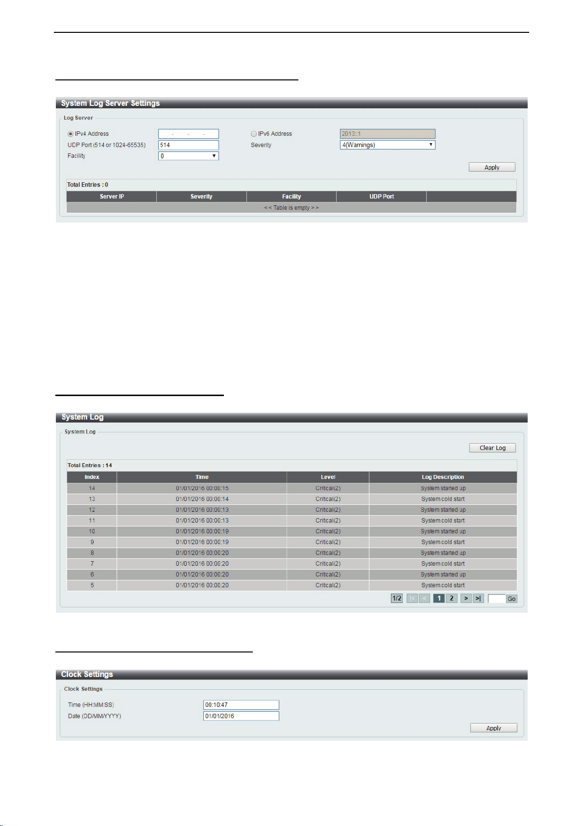
System > System Log > System Log Server Settings
The System Log Server Settings page allows you to view and configure the system log’s server settings.
Figure 4.34 – System > System Log > System Log Server Settings
IP Address: Select and enter the IPv4 address or IPv6 Address.
UDP Port (514 or 1024-65535): Enter the system log server’s UDP port number. This value must be 514 or
between 1024 and 65535. The default value is 514.
Severity: Select the severity value of the type of information that will be logged. Options to choose from are
0 (Emergencies), 1 (Alerts), 2 (Critical), 3 (Errors), 4 (Warnings), 5 (Notifications), 6 (Informational),
and 7 (Debugging).
Facility: Select the facility value. The values must be between 0 and 23.
Click the Apply button to save your settings and click the Delete button to remove the entry.
System > System Log > System Log
The System Log page displays the system logs on the Switch.
Figure 4.35 – System > System Log > System Log
System > Time and SNTP > Clock Settings
The Clock Settings page allows you to configure the time settings for the Switch.
Figure 4.36 – System > Time and SNTP > Clock Settings
D-Link DXS-1210 Series User Manual
26
Time (HH:MM:SS): Enter the current time in hours, minutes, and seconds.
Data (DD/MM/YYYY): Enter the current day, month, and year to update the system clock.
Click the Apply button to save your settings.
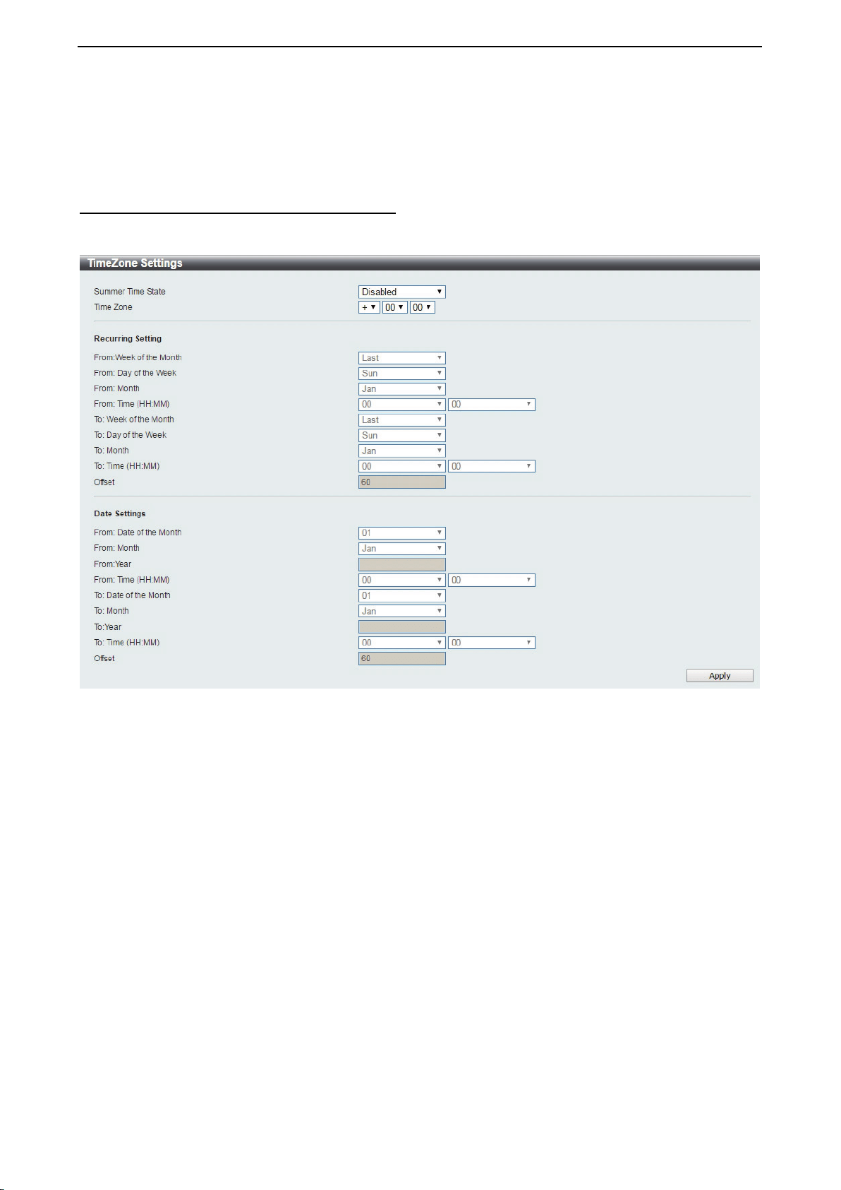
System > Time and SNTP > Time Zone Settings
The Time Zone Settings page allows you to configure time zones and Daylight Saving Time settings for
SNTP.
Figure 4.37 – System > Time and SNTP > Time Zone Settings
Summer Time State: Select Summer Time State setting. Options to choose from are Disabled, Recurring
Setting, and Date Setting.
Time Zone: Select the local time zone’s offset from Coordinated Universal Time (UTC).
The Recurring Setting can be configured below:
From: Week of the Month – Select week of the month that daylight saving time will start.
From: Day of the Week - Select day of the week that daylight saving time will start.
From: Month – Select the month that daylight time will start.
From: Time in HH MM – Select the time of the day that daylight saving time will start.
To: Week of the Month – Select week of the month that daylight saving time will end.
To: Day of the Week – Specify day of the week that daylight saving time will end.
To: Month – Select the month that daylight saving time will end.
To: Time In HH MM – Select the time of the day that daylight saving time will end.
Offset – Enter the number of minutes to add during daylight saving time. The default value is 60. The range
of this offset is 30, 60, 90 and 120.
The Date Setting can be configured below:
From: Date of the Month – Select date of the month that daylight saving time will start.
From: Month – Select the month that daylight saving time will start.
D-Link DXS-1210 Series User Manual
27
From: Year – Select the year that the daylight saving time will start.
From: Time In HH MM – Select the time of the day that daylight saving time will start.
To: Date of the Month – Select the date of the month that daylight saving time will end.
To: Month – Select the month that daylight saving time will end.
To: Year – Select the year that the daylight saving time will end.
To: Time In HH MM – Select the time of the day that daylight time will end.
Offset – Select the number of minutes to add during daylight saving
time. The default value is 60. The range
of this offset is 30, 60, 90 and 120.
Click the Apply button to save your settings.
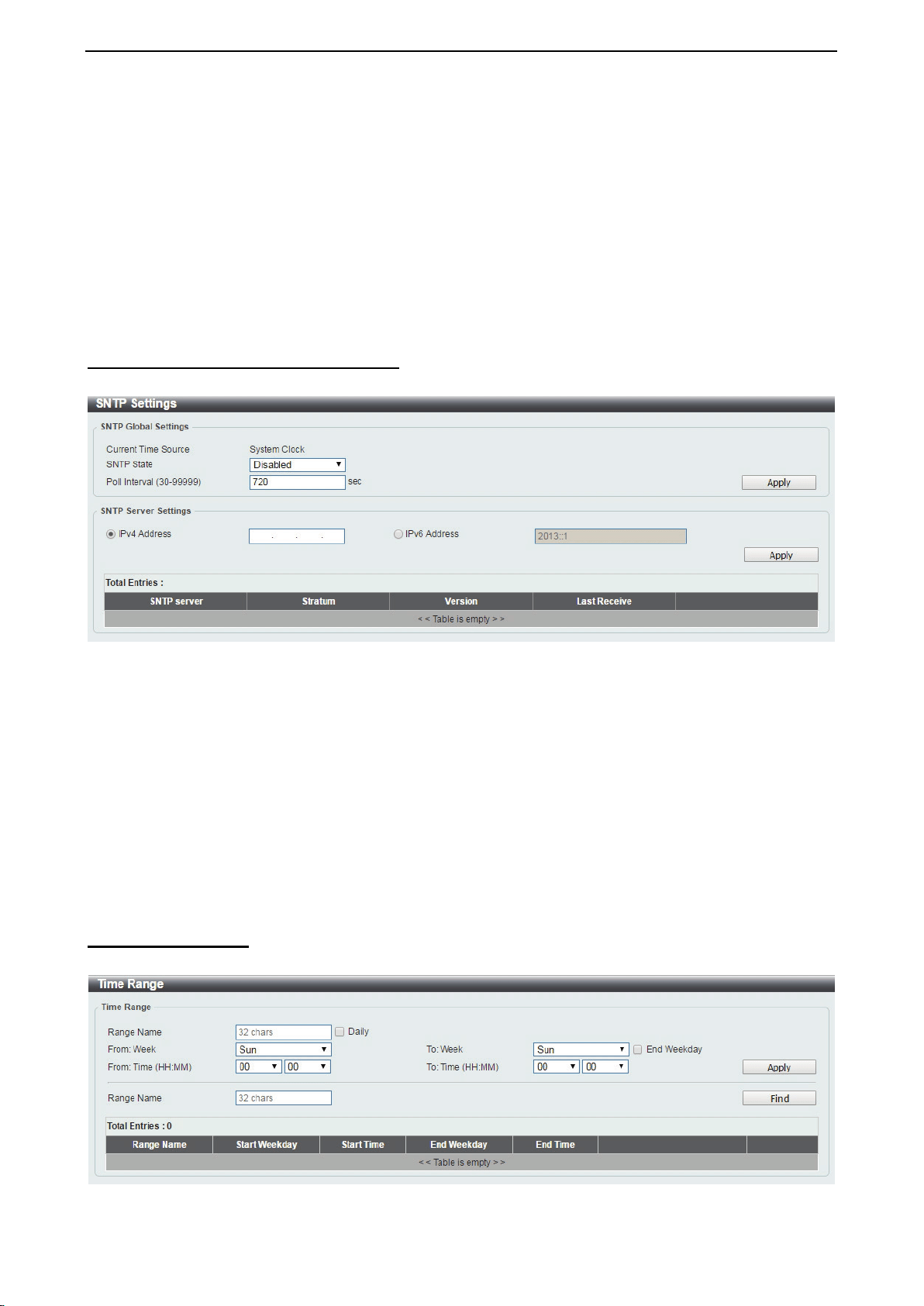
System > Time and SNTP > SNTP Settings
The SNTP Settings page allows you to configure the time settings for the Switch.
Figure 4.38 – System > Time and SNTP > SNTP Settings
SNTP Global Settings:
SNTP State: Select to enable or disable the SNTP state.
Poll Interval (30-99999): Enter the poll interval. The value is from 30 to 99999 seconds. The default interval
is 720 seconds.
Click the Apply button to save your settings.
SNTP Server Setting:
IPv4 Address: Enter the IPv4 address of the SNTP server which provides the clock synchronization.
IPv6 Address: Enter the IPv6 address of the SNTP server which provides the clock synchronization.
Click the Apply button to add the SNTP server.
System > Time Range
The Time Range page allows you to view and configure the time range settings for the Switch.
Figure 4.39 – System > Time Range
D-Link DXS-1210 Series User Manual
28
Range Name: Enter a name for the time range. The name can be up to 32 characters long.
From Week / To Week: Select the starting and ending days of the week that will be used for this time range.
Tick the Daily option to use this time range for every day of the week. Tick the End Week Day option to use
this time range from the starting day of the week until the end of the week, which is Sunday.
From Time (HH:MM) / To Time (HH:MM): Select the starting and ending time of the day that will be used for
this time range. The first drop-down menu selects the hour and the second drop-down menu selects the
minute.
Click the Apply button to save your settings.
Click the Find button to locate a specific entry based on the information entered.
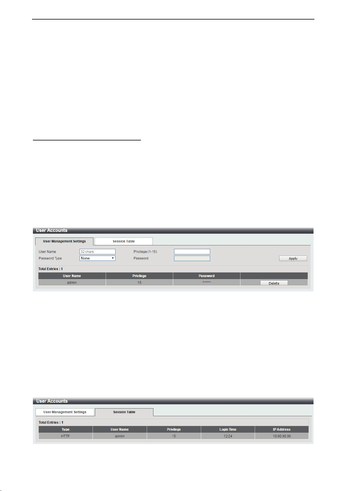
Management > User Accounts Settings
The User Accounts Settings page allows you to create and configure user accounts. Active user account
sessions can be viewed. By default, there is no user account created on the Switch.
The pre-defined user account privilege levels supported by this switch are:
• Basic User – Privilege Level 1. This user account level has the lowest priority of the user accounts. The
purpose of this type of user account level is for basic system checking.
• Operator – Privilege Level 12. This user account level is used to grant system configuration information
for users who need to change or monitor system configuration, except for security related information
such as user accounts and SNMP account settings.
• Administrator – Privilege Level 15. This administrator user account level can monitor all system
information and change any of the system configuration settings expressed in this guide.
Figure 4.40 – Management > User Accounts Settings
User Name: Enter the name of the user name. The name can be up to 32 characters long.
Privilege (1-15): Select the privilege level for this account. The value is between 1 and 15.
Password Type: Select a password type for this user account. The options are None, Plain Text, and
Encrypted.
Password: If you selected either Plain Text or Encrypted for the password type, please enter a password
for this user account.
Click the Apply button to save your settings.
Click the Delete button to remove the specified user account entry.
After clicking the Session Table tab, the following page will appear:
Figure 4.41 – Management > User Accounts Settings – Session Table
D-Link DXS-1210 Series User Manual
29
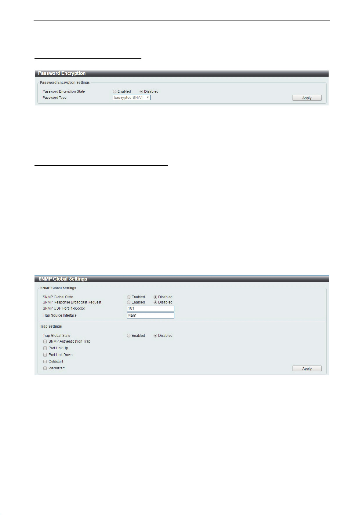
Management > Password Encryption
The Password Encryption page allows you to enable or disable password encryption.
Figure 4.42 – Management > Password Encryption
Password Encryption State: Specify to enable or disable the password encryption.
Password Type: Specify the password encryption type to Encrypted-SHA1 or Encrypted-MD5.
Click the Apply button to save your settings.
Management > SNMP > SNMP Global Settings
Simple Network Management Protocol (SNMP) is an OSI Layer 7 (Application Layer) protocol designed
specifically for managing and monitoring network devices. SNMP enables network management stations to
read and modify the settings of gateways, routers, switches, and other network devices. Use SNMP to
configure system features for proper operation, monitor performance and detect potential problems on the
Switch or your local network.
Managed devices that support SNMP include software (referred to as an agent), which runs locally on the
device. A defined set of variables (managed objects) is maintained by the SNMP agent and used to manage
the device. These objects are defined in a Management Information Base (MIB), which provides a standard
presentation of the information controlled by the on-board SNMP agent. SNMP defines both the format of the
MIB specifications and the protocol used to access this information over the network.
The default SNMP global state is disabled. Select Enable and then select Trap Settings. Click Apply to
enable the SNMP function.
Figure 4.43 – Management > SNMP > SNMP Global Settings
SNMP Global Settings:
SNMP Global State: Select to enable or disable the SNMP feature.
SNMP Response Broadcast Request: Select
to enable or disable the server to response to broadcast
SNMP GetRequest packets.
SNMP UDP Port (0-65535): Enter the SNMP UDP port number. The value is between 0 and 65535.
Trap Source Interface: Specify the interface whose IP address will be used as the source address for
sending the SNMP trap packet.
Trap Settings:
Trap Global State: Select to enable or disable the sending of all or specific SNMP notifications.
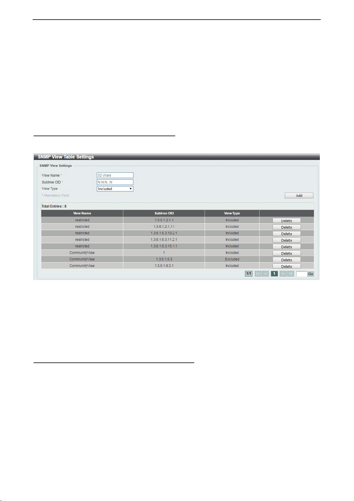
D-Link DXS-1210 Series User Manual
30
SNMP Authentication Trap:
Tick this option to control the sending of SNMP authentication failure
notifications. An authenticationFailuretrap is generated when the device receives an SNMP message that is
not properly authenticated. The authentication method depends on the version of SNMP being used. For
SNMPv1 or SNMPv2c, authentication failure occurs if packets are formed with an incorrect community string.
For SNMPv3, authentication failure occurs if packets are formed with an incorrect SHA/MD5 authentication
key.
Port Link Up: Tick this option to control the port link up notifications.
Port Link Down: Tick this option to control the port link down notifications.
Coldstart: Tick this option to control the sending of SNMP coldStart notifications.
Warmstart: Tick this option to control the sending of SNMP warmStart notifications.
Click the Apply button to save your settings.
Management > SNMP > SNMP View Table Settings
The SNMP View page allows you to define SNMP Views, which can be used to manage the MIB objects that
are accessible to a remote SNMP manager.
Figure 4.44 – Management > SNMP > SNMP View Table Settings
View Name: Create a name of the view, up to 32 characters.
Subtree OID: The Object Identifier (OID) Subtree for the view. The OID identifies an object tree (MIB tree)
that will be included or excluded from access by an SNMP manager.
View Type: Select the OIDs that can accessed by a SNMP manager.
Click Add to create a new view or Delete to remove an existing view.
Management > SNMP > SNMP Community Table Settings
The SNMP Community page allows you to set the SNMP community string of the Switch. SNMP managers
using the same community string are permitted access to the Switch's SNMP agent.
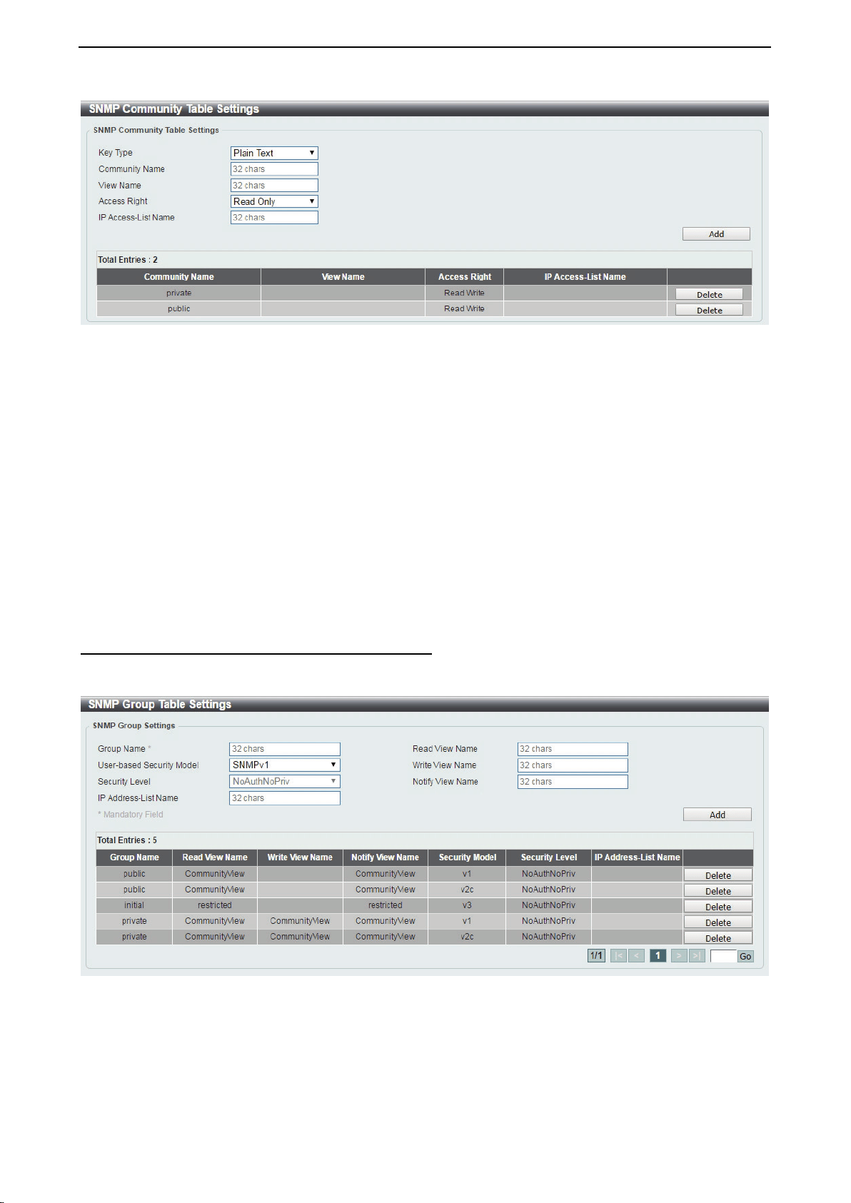
D-Link DXS-1210 Series User Manual
31
Figure 4.45 – Management > SNMP > SNMP Community Table Settings
Key Type: Select the key type for the SNMP community. Select either Plain Text or Encrypted.
Community Name: Select an alphanumeric string of up to 32 characters that is used to identify members of
an SNMP community. This string is used like a password to give remote SNMP managers access to MIB
objects in the Switch’s SNMP agent.
View Name: Enter an alphanumeric string of up to 32 characters that is used to identify the group of MIB
objects that a remote SNMP manager is allowed access to on the Switch. The view name must exist in the
SNMP View Table.
Access Right: Select the user’s access rights from the drop-down menu:
Read Only - SNMP community members can read the contents of the MIBs on the Switch.
Read Write - SNMP community members can read and write the contents of the MIBs on the Switch.
IP Access-List Name: Enter the name of the standard access list to control access to the SNMP agent
using this community string.
Click Add to a new entry based on the information entered or Delete to remove the specified entry.
Management > SNMP > SNMP Group Table Settings
The SNMP Group page allows you to manage SNMP Groups. Access to SNMP OIDs and security policies
can be controlled on a per group basis.
Figure 4.46 – Management > SNMP > SNMP Group Table Settings
Group Name: Enter a SNMP group name of up to 32 characters.
User-based Security Model: Select the SNMP security model.
SNMPv1 - SNMPv1 does not support any security features.
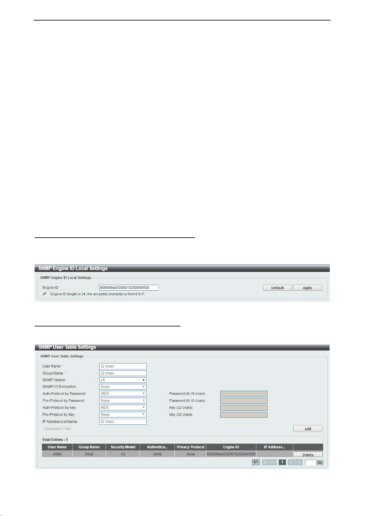
D-Link DXS-1210 Series User Manual
32
SNMPv2c - SNMPv2 supports both centralized and distributed network management strategies. It
includes improvements in the Structure of Management Information (SMI) and adds some security
features.
SNMPv3 - SNMPv3 provides secure access to devices through a combination of authentication and
encryption.
Security Level: This function is only available when you select SNMPv3 security level.
NoAuthNoPriv - No authorization and no encryption for packets sent between the Switch and SNMP
manager.
AuthNoPriv - Authorization is required, but no encryption for packets sent between the Switch and
SNMP manager.
AuthPriv – Both authorization and encryption are required for packets sent between the Switch and
SNMP manger.
IP Address-List Name:
Read View Name: Enter a SNMP group name for users that are allowed SNMP read privileges to the
Switch's SNMP agent.
Write View Name: Enter a SNMP group name for users that are allowed SNMP write privileges to the
Switch's SNMP agent.
Notify View Name: Enter a SNMP group name for users that can receive SNMP trap messages generated
by the Switch's SNMP agent.
Click the Add button to add a new entry based on the information entered.
Click the Delete button to remove the specified entry.
Management > SNMP > SNMP Engine ID Local Settings
The Engine ID is a unique identifier used to identify the SNMPv3 engine on the Switch.
Input the Engine ID then click Apply to apply the changes or click Default to change back to the default
value.
Figure 4.47 – Management > SNMP > SNMP Engine ID Local Settings
Management > SNMP > SNMP User Table Settings
The SNMP User Table Settings page allows you to manage the SNMP users that can access the Switch. It
allows you to set the Group, SNMP version, and authentication and encryption type for a user.
Figure 4.48 – Management > SNMP > SNMP User Table Settings
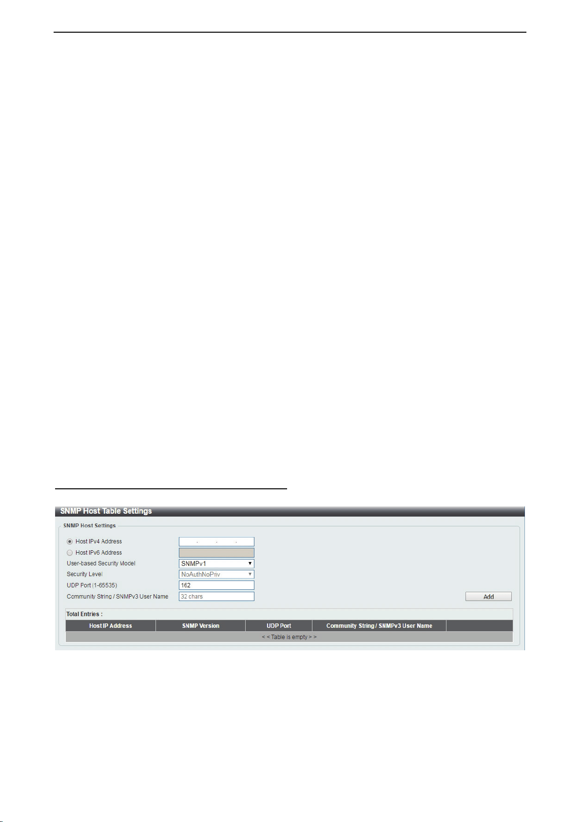
D-Link DXS-1210 Series User Manual
33
User Name: Enter a SNMP user name of up to 32 characters.
Group Name: Enter the SNMP group of the SNMP user.
SNMP Version: Select the SNMP version of the user. The options to choose are v1, v2c and v3.
SNMP V3 Encryption: When selecting v3 in the SNMP Version drop-down list, this option is available.
Options to choose from are None, Password, and Key.
Auth-Protocol by Password: Select either MD5 or SHA to be the authentication protocol. Enter a password
for SNMPv3 encryption in the right column.
MD5 – Select to use the HMAC-MD5-96 authentication level. This field will require the user to enter
a password.
SHA - Select that the HMAC-SHA authentication protocol will be used. This field will require the user
to enter a password.
Priv-Protocol by Password: Select either None or DES56 and then enter a password for SNMPv3
encryption in the right column.
None – Select to not use any authorization.
DES56 – Select to use DES 56-bit encryption, based on the CBC-DES (DES-56) standard. This field
will require you to enter a password.
Auth-Protocol by Key: Select either MD5 or SHA to be the authentication protocol. Enter a key for SNMPv3
encryption in the right column.
MD5 – Select to use the HMAC-MD5-96 authentication level. This field will require the user to enter
a key.
SHA – Select to use the HMAC-SHA authentication protocol. This field will require you to enter a key.
Priv-Protocol by Key: Select either None or DES56 and then enter a password for SNMPv3 encryption in
the right column.
None – Select to not use any authorization.
DES56 – Select to use DES 56-bit encryption, based on the CBC-DES (DES-56) standard. This field
will require the user to enter a key.
IP Address-List Name: Enter the standard IP Access Control List (ACL) to associate with the user.
Click Add to create a new SNMP user account or click Delete to remove any existing data.
Management > SNMP > SNMP Host Table Settings
The SNMP Host Table Settings page allows you to configure the SNMP trap recipients.
Figure 4.49 – Management > SNMP > SNMP Host Table Settings
Host IPv4/IPv6 Address: Select IPv4 or IPv6 and specify the IP address of SNMP management host.
User-based Security Model: Specify the SNMP version to be used to the management host. The options
are SNMPv1, SNMPv2C and SNMPv3.
Security Level: When selecting SNMPv3 in the User-based Security Model drop-down list, this option is
available.
NoAuthNoPriv – Select to have no authorization and no encryption of packets sent between the
Switch and a remote SNMP manager.
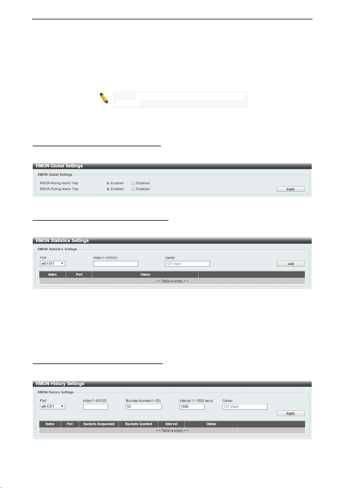
D-Link DXS-1210 Series User Manual
34
AuthNoPriv – Select to require authorization, but with no encryption of packets sent between the
Switch and a remote SNMP manager.
AuthPriv – Select to require authorization, and packets sent between the Switch and a remote
SNMP manger will be encrypted.
UDP Port (0-65535): Enter the UDP port number. The default trap UDP port number is 162. The range of
UDP port numbers is from 0 to 65535.
NOTE: Some port numbers may conflict with other
protocols.
Community String / SNMPv3 User Name: Enter the community string to be sent with the notification packet.
Click Add to create a new SNMP host, Delete to remove an existing host.
Management > RMON > RMON Global Settings
You can enable and disable remote monitoring (RMON) status for the SNMP function on the Switch. In
addition, RMON Rising and Falling Alarm Traps can be enabled and disabled.
Figure 4.50 – Management > RMON > RMON Global Settings
Management > RMON > RMON Statistics Settings
The RMON Statistics Settings page displays RMON Ethernet statistics and allows you to configure the
settings.
Figure 4.51 – Management > RMON > RMON Statistics Settings
The RMON Ethernet Statistics Configuration contains the following fields:
Port: Select the port from which the RMON information was taken.
Index (1 - 65535): Indicates the RMON Ethernet Statistics entry number.
Owner: Displays the RMON station or user that requested the RMON information.
Click Add to activate your entry or click to renew the details collected and displayed.
Management > RMON > RMON History Settings
The RMON History Settings page contains information about samples of data taken from ports, such as
interface definitions or polling periods.
Figure 4.52 – Management > RMON > RMON History Settings
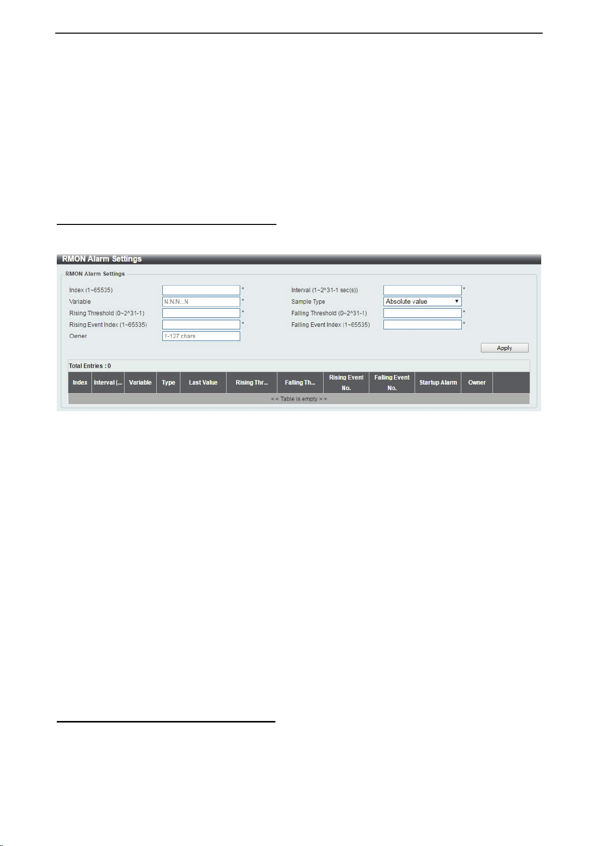
D-Link DXS-1210 Series User Manual
35
The History Control Configuration contains the following fields:
Port: Select the port from which the RMON information was taken.
Index (1 - 65535): Indicates the history control entry number.
Buckets Requested (1 ~ 50): Enter the number of buckets that the device saves.
Interval (1 ~ 3600 secs): Indicates in seconds the time period that samplings are taken from the ports. The
field range is 1-3600. The default is 1800 seconds (equal to 30 minutes).
Owner: Displays the RMON station or user that requested the RMON information.
Click Apply to activate your entry.
Management > RMON > RMON Alarm Settings
The RMON Alarm Settings page allows you to configure the network alarms. Network alarms occur when a
network problem or event is detected.
Figure 4.53 – Management > RMON > RMON Alarm Settings
The configuration contains the following fields:
Index (1 - 65535): Enter a specific alarm.
Variable: Select the selected MIB variable value.
Rising Threshold (0 ~ 2^31-1): Displays the rising counter value that triggers the rising threshold alarm.
Rising Event Index (1 ~ 65535): Displays the event that triggers the specific alarm. The possible field
values are user defined RMON events.
Owner: Displays the device or user that defined the alarm.
Interval (1 ~ 2^31-1): Defines the alarm interval time in seconds.
Sample type: Defines the sampling method for the selected variable and comparing the value against the
thresholds. The possible field values are:
Delta value – Subtracts the last sampled value from the current value. The difference in the values
is compared to the threshold.
Absolute value – Compares the values directly with the thresholds at the end of the sampling
interval.
Falling Threshold (0 ~ 2^31-1): Displays the falling counter value that triggers the falling threshold alarm.
Falling Event Index (1 ~ 65535): Displays the event that triggers the specific alarm. The possible field
values are user defined RMON events.
Click Apply to activate your alarm entry.
Management > RMON > RMON Event Settings
The RMON Event Settings page contains fields for defining, modifying and viewing RMON event statistics.
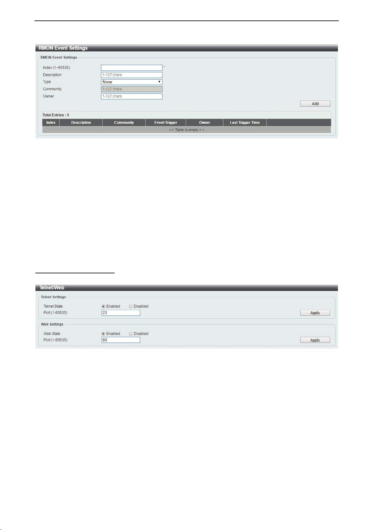
D-Link DXS-1210 Series User Manual
36
Figure 4.54 – Management > RMON > RMON Event Settings
The RMON Events Page contains the following fields:
Index (1~ 65535): Enter the event index.
Description: Enter an event description.
Type: Select the event type. The possible values are:
None – Indicates that no event occurred.
Log – Indicates that the event is a log entry.
SNMP Trap – Indicates that the event is a trap.
Log and Trap – Indicates that the event is both a log entry and a trap.
Community: Enter the community to which the event belongs.
Owner: Enter the time that the event occurred.
Click Add to add a new RMON event.
Management > Telnet/Web
The Telnet/Web page allows you to configure Telnet and Web settings on the Switch.
Figure 4.55 – Management > Telnet/Web
Telnet Settings:
Telnet State: Select to enable or disable the configuration through Telnet.
Port (1-65535): Enter the TCP port number used for Telnet management of the Switch. The standard TCP
port for the Telnet protocol is 23.
Click Apply to save your settings.
Web Settings:
Web State: Select to enable or disable Web-based configuration.
Port (1-65535): Enter the TCP port number used for Telnet management of the Switch. The standard TCP
port for the HTTP protocol is 80.
Click the Apply button to save your settings.
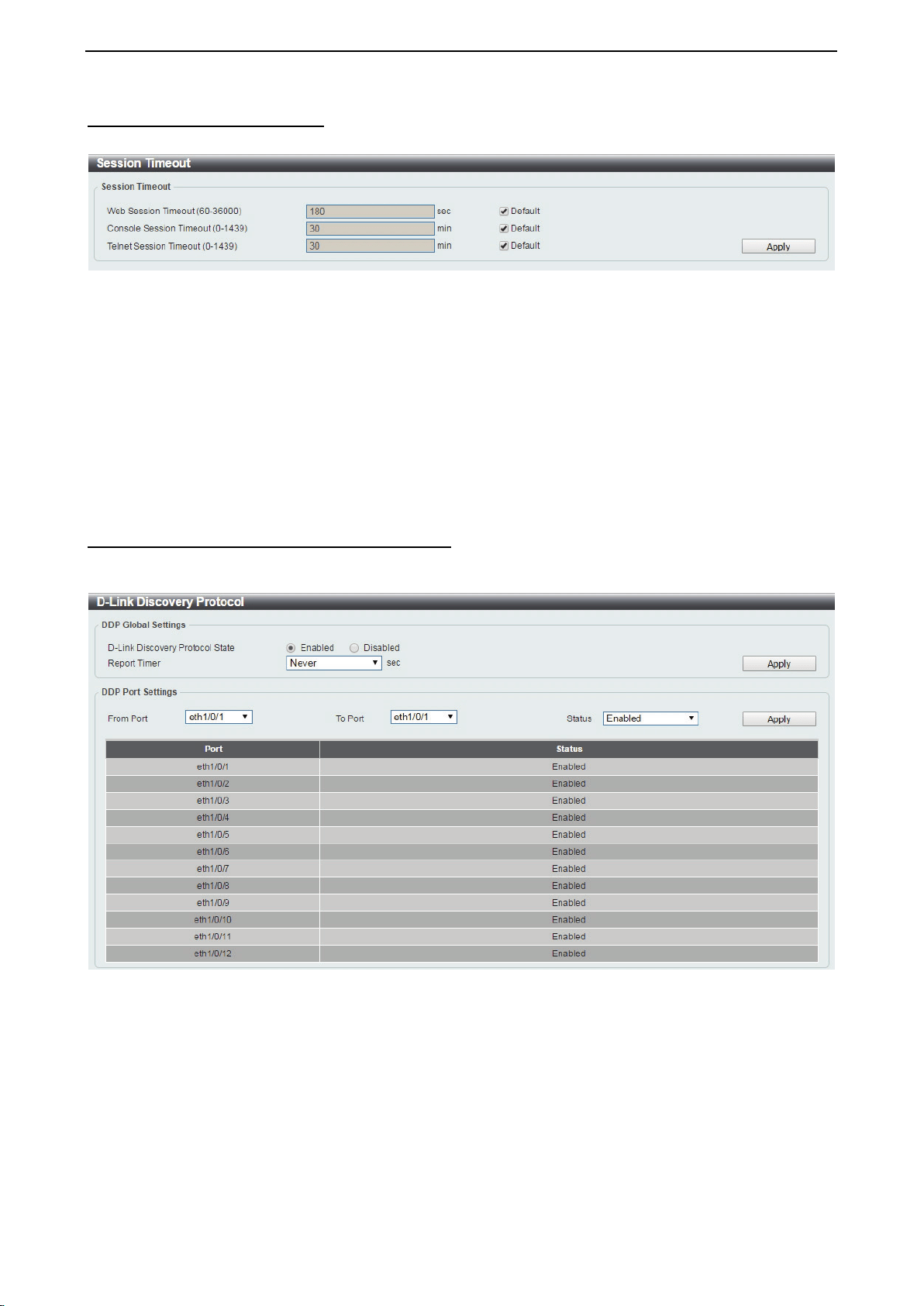
D-Link DXS-1210 Series User Manual
37
Management > Session Timeout
The Session Timeout page allows you to configure the session timeout on the Switch.
Figure 4.56 – Management > Session Timeout
Web Session Timeout (60-36000): Enter the time in seconds of the web session timeout. Tick the Default
check box.
Console Session Timeout (0-1439): Enter the time in minutes of the Console session timeout. Tick the
Default check box to return to the default setting. The value is from 0 to 1439 minutes. 0 means never
timeout. The default value is 30 minutes.
Telnet Session Timeout (0-1439): Enter the time in minutes of the Telnet session timeout. Tick the Default
check box to return to the default setting. The value is from 0 to 1439 minutes. 0 means never timeout. The
default value is 30 minutes.
Click the Apply button to save your settings.
Management > D-Link Discover Protocol Settings
The D-Link Discover Protocol Settings page allows you to configure and display D-Link Discovery Protocol
(DDP).
Figure 4.57 – Management > D-Link Discover Protocol Settings
D-Link Discovery Protocol State: Enter the enable or disable the D-Link Discovery Protocol state.
Report Timer: Specify the interval in seconds between two consecutive DDP report messages. Options to
choose from are 30, 60, 90,120, and Never.
DDP Port Settings:
From Port / To Port: Enter the appropriate port range used for the configuration.
State: Select to enable or disable the DDP port state.
Click the Apply button to save your settings.
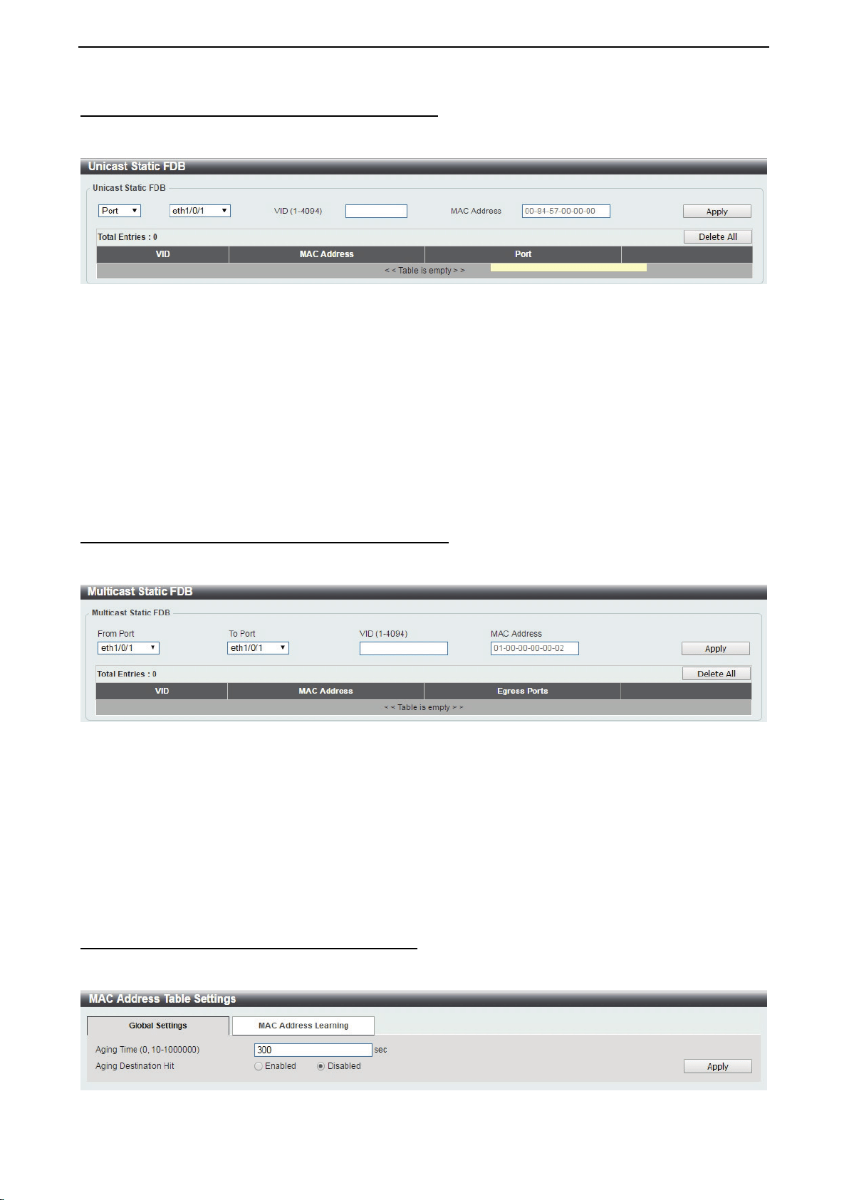
D-Link DXS-1210 Series User Manual
38
L2 Features > FDB > Static FDB > Unicast Static FDB
The Unicast Static FDB page allows you to view and configure the static unicast forwarding settings on the
Switch.
Figure 4.58 – L2 Features > FDB > Static FDB > Unicast Static FDB
Port / Drop: Allows the selection of the port number on which the MAC address entered resides. This option
could also drop the MAC address from the unicast static FDB. When selecting Port, select the switch unit
and port number.
VID (1-4094): Enter the VLAN ID on which the associated unicast MAC address resides.
MAC Address: Enter the MAC address to which packets will be statically forwarded or dropped. This must
be a unicast MAC address.
Click the Apply button to save your settings or click the Delete All button to delete all the entries found in the
display table.
Enter a page number and click the Go button to navigate to a specific page when multiple pages exist.
L2 Features > FDB > Static FDB > Multicast Static FDB
The Multicast Static FDB page allows you to view and configure the static multicast forwarding settings on
the Switch.
Figure 4.59 – L2 Features > FDB > Static FDB > Multicast Static FDB
From Port / To Port: Enter the appropriate port range used for the configuration.
VID (1-4094): Enter the VLAN ID of the VLAN the corresponding MAC address belongs to.
MAC Address: Enter the static destination MAC address of the multicast packets. This must be a multicast
MAC address. The format of the destination MAC address is 01-XX-XX-XX-XX-XX.
Click the Apply button to save your settings. And click the Delete All button to remove all the entries. Click
the Delete button to remove the specific entry.
Enter a page number and click the Go button to navigate to a specific page when multiple pages exist.
L2 Features > FDB > MAC Address Table Settings
The MAC Address Table Settings page allows you to view and configure the MAC address table’s global
settings.
Figure 4.60 – L2 Features > FDB > MAC Address Table Settings – Global Setting
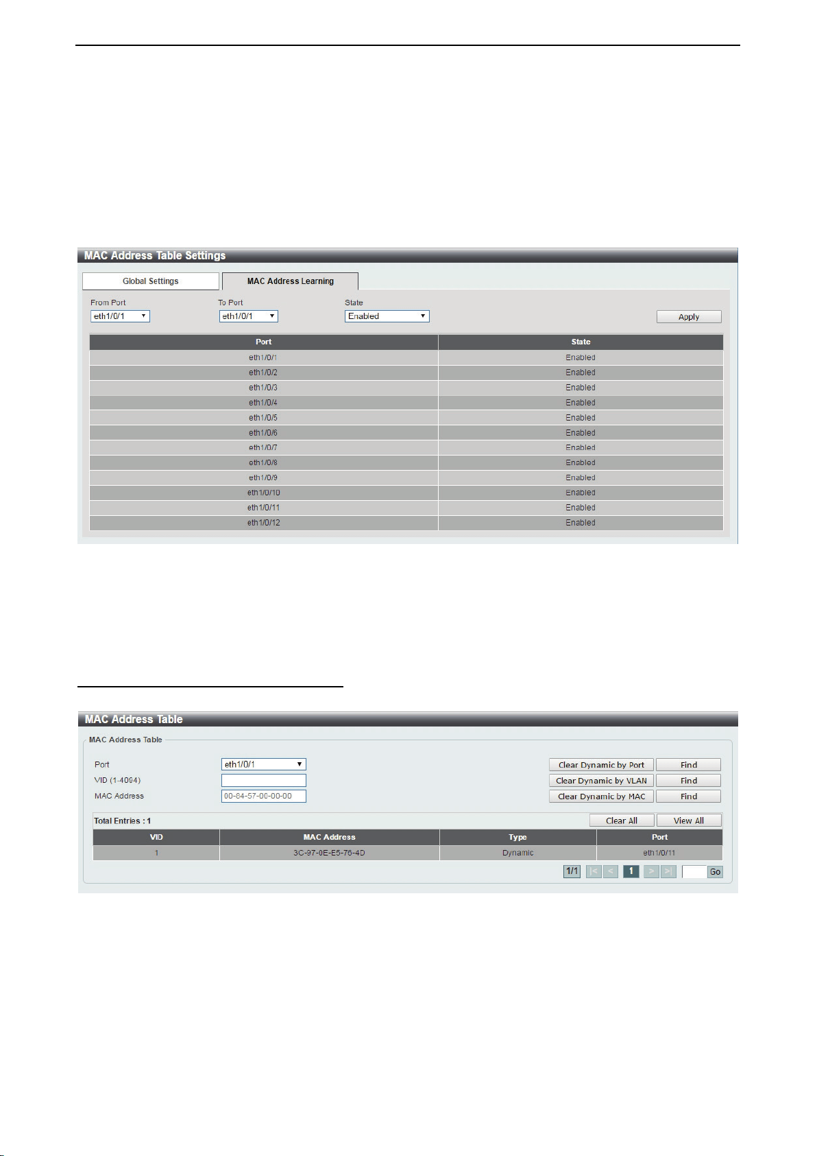
D-Link DXS-1210 Series User Manual
39
Aging Time: Enter the MAC address table’s aging time value. This value must be between 10 and 1000000
seconds. Entering 0 will disable MAC address aging. By default, this value is 300 seconds.
Aging Destination Hit: Select to enable or disable the aging destination hit function.
Click the Apply button to save your settings.
After clicking the MAC Address Learning tab, the following page will appear.
Figure 4.61 – L2 Features > FDB > MAC Address Table Settings – MAC Address Learning
From Port / To Port: Enter the range of ports that will be used for this configuration.
State: Select to enable or disable the MAC address learning function on the specified ports.
Click the Apply button to save your settings.
L2 Features > FDB > MAC Address Table
The MAC Address Table page allows you to view the entries listed in the MAC address table.
Figure 4.62 – L2 Features > FDB > MAC Address Table
Port: Select the port that will be used for this configuration.
VID (1-4094): Enter the VLAN ID that will be used for this configuration.
MAC Address: Enter the MAC address that will be used for this configuration
Click the Find button to locate a specific entry based on the information entered.
Click the Clear Dynamic by Port button to clear the dynamic MAC address listed on the corresponding port.
Click the Clear Dynamic by VLAN button to clear the dynamic MAC address listed on the corresponding
VLAN.
Click the Clear Dynamic by MAC button to clear the dynamic MAC address entered.
Click the Find button to locate a specific entry based on the information entered.
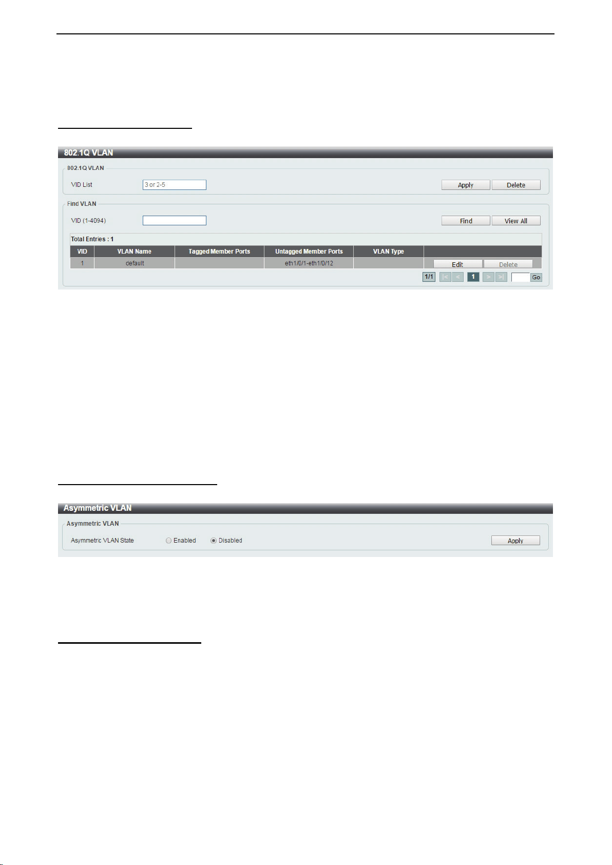
D-Link DXS-1210 Series User Manual
40
Click the Clear All button to clear all dynamic MAC addresses.
Click the View All button to display all the MAC addresses recorded in the MAC address table.
L2 Features > 802.1Q VLAN
The 802.1Q VLAN page allows you to view and configure the VLAN settings on this switch.
Figure 4.63 – L2 Features > 802.1Q VLAN
802.1Q VLAN:
VID List: Enter the VLAN ID list that will be created.
Click the Apply button to save your settings.
Click the Delete button to remove the specific entry.
Find VLAN:
VID (1-4094): Enter the VLAN ID to be displayed.
Click the Find button to locate a specific entry based on the information entered.
Click the View All button to locate all the entries.
Click the Edit button to re-configure the specific entry.
Enter a page number and click the Go button to navigate to a specific page when multiple pages exist.
L2 Features > Asymmetric VLAN
The Asymmetric VLAN page allows you to configure the asymmetric VLAN function on this switch.
Figure 4.64 – L2 Features > Asymmetric VLAN
Asymmetric VLAN State: Select to enable or disable the Asymmetric VLAN function.
Click the Apply button to save your settings.
L2 Features > VLAN Interface
The VLAN Interface page allows you to view and configure the VLAN interface settings on this switch.
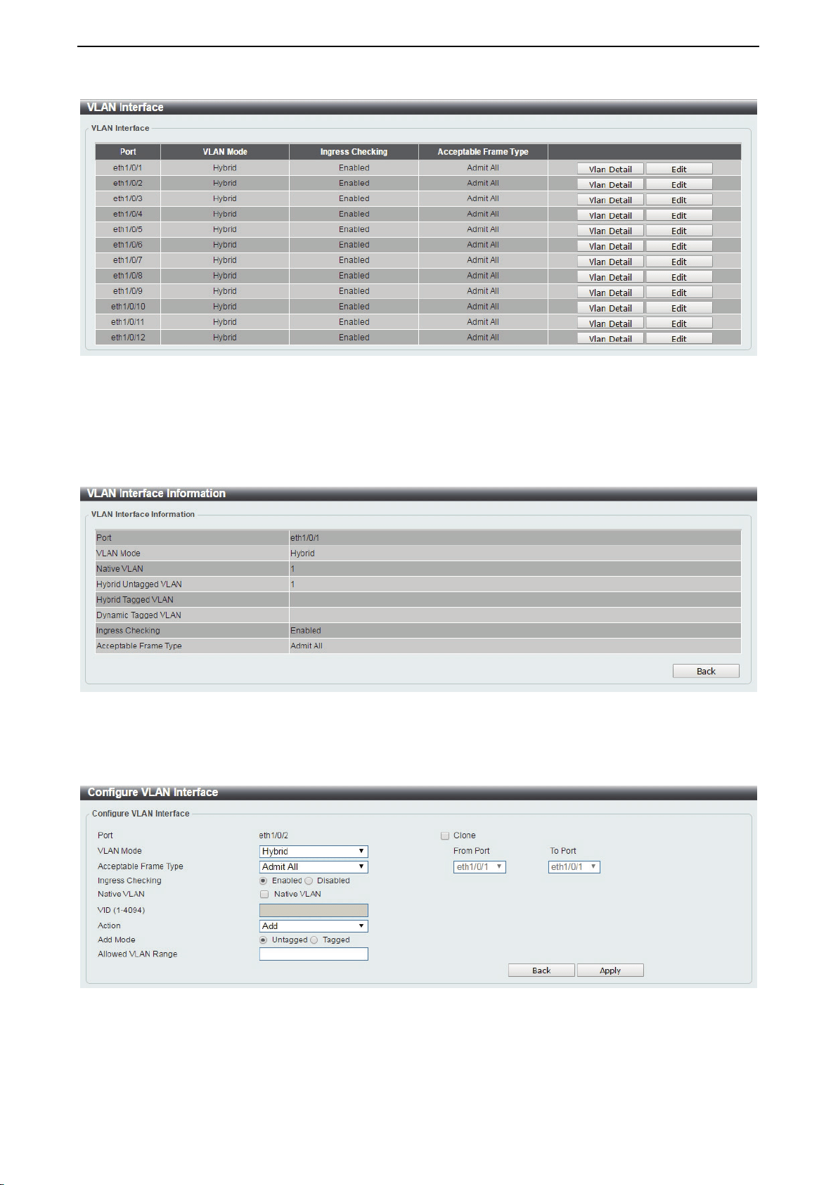
D-Link DXS-1210 Series User Manual
41
Figure 4.65 – L2 Features > VLAN Interface
Unit: Select the switch unit that will be used for this configuration.
Click the VLAN Detail button to view more detailed information about the VLAN on the specific interface.
Click the Edit button to re-configure the specific entry.
After clicking the VLAN Detail button, the following page will appear:
Figure 4.66 – L2 Features > VLAN Interface – VLAN Detail
After clicking the Edit button, the following window will appear. This is a dynamic window that will change
when a different VLAN Mode is selected. When Access was selected as the VLAN Mode, the following
page will appear.
Figure 4.67 – L2 Features > VLAN Interface – VLAN Detail
Port: Display the VLAN port number.
VLAN Mode: Select the VLAN mode option. Options to choose from are Access, Hybrid, and Trunk.
Acceptable Frame Type: Select the acceptable frame type behavior option. Options to choose from are
Tagged Only, Untagged Only, and Admit All.
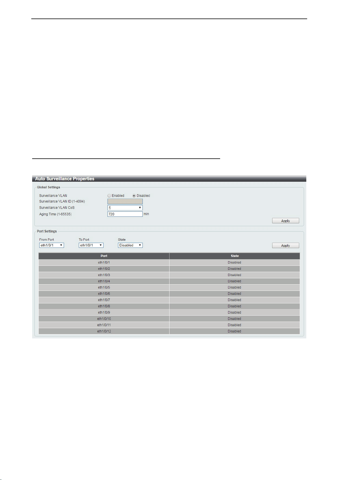
D-Link DXS-1210 Series User Manual
42
Ingress Checking: Select to enable or disable the ingress checking function.
Native VLAN: Tick the option to enable the native VLAN function.
VID (1-4094): After ticking the Native VLAN check box, this option will be available. Enter the VLAN ID used
for this configuration. This value must be between 1 and 4094.
Action: Select the action that will be taken here. Options to choose from are Add, Remove, Tagged, and
Untagged.
Add Mode: Select whether to add an Untagged or Tagged parameters.
Allowed VLAN Range: Enter the allowed VLAN range information.
Clone: Tick the Clone check box to copy the configuration to specified ports.
From Port / To Port: Copy the configuration of VLAN interface for specified port ranges.
Click the Apply button to save your settings.
Click the Back button to return to the previous page.
L2 Features > Auto Surveillance VLAN > Auto Surveillance Properties
The Auto Surveillance Properties page is used to configure the auto surveillance VLAN global settings and
display the ports surveillance VLAN information.
Figure 4.68 – L2 Features > Auto Surveillance VLAN > Auto Surveillance Properties
Global Settings:
Surveillance VLAN: Specify to enable or disable the surveillance VLAN state.
Surveillance VLAN ID: Enter the surveillance VLAN ID. The range is from 1 to 4094.
Surveillance VLAN CoS: Specify the priority of the surveillance VLAN from 0 to 7.
Aging Time: Specify the aging time of the surveillance VLAN. The range is from 1 to 65535 minutes. The
default value is 720 minutes. The aging time is used to remove a port from surveillance VLAN if the port is an
automatic surveillance VLAN member. When the last surveillance device stops sending traffic and the MAC
address of this surveillance device is aged out, the surveillance VLAN aging timer will be started. The port
will be removed from the surveillance VLAN after expiration of surveillance VLAN aging timer. If the
surveillance traffic resumes during the aging time, the aging counter will be reset and the timer will stop.
Click the Apply button to save your settings.
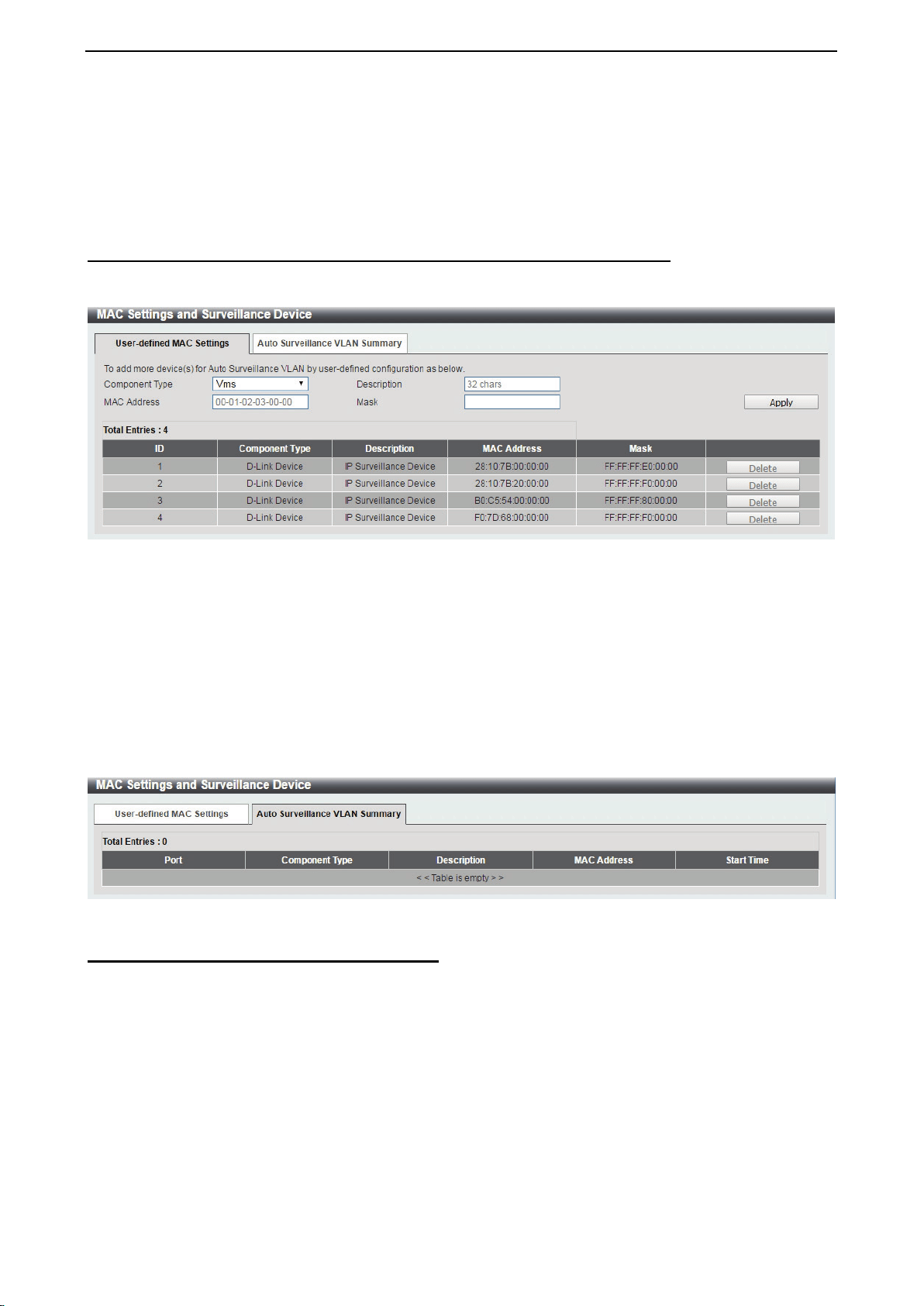
D-Link DXS-1210 Series User Manual
43
Port Settings:
From Port/To Port: Specify the port range used for the configuration.
State: Specify to enable or disable the state of the port.
Click the Apply button to save your settings.
L2 Features > Auto Surveillance VLAN > MAC Settings and Surveillance Device
The MAC Settings and Surveillance Device page is used to configure the user-defined surveillance device
OUI and display the surveillance VLAN information.
Figure 4.69 – L2 Features > Auto Surveillance VLAN > MAC Settings and Surveillance Device
Component Type: Specify the surveillance component type. Option to choose from are Vms, VmsClient,
VideoEncoder, NetworkStorage and Other.
Description: Enter the description for the user-defined OUI with a maximum of 32 characters.
MAC Address: Enter the OUI MAC address.
Mask: Enter the OUI MAC address matching bitmask.
Click the Apply button to accept the changes made.
Click the Delete button to remove the specified entry.
After click the Auto Surveillance VLAN Summary tab, the following page will appear.
Figure 70 – L2 Features > Auto Surveillance VLAN > MAC Settings and Surveillance Device
L2 Features > Voice VLAN > Voice VLAN Global
The Voice VLAN is a VLAN used to carry voice traffic from an IP phone. As the sound quality of Voice over
IP, is sensitive to delay Quality of service (QoS) for voice traffic should be configured to ensure that voice
traffic is handled with a higher priority.
The switches determine whether a received packet is a voice packet by checking its source MAC address. If
the source MAC addresses of a packet complies with the organizationally unique identifier (OUI) addresses
configured by the system, the packets are determined as voice packets and transmitted in voice VLAN.
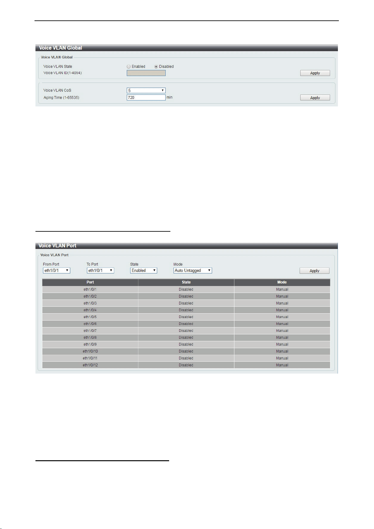
D-Link DXS-1210 Series User Manual
44
Figure 4.71 – L2 Features > Voice VLAN > Voice VLAN Global Settings
Voice VLAN State: Select to enable or disable Voice VLAN.
VLAN ID (1-4094): Enter the voice VLAN ID. The value is range from 1 to 4094.
Voice VLAN CoS: Specify the priority of the voice VLAN from 0 to 7.
Aging Time: Enter the aging time of surveillance VLAN. The range is from 1 to 65535 minutes. The default
value is 720 minutes. The aging time is used to remove a port from voice VLAN if the port is an automatic
VLAN member. When the last voice device stops sending traffic and the MAC address of this voice device is
aged out, the voice VLAN aging timer will be started. The port will be removed from the voice VLAN after
expiration of voice VLAN aging timer. If the voice traffic resumes during the aging time, the aging counter will
be reset and the timer will stop.
Click the Apply button to accept the changes made.
L2 Features > Voice VLAN > Voice VLAN Port
The Voice VLAN Port page is used to show the ports voice VLAN information.
Figure 4.72 – L2 Features > Voice VLAN > Voice VLAN Port
From Port / To Port: Select the appropriate port range used for the configuration.
State: Specify to enable or disable the state of the port.
Mode: Specify the mode of the port. Options to choose from are Auto Untagged, Auto Tagged, and
Manual.
Click the Apply button to accept the changes made.
L2 Features > Voice VLAN > Voice VLAN OUI
The Voice VLAN OUI page is used to configure the user-defined voice traffic’s OUI. The OUI is used to
identify voice traffic. There are a number of pre-defined OUIs. The user can further define the user-defined
OUIs if needed. The user-defined OUI cannot be the same as the pre-defined OUI.
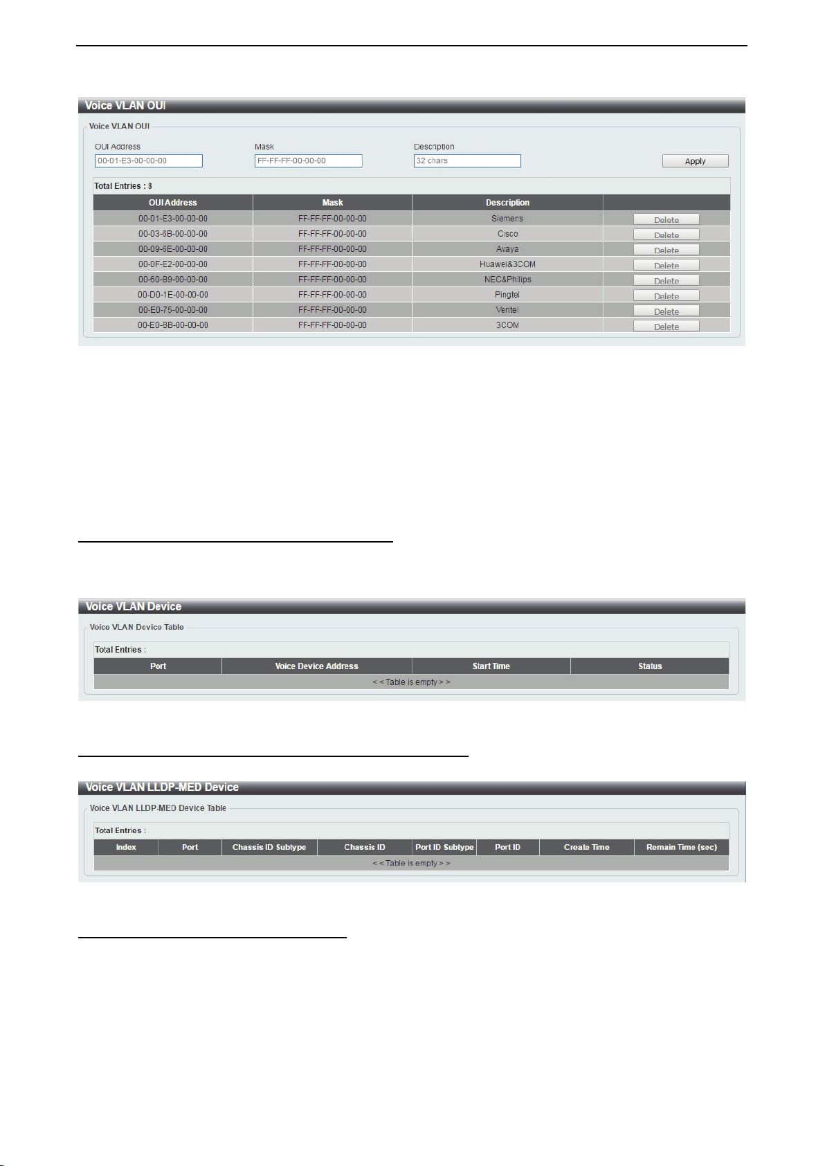
D-Link DXS-1210 Series User Manual
45
Figure 4.73 – L2 Features > Voice VLAN > Voice VLAN OUI
OUI Address: Specify the OUI MAC address.
Mask: Specify the OUI MAC address matching bitmask.
Description: Enter the description for the user-defined OUI with a maximum of 32 characters.
Click the Apply button to accept the changes made.
Click the Delete button to remove the specified entry.
L2 Features > Voice VLAN > Voice VLAN Device
The Voice VLAN Device page is used to show voice devices that are connected to the Switch. The Start
Time is the time when the device was detected on the port and the Status displays the voice VLAN status of
the port.
Figure 4.74 – L2 Features > Voice VLAN > Voice VLAN Device
L2 Features > Voice VLAN > Voice VLAN LLDP-MED Device
The page displays the Voice VLAN LLDP-MED voice devices connected to the Switch.
Figure 4.75 – L2 Features > Voice VLAN > Voice VLAN LLDP-MED Device
L2 Features > STP > STP Global Settings
The Switch implements three versions of the Spanning Tree Protocol: Rapid Spanning Tree Protocol (RSTP)
as defined by IEEE 802.1w, a version compatible with the IEEE 802.1D STP and Multiple Spanning Tree
Protocol (MSTP), as defined by IEEE802.1. RSTP can operate with legacy equipment implementing IEEE
802.1D, however the advantages of using RSTP will be lost.
The Rapid Spanning Tree Protocol (RSTP) evolved from the 802.1D STP standard and was developed in
order to overcome some of the limitations of STP that impede the function of some recent switching
innovations. The basic function and much of the terminology is the same and most of the settings configured
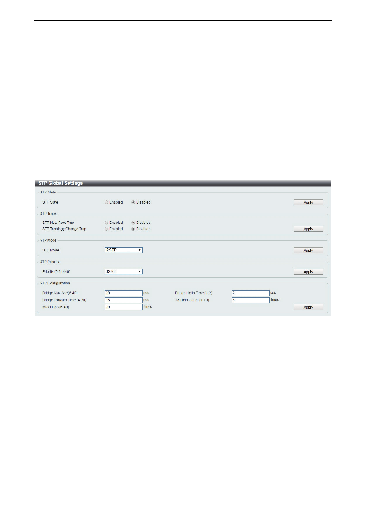
D-Link DXS-1210 Series User Manual
46
for STP are also used for RSTP. This section introduces some new Spanning Tree concepts and illustrates
the main differences between the two protocols.
The IEEE 802.1 Multiple Spanning Tree (MSTP) provides various load balancing techniques by allowing
multiple VLANs to be mapped to a single spanning tree instance, providing multiple pathways across the
network. For example, while port A is blocked in one STP instance, the same port can be placed in the
Forwarding state in another STP instance.
By default, Rapid Spanning Tree is disabled. If enabled, the Switch will listen for Bridge Protocol Data Unit
(BPDU) packets and its accompanying Hello packet. The BPDU packets are sent even if a BPDU packet is
not received. Therefore, each link between bridges is sensitive to the status of the link. Ultimately this
difference results in faster detection of failed links, and therefore faster topology adjustment.
By default Multiple Spanning Tree is enabled. It will tag BPDU packets to receiving devices and distinguish
spanning tree instances, spanning tree regions and the VLANs associated with them.
After enabling STP, configure the STP Global Settings (shown below).
Figure 4.76 – L2 Features > STP > STP Global Settings
STP State:
STP State: Select to enable or disable the Spanning Tree Protocol.
Click the Apply button to save your settings.
STP Traps:
STP New Root Trap: Select to enable or disable the STP new root trap option.
STP Topology Change Trap: Select to enable or disable the STP topology change trap option.
Click the Apply button to save your settings.
STP Mode:
STP Mode: Select the STP mode. The options to choose from are MSTP, RSTP and STP.
Click the Apply button to save your settings.
STP Priority:

D-Link DXS-1210 Series User Manual
47
Priority (0-61440): Enter the STP priority value. This value is between 0 and 61440. By default, this value is
32768. The lower the value, the higher the priority.
Click the Apply button to save your settings.
STP Configuration:
Bridge Max Age (6-40): Enter the bridge’s maximum age value here. This value must be between 6 and 40
seconds. By default, this value is 20 seconds. The maximum age value may be set to ensure that old
information does not endlessly circulate throughout the network. Set by the root bridge, this value ensures
that the Switch has spanning tree configuration consistent with other devices on the LAN.
Bridge Forward Time (4-30): Enter the bridge’s forwarding time value. This value must be between 4 and
30 seconds. By default, this value is 15 seconds. Any port on the Switch spends this time in the listening
state while moving from the blocking state to the forwarding state.
Max Hops (1-40): Enter the maximum number of hops that are allowed. This value must be between 1 and
40 hops. By default, this value is 20 hops. This value is used to set the number of hops between devices in a
spanning tree region before the BPDU packet sent by the Switch will is discarded. Each switch on the hop
count will reduce the hop count by one until the value reaches zero. The Switch will then discard the BDPU
packet and the information held for the port will age out.
Bridge Hello Time (0-2): After selecting RSTP/STP as the STP Mode, this parameter will be available.
Enter the bridge’s hello time value here. This value must be between 1 and 2 seconds. By default, this value
is 2 seconds. This is the interval between two transmissions of BPDU packets sent by the Root Bridge to all
switches. This field will only appear when STP or RSTP is selected for the STP Version. For MSTP, the Hello
Time must be set on a port by port basis.
TX Hop Count (1-10): Enter the transmit hold count value. This value must be between 1 and 10. The
default value is 6. This value is used to set the maximum number of Hello packets transmitted per interval.
Click the Apply button to save your settings.
L2 Features > STP > STP Port Settings
In addition to setting spanning tree parameters for use on the switch level, the Switch allows for the
configuration of STP on a port level Groups of ports can be configured in a port group, each of which can
have its own spanning tree instance and configuration settings.
Port level spanning tree works in the same way as switch level spanning tree, but the root bridge is replaced
with a root port. A root port in the group, which is elected based on port priority and port cost, and is the
connection to the network for the group. Redundant links will be blocked, just as redundant links are blocked
on the switch level.
The STP on the switch level blocks redundant links between switches (and similar network devices). The
port level STP will block redundant links within an STP group.
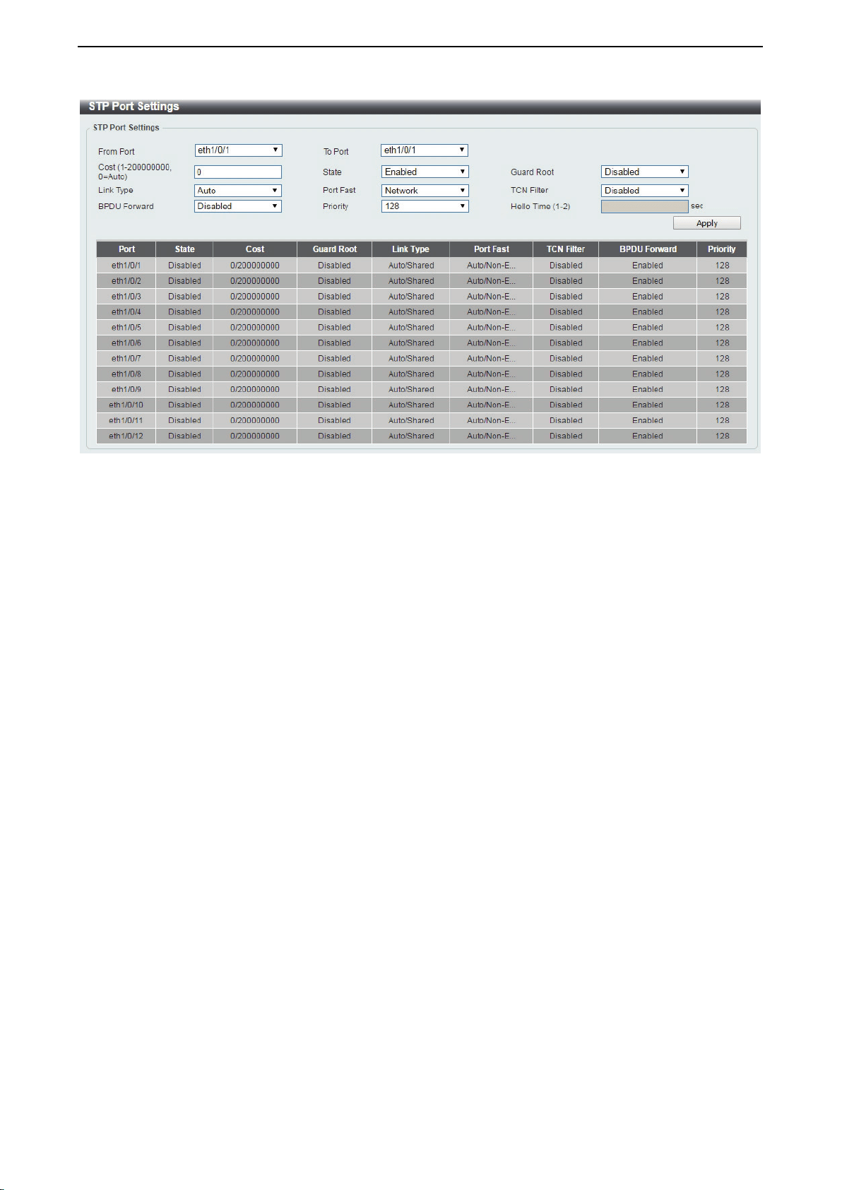
D-Link DXS-1210 Series User Manual
48
Figure 4.77 – L2 Features > STP > STP Port Settings
From Port/To Port: Enter a consecutive group of ports to be configured starting with the selected port.
Cost: This is the STP port cost, which is used to calculate the spanning tree topology. tf represents the
relative interface bandwidth and is the desirability of the link. The port cost can be set automatically or set
manually as a metric value. The default value is 0 (auto).
0 (auto): Setting 0 for the external cost will automatically set the speed for forwarding packets to the
specified port(s) in the list for optimal efficiency. Default port cost: 100Mbps port = 200000. Gigabit
port = 20000.
Value 1-200000000: Define a value between 1 and 200000000 to determine the external cost. The
lower the number, the greater the probability the port will be chosen to forward packets.
State: Select to enable or disable port based STP. It will be selectable after STP is enabled globally on the
Switch.
Guard Root: Select to enable or disable the guard root function.
Link Type: Select the link type option. The options to choose from are Auto, P2P, and Shared. A full-duplex
port is considered to have a point-to-point (P2P) connection. A half-duplex port is considered to have a
Shared connection. The port cannot rapidly transition to the forwarding state if the link type is set to Shared.
By default this option is Auto.
Port Fast: Select the port fast option. The options are Network, Disabled, and Edge. In the Network mode
the port will remain in the non-port, fast state for three seconds. If no BPDUs are received the port will be put
into the forwarding state. If the port receives a BPDU, it will change back to the non-port fast state. This is
the default port fast mode. In the Disabled mode, the port will always be in the non-port fast state. It will wait
for the forward-time delay to change to the forwarding state. In the Edge mode, the port will directly change
to the forwarding state without waiting for the forward-time delay. If the interface receives a BPDU, its
operation state changes to the non-port fast state.
TCN Filter: Select to enable or disable the TCN filter option. Enabling TCN filtering on a port is useful for
connecting to an external network, which may not be under full control of the administrator. When a port is
set to the TCN filter mode, the topology change event received by the port will be ignored. By default, this
option is disabled.
BPDU Forward: Bridges use Bridge Protocol Data Units (BPDUs) in the operation of spanning tree, BPDU.
Forwarding is useful when a bridge interconnects two regions, with each region requiring a separate
spanning tree. BPDU filtering functions only when STP is disabled either globally or on a single interface.
The possible field values are:
Disabled: BPDU filtering is enabled on the port.
Enabled: BPDU forwarding is enabled on the port (STP must be disabled).
Priority: Select the priority of each port. Selectable range is from 0 to 240, and the default setting is 128.
The lower the number, the greater the probability the port will be chosen as a root port.
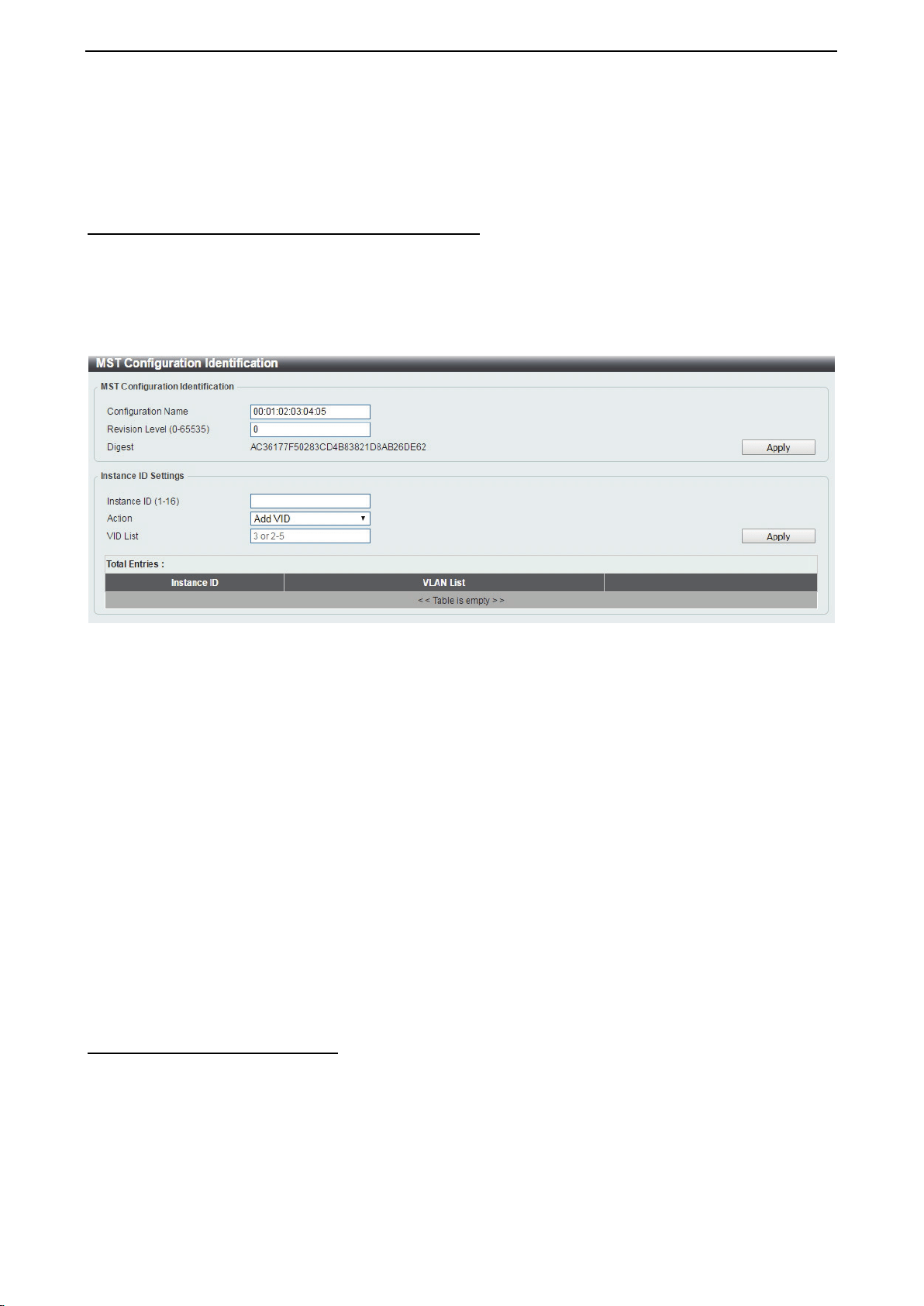
D-Link DXS-1210 Series User Manual
49
Hello Time: The interval between two transmissions of BPDU packets sent by the Root Bridge to indicate to
all other switches that it is indeed the Root Bridge. The default value is 2.
Click the Apply button to save your settings.
L2 Features > STP > MST Configuration Identification
Multiple Spanning Tree (MSTP) provides various load balancing scenarios by allowing multiple VLANs to be
mapped to a single spanning tree instance, providing multiple pathways across the network. For example,
while port A is blocked in one STP instance, the same port can be placed in the Forwarding state in another
STP instance.
The MST Configuration Identification page is for defining global MSTP settings, including region names,
MSTP revision level.
Figure 4.78 – L2 Features > STP > MST Configuration Identification
MST Configuration Identification:
Configuration Name: Enter a name set on the switch to uniquely identify the MSTI (multiple spanning tree
instance). If a configuration name is not set, this field shows the MAC address of the device running MSTP.
Revision Level(0 - 65535): This value, together with the configuration name and identical VLANs mapped
for STP instance IDs identifies the MST region configured on the switch.
Click Apply to define the configuration name and revision level.
Instance ID Settings:
Instance ID (1 - 64): Enter the MSTI ID associated with the VID List. The possible field range is 1-64.
Action: The possible values are:
Add VID - Indicates that the edit type is add.
Remove VID - Indicates that the edit type is removed.
VID List: Enter the VID range from configured VLANs set on the Switch.
Click the Apply button to save your settings.
Click the Edit to modify the setting of VID or click Delete to remove it.
L2 Features > STP > STP Instance
The STP Instance Settings page display MSTIs currently set on the Switch and allows users to change the
Priority of the MSTPs.

D-Link DXS-1210 Series User Manual
50
Figure 4.79 – L2 Features > STP > STP Instance
Click the Edit button to re-configure the specific entry.
L2 Features > STP > MSTP Port Information
The MSTP Port Information page allows you to configure the MSTP Interface settings.
Figure 4.80 – L2 Features > STP > MSTP Port Information
Port: Enter the port to find.
Click the Clear Detected Protocol button to clear the detected protocol settings for the port selected.
Click Find to search the MSTP port information.
Click the Edit button to re-configure the specific entry.
L2 Features > ERPS(G.8032) > ERPS
ERPS (Ethernet Ring Protection Switching) is the first industry standard (ITU-T G.8032) for Ethernet ring
protection switching. It is achieved by integrating mature Ethernet Operations, Administration, and
Maintenance (OAM)* functions and a simple automatic protection switching (APS) protocol for Ethernet ring
networks. ERPS provides sub-50ms failover for Ethernet traffic in a ring topology. It ensures that there are no
loops formed at the Ethernet layer.
One link within a ring, the ring Protection Link (RPL), will be blocked to avoid a Layer 2 loop. When there is a
failure, protection switching blocks the failed link and unblocks the RPL. When the failure clears, protection
switching blocks the RPL again and unblocks the link on which the failure is cleared.
The ERPS page allows you to configure the ERPS instance and profile configuration of the Switch.
Figure 4.81 – L2 Features > ERPS(G.8032) > ERPS
Instance ID (1-16): Specify the Instance ID to be created.
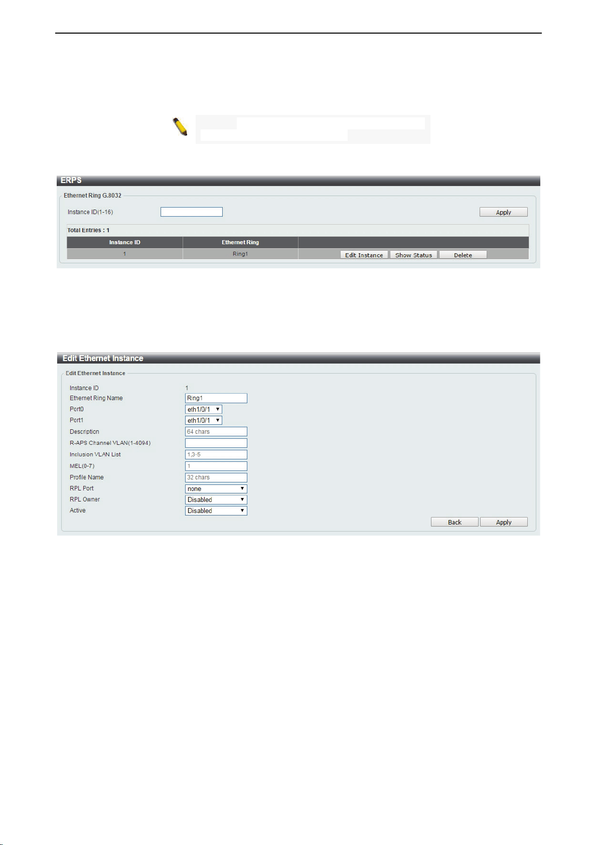
D-Link DXS-1210 Series User Manual
51
Click the Apply button to save your settings.
NOTE: STP and LBD should be disabled on the
ring ports before enabling ERPS.
Enter instance ID 1 and click Apply to create ERPS physical ring. Then the following page will be displayed.
Figure 4.82 – L2 Features > ERPS(G.8032) > ERPS - Create
Click Edit Instance button to modify the ERP instance, click Show Status button to display the ERPS
physical ring’s status information, or click Delete button to remove the Ethernet instance.
Click Edit Instance to modify the Ethernet Instance configuration:
Figure 4.83 – L2 Features > ERPS(G.8032) > ERPS – Edit Instance
Ethernet Ring Name: Enter the Ethernet ring name for the specified instance.
Sub Ring Name: Enter the sub ring name of a physical ring.
Port0: Specifies the port as the first ring port and also specifies the virtual port channel used.
Port1: Specifies the port as the second ring port and also specifies the virtual port channel used.
Description: Enter the description for the specified instance.
R-APS Channel VLAN (1-4094): Specifies the R-APS channel of ERP instance. The range is between 1
and 4094.
Inclusion VLAN List: Specifies to add or delete the inclusion VLAN group. The VLANs specified here will be
protected by the ERP mechanism.
MEL(0-7): Specifies the ring MEL of the R-APS function. The default ring MEL is 1.
Profile Name: Specifies the profile name of Ethernet Instance.
RPL Port: Specifies the RPL port used. Options to choose from are Port0, Port1, and None.
RPL Owner: Specifies to enable or disable the RPL owner node.
Active: Specifies enable or disable to active this ERP instance.
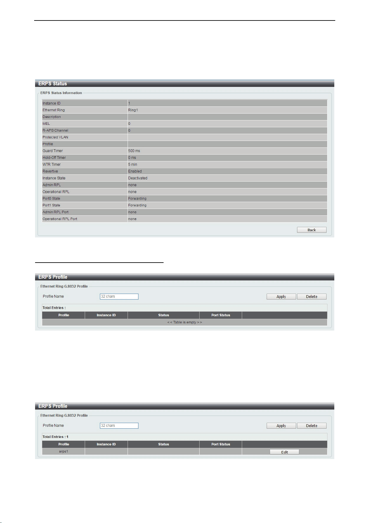
D-Link DXS-1210 Series User Manual
52
Click the Apply button to save your settings.
Click the Back button to return to the previous page.
Click Show Status button to display the ERPS status information.
Figure 4.84 – L2 Features > ERPS(G.8032) > ERPS – Show Status
L2 Features > ERPS(G.8032) > ERPS Profile
The ERPS Profile page allows you to configure the ERPS profile information of the Switch.
Figure 4.85 – L2 Features > ERPS(G.8032) > ERPS Profile
Profile Name: Specify the profile name to be created on the Switch.
Click the Apply button to save your settings.
Click the Delete button to remove the profile.
Enter Profile Name and click Apply button to associate the G.8032 profile with the ERP instance created.
Figure 4.86 – L2 Features > ERPS(G.8032) > ERPS Profile - created
Click Edit button to configure the Ethernet Profile settings:
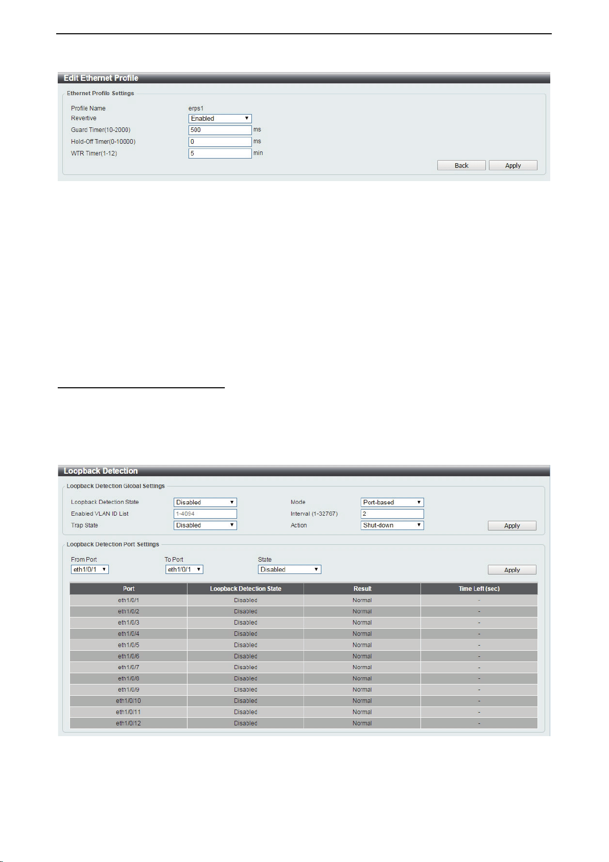
D-Link DXS-1210 Series User Manual
53
Figure 4.87 – L2 Features > ERPS(G.8032) > ERPS Profile - Edit
Revertive: Specifies whether to enable or disable to the original state after a failure, for example, when the
RPL was blocked.
Guard Time (10-2000): Specifies the guard time of the R-APS function. The value is between 10 and 2000
milliseconds. The default guard time is 500 milliseconds.
Hold-Off Timer (0-10000): Specifies the hold-off time of the R-APS function. The value is between 0 and
10000 milliseconds. The default hold-off time is 0 milliseconds.
WTR Timer (1-12): Specifies the WTR time of the R-APS function. The value is between 1 and 12 minutes.
The default WTR time is 5 minutes.
Click the Apply button to save your settings.
Click the Back button to return to the previous page.
L2 Features > Loopback Detection
The Loopback Detection function is used to detect the loop created by a specific port while Spanning Tree
Protocol (STP) is not enabled in the network, especially when the down links are hubs or unmanaged
switches. The Switch will automatically shut down the port and send a log to the administrator. The Loopback
Detection port will be unlocked when the Loopback Detection Recover Time times out. The Loopback
Detection function can be implemented on a range of ports at a time. You may enable or disable this function
using the pull-down menu.
Figure 4.88 – L2 Features > Loopback Detection Settings
Loopback Detection State: Enable or disable loopback detection. The default is disabled.
Mode: Select either Port-based or VLAN-based loopback detection.
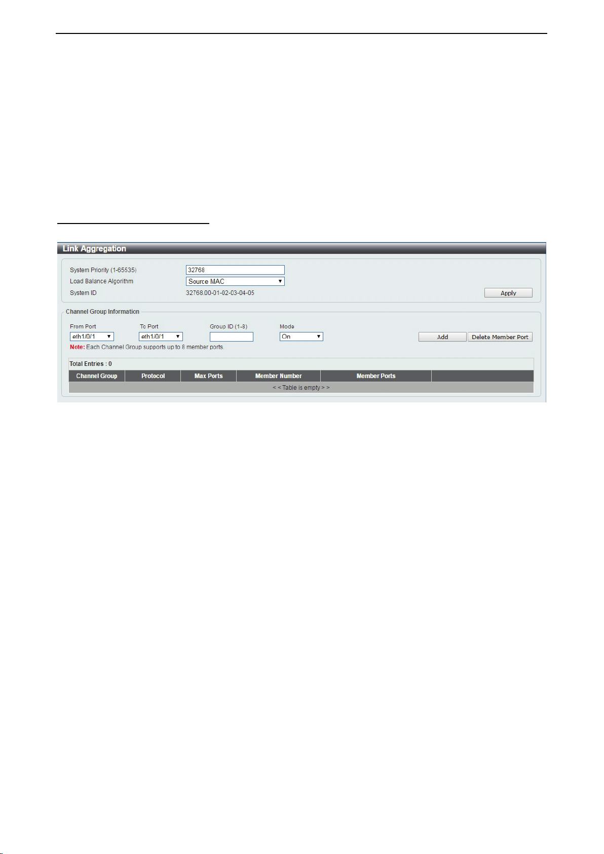
D-Link DXS-1210 Series User Manual
54
Enabled VLAN ID List: Enter the VLAN ID for loopback detection. This only takes effect when VLAN-based
is selected in the Mode drop-down list.
Interval (1-32767): Set a Loop Detection Interval between 1 and 32767 seconds. The default is 2 seconds.
Trap State: Select to enable or disable the loopback detection trap state.
Action: Select Shut-down or None for loopback detection.
From Port / To Port: Enter a consecutive group of ports to be configured starting with the selected port.
State: Use the drop-down menu to toggle between Enabled and Disabled. Default is disabled.
Click the Apply button to save your settings.
L2 Features > Link Aggregation
The Link Aggregation page allows you to view and configure the link aggregation settings.
Figure 4.89 – L2 Features > Link Aggregation
System Priority (1-65535): Enter the system’s priority value. This must be between 1 and 65535. By default,
the value is 32768. The system priority determines which ports can join a port-channel and which ports are
put in stand-alone mode. The lower value has a higher priority. If two or more ports have the same priority,
the port number determines the priority.
Load Balance Algorithm: Specify the load balancing algorithm that will be used. Options to choose from
are: Source MAC, Destination MAC, Source Destination MAC, Source IP, Destination IP, and Source
Destination IP. By default, this option is Source MAC.
System ID: The System ID information.
Click the Apply button to save your settings.
Channel Group Information:
From Port / To Port: Select the appropriate port range used for the configuration.
Group ID: Enter the channel-group number. This value must be between 1 and 32. The system will
automatically create the port-channel when a physical port first joins a channel-group. An interface can only
join one channel-group.
Mode: Select either On, Active, or Passive. If you selected On, the channel-group type is static. If Active or
Passive is selected, the channel-group type is LACP. A channel-group can only consist of either static
members or LACP members. Once the type of channel-group has been determined, other types of interfaces
cannot join the channel-group.
Click the Add button to add a new entry based on the information entered.
Click the Delete Member Port button to remove the specific member port.
Click the Delete Channel button to remove the specific entry.
Click the Channel Detail button to view more detailed information about the channel.
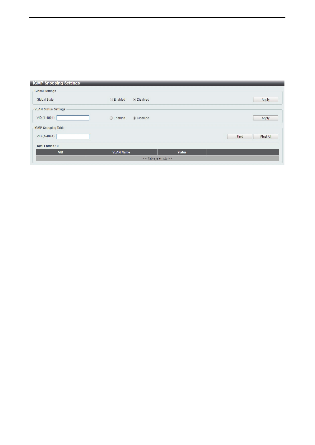
D-Link DXS-1210 Series User Manual
55
L2 Features > L2 Multicast Control > IGMP Snooping > IGMP Snooping Settings
With Internet Group Management Protocol (IGMP) snooping, the DXS-1210 Series Switch can make
intelligent multicast forwarding decisions by examining the contents of each frame’s Layer 2 MAC header.
IGMP snooping can help reduce cluttered traffic on the LAN. With IGMP snooping enabled globally, the
DXS-1210 Series Switch will forward multicast traffic only to connections that have group members attached.
The settings of IGMP snooping is set by each VLAN individually.
Figure 4.90 – L2 Features > L2 Multicast Control > IGMP Snooping > IGMP Snooping Settings
Global Settings:
Global State: Select to enable or disable the IGMP Snooping global state.
Click the Apply button to save your settings.
VLAN Status Settings:
VID (1-4094): Enter the VLAN ID and select to enable or disable the IGMP snooping on the VLAN.
Click the Apply button to save your settings.
IGMP Snooping Table:
VID (1-4094): Enter the VLAN ID between 1 and 4094.
Click the Find button to display a specific entry based on the information entered.
Click the Find All button to display all the entries.
Click the Show Detail button to display the detail information of the specified VLAN.
Click the Edit button to re-configure the specific entry.
Enter a page number and click the Go button to navigate to a specific page when multiple pages exist.
After clicking the Show Detail button, the following window will appear:
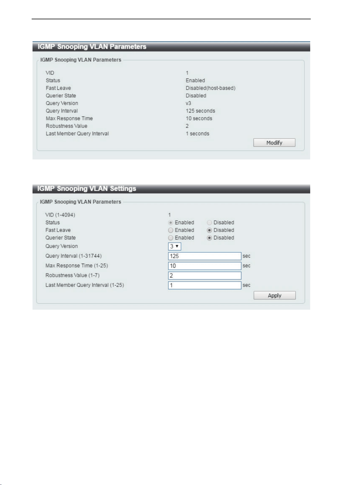
D-Link DXS-1210 Series User Manual
56
Figure 4.91 – L2 Features > L2 Multicast Control > IGMP Snooping > IGMP Snooping – Show Detail
Click the Modify button to edit the information in the following window:
Figure 4.92 L2 Features > L2 Multicast Control > IGMP Snooping > IGMP Snooping – Modify
The following parameters can be configured:
Fast Leave: Select to enable or disable the IGMP snooping fast leave function.
Querier State: Select to enable or disable the querier state.
Query Version: Select the general query packet version sent by the IGMP snooping querier.
Query Interval (1-31744): Enter the interval at which the IGMP snooping querier sends IGMP general query
messages periodically.
Max. Response Time (1-25): Enter the maximum response time. The range is between 1 and 25 seconds.
Robustness Value (1-7): Enter the robustness variable used in IGMP snooping.
Last Member Query Interval (1-25): Enter the interval at which the IGMP snooping querier sends IGMP
group-specific or group-source-specific query messages.
Click the Apply button to save your settings.
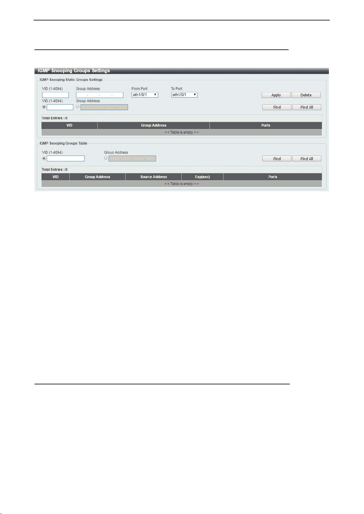
D-Link DXS-1210 Series User Manual
57
L2 Features > L2 Multicast Control > IGMP Snooping > IGMP Snooping Groups Settings
The IGMP snooping Groups Settings page allows you to configure and view the IGMP snooping static group,
and view IGMP snooping group.
Figure 4.93 – L2 Features > L2 Multicast Control > IGMP Snooping > IGMP Snooping Group Settings
VID (1-4094): Enter the VLAN ID.
Group Address: Enter the IP multicast group address.
From Port / To Port: Select the range of ports to be configured.
Click the Apply button to save your settings.
Click the Delete button to remove the specified entry.
Click the Find button to locate a specific entry based on the information entered.
Click the Find All button to view all the entries.
Enter a page number and click the Go button to navigate to a specific page when multiple pages exist.
The fields that can be configured for IGMP Snooping Groups Table are described below:
IGMP Snooping Group Table:
VID (1-4094): Specify the VLAN ID.
Group Address: Click the radio button and enter an IP multicast group address.
Click the Find button to locate a specific entry based on the information entered.
Click the Find All button to view all the entries.
L2 Features > L2 Multicast Control > IGMP Snooping > IGMP Snooping Mrouter Settings
The IGMP Snooping Mrouter Settings page allows you to configure interfaces as multicast router ports or
ports that cannot be multicast router ports on the Switch.
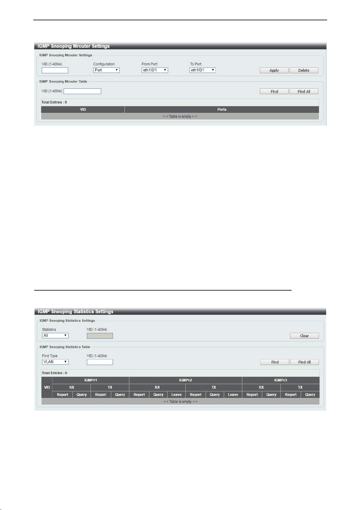
D-Link DXS-1210 Series User Manual
58
Figure 4.94 – L2 Features > L2 Multicast Control > IGMP Snooping > IGMP Snooping Mrouter Settings
VID (1-4094): Enter the VLAN ID in the range 1 to 4094.
Configuration: Select the port configuration type.
Port: Select to configure the port as a static multicast router port.
Forbidden Port: Select to configure the port as a port that cannot be a static multicast router port.
From Port / To Port: Select the range of ports to be configured.
Click the Apply button to save your settings.
Click the Delete button to remove the specified entry.
The IGMP Snooping Mrouter Table is showed as below:
VID (1-4094): Enter the VLAN ID to be searched.
Click the Find button to locate a specific entry based on the information entered.
Click the Find All button to view all the entries.
Enter a page number and click the Go button to navigate to a specific page when multiple pages exist.
L2 Features > L2 Multicast Control > IGMP Snooping > IGMP Snooping Statistics Settings
The IGMP Snooping Statistics Settings page allows you to clear and display the IGMP snooping related
statistics.
Figure 4.95 – L2 Features > L2 Multicast Control > IGMP Snooping > IGMP Snooping Statistics Settings
Statistics: Select the interface to be cleared. The options are All and VLAN.
VID (1-4094): Enter the VLAN ID.
Click the Clear button to clear the IGMP snooping related statistics.
The fields that can be configured for IGMP Snooping Statistics Table are listed below:
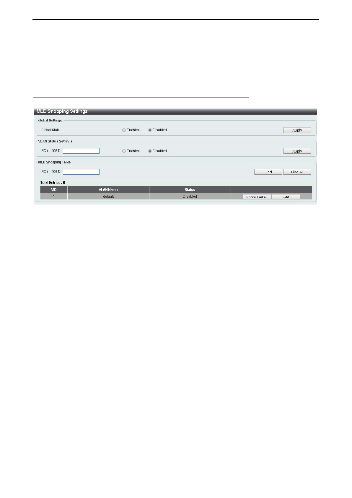
D-Link DXS-1210 Series User Manual
59
Find Type: Select the interface to be searched. The options are VLAN and Port.
VID (1-4094): Enter the VLAN ID.
Click the Find button to locate a specific entry based on the information entered.
Click the Find All button to view all the entries.
L2 Features > L2 Multicast Control > MLD Snooping > MLD Snooping Setting
The MLD Snooping Settings page allows you to configure the MLD snooping settings.
Figure 4.96 – L2 Features > L2 Multicast Control > MLD Snooping > MLD Snooping Setting
Global Settings:
Global State: Select to enable or disable the MLD Snooping state.
Click the Apply button to save your settings.
VLAN Status Settings:
VID (1-4094): Enter the VLAN ID and select to enable or disable MLD snooping on the VLAN.
Click the Apply button to save your settings.
MLD Snooping Table:
VID (1-4094): Enter the VLAN ID to be searched.
Click the Find button to locate a specific entry based on the information entered.
Click the Find All button to view all the entries.
Click the Show Detail button to see the detail information of the specific VLAN.
Click the Edit button to re-configure the specific entry.
After clicking the Show Detail button, the following window will appear.
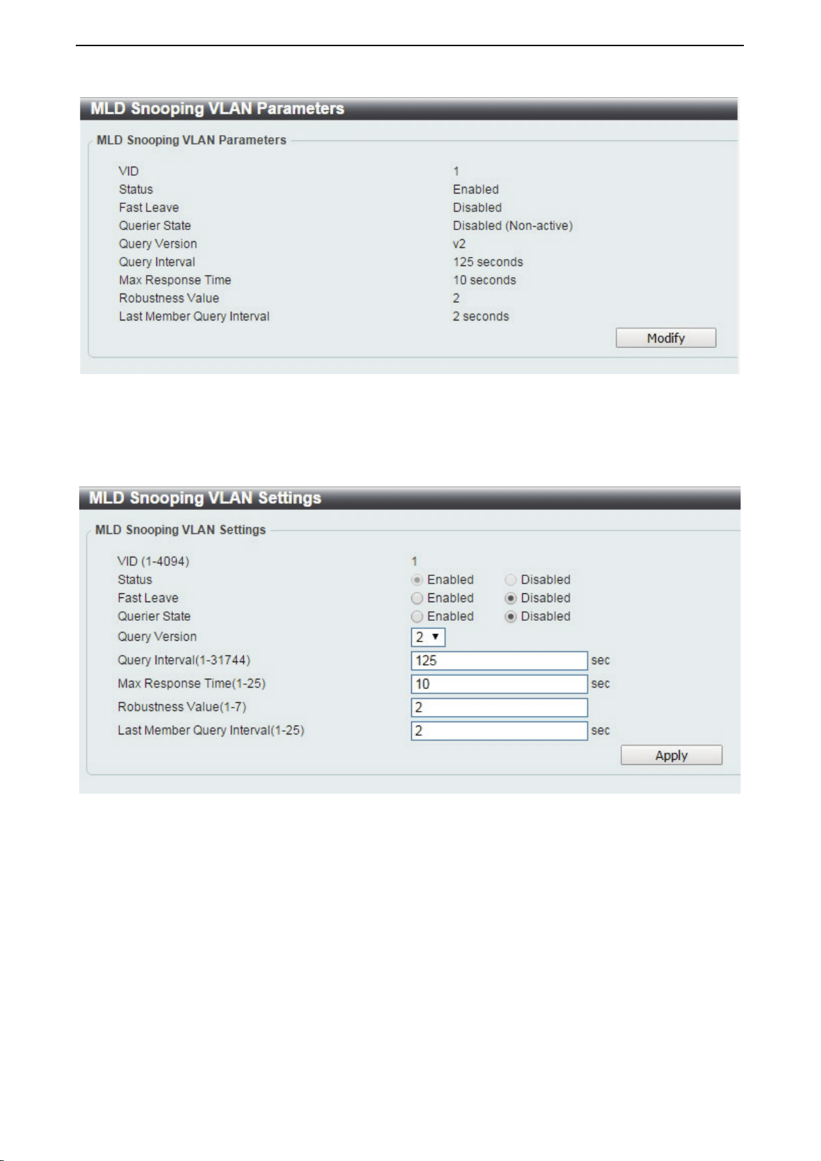
D-Link DXS-1210 Series User Manual
60
Figure 4.97 – L2 Features > L2 Multicast Control > MLD Snooping > MLD Snooping Setting – Show Detail
The window displays the detail information about MLD snooping VLAN. Click the Modify button to edit the
information in the following window.
After clicking the Edit button in MLD Snooping Settings window, the following window will appear.
Figure 4.98 – L2 Features > L2 Multicast Control > MLD Snooping > MLD Snooping Setting – Edit
Fast Leave: Select to enable or disable the MLD snooping fast leave function.
Querier State: Select to enable or disable the querier state.
Query Version: Select the general query packet version sent by the MLD snooping querier.
Query Interval (1-31744): Enter the interval at which the MLD snooping querier sends MLD general query
messages periodically.
Max. Response Time (1-25): Enter the maximum response time, in seconds, advertised in MLD snooping
queries. The range is 1 to 25.
Robustness Value (1-7): Enter the robustness variable used in MLD snooping.
Last Member Query Interval (1-25): Enter the interval at which the MLD snooping querier sends MLD
group-specific or group-source-specific (channel) query messages.
Click the Apply button to save your settings.
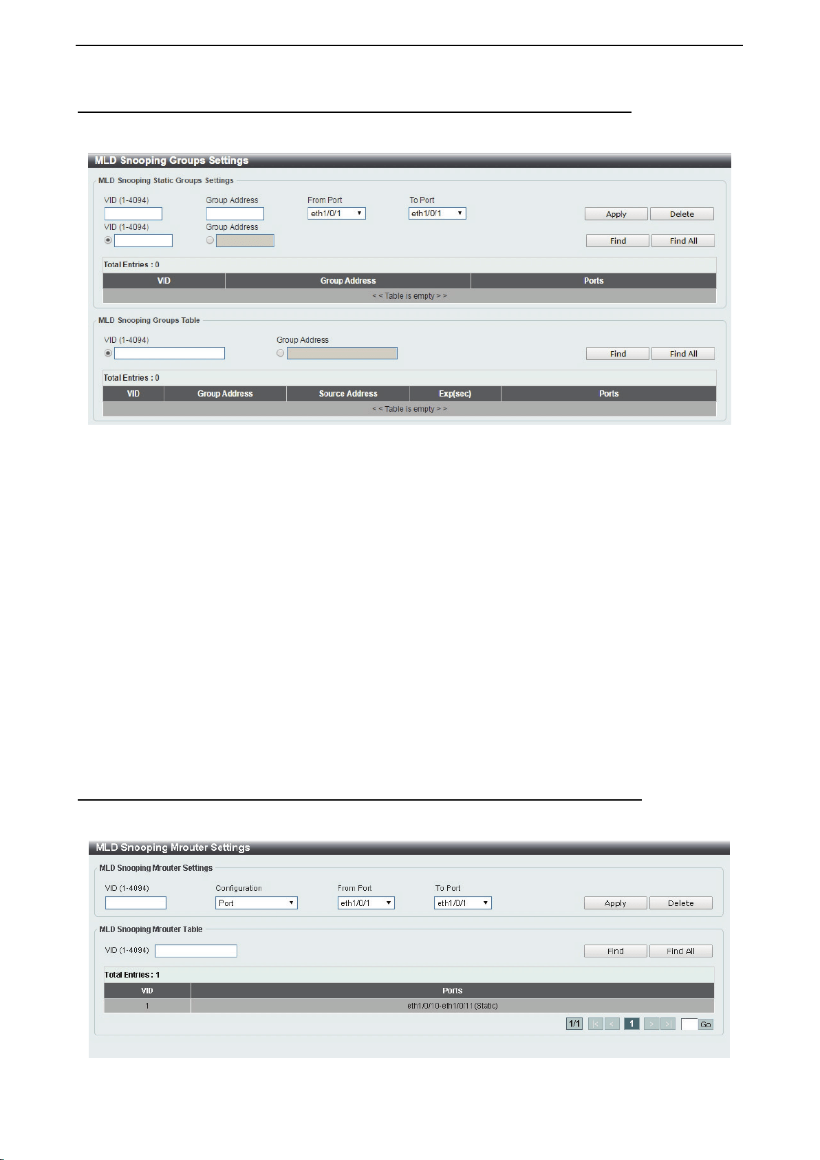
D-Link DXS-1210 Series User Manual
61
L2 Features > L2 Multicast Control > MLD Snooping > MLD Snooping Groups Setting
The MLD Snooping Groups Settings page allows you to configure and view the MLD snooping static group,
and view MLD snooping group.
Figure 4.99 – L2 Features > L2 Multicast Control > MLD Snooping > MLD Snooping Group Setting
VID (1-4094): Enter the VLAN ID.
Group Address: Enter the IP multicast group address.
From Port / To Port: Select the range of ports to be configured.
Click the Apply button to save your settings.
Click the Delete button to remove the specified entry.
Click the Find button to locate a specific entry based on the information entered.
Click the Find All button to view all the entries.
Enter a page number and click the Go button to navigate to a specific page when multiple pages exist.
The fields that can be configured for the MLD Snooping Groups Table are described below:
VID (1-4094): Enter the VLAN ID.
Group Address: Enter the IP multicast group address.
Click the Find Snooping button to locate a specific entry based on the information entered.
Click the Find All Snooping button to view all the entries.
L2 Features > L2 Multicast Control > MLD Snooping > MLD Snooping Mrouter Settings
The MLD Snooping Mrouter Settings page allows you to configure the interfaces as router ports or ports that
cannot be multicast router ports on the Switch.
Figure 4.100 – L2 Features > L2 Multicast Control > MLD Snooping > MLD Snooping Mrouter Settings
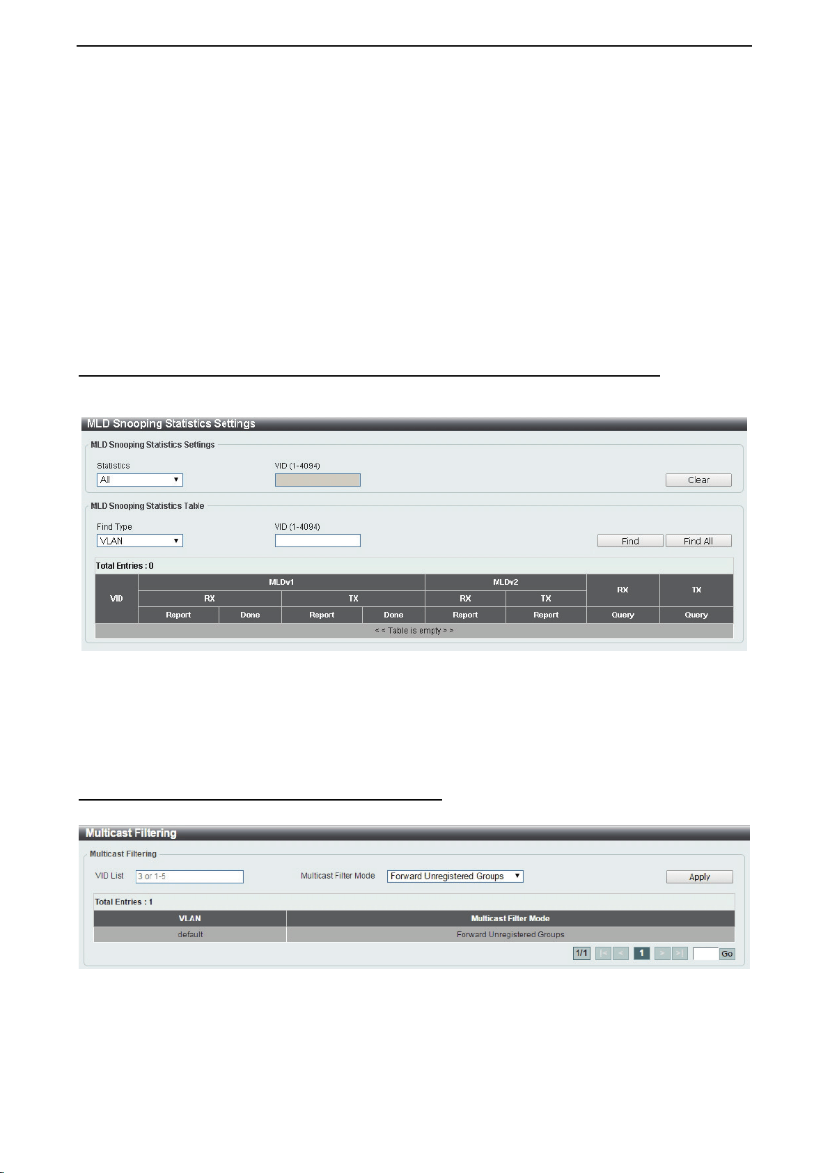
D-Link DXS-1210 Series User Manual
62
VID (1-4094): Enter the VLAN ID.
Configuration: Select the port configuration type.
Port: Select to configure the port as being connected to a multicast-enabled router.
Forbidden Port: Select to configure the port as not being connected to a multicast-enabled router.
From Port / To Port: Select the range of ports to be configured.
Click the Apply button to save your settings.
Click the Delete button to remove the specified entry.
Click the Find button to locate a specific entry based on the information entered.
Click the Find All button to view all the entries.
Enter a page number and click the Go button to navigate to a specific page when multiple pages exist.
L2 Features > L2 Multicast Control > MLD Snooping > MLD Snooping Statistics Settings
The MLD Snooping Statistics Settings page allows you to clear and display the MLD snooping related
statistics.
Figure 4.101 – L2 Features > L2 Multicast Control > MLD Snooping > MLD Snooping Statistics Settings
Statistics: Select the type of statistics to display. Available options are All and VLAN.
VID (1-4094): Enter the VLAN ID.
Click the Find button to locate a specific entry based on the information entered.
Click the Find All button to view all the entries.
L2 Features > L2 Multicast Control > Multicast Filtering
The Multicast Filtering page allows you to view and configure multicast filtering settings.
Figure 4.102 – L2 Features > L2 Multicast Control > Multicast Filtering
VID List: Enter the VLAN ID.
Multicast Filter Mode: Select the multicast filter mode. Options to choose from are Forward Unregistered,
Forward All, and Filter Unregistered. When selecting the Forward Unregistered option, registered
multicast packets will be forwarded based on the forwarding table and all unregistered multicast packets will
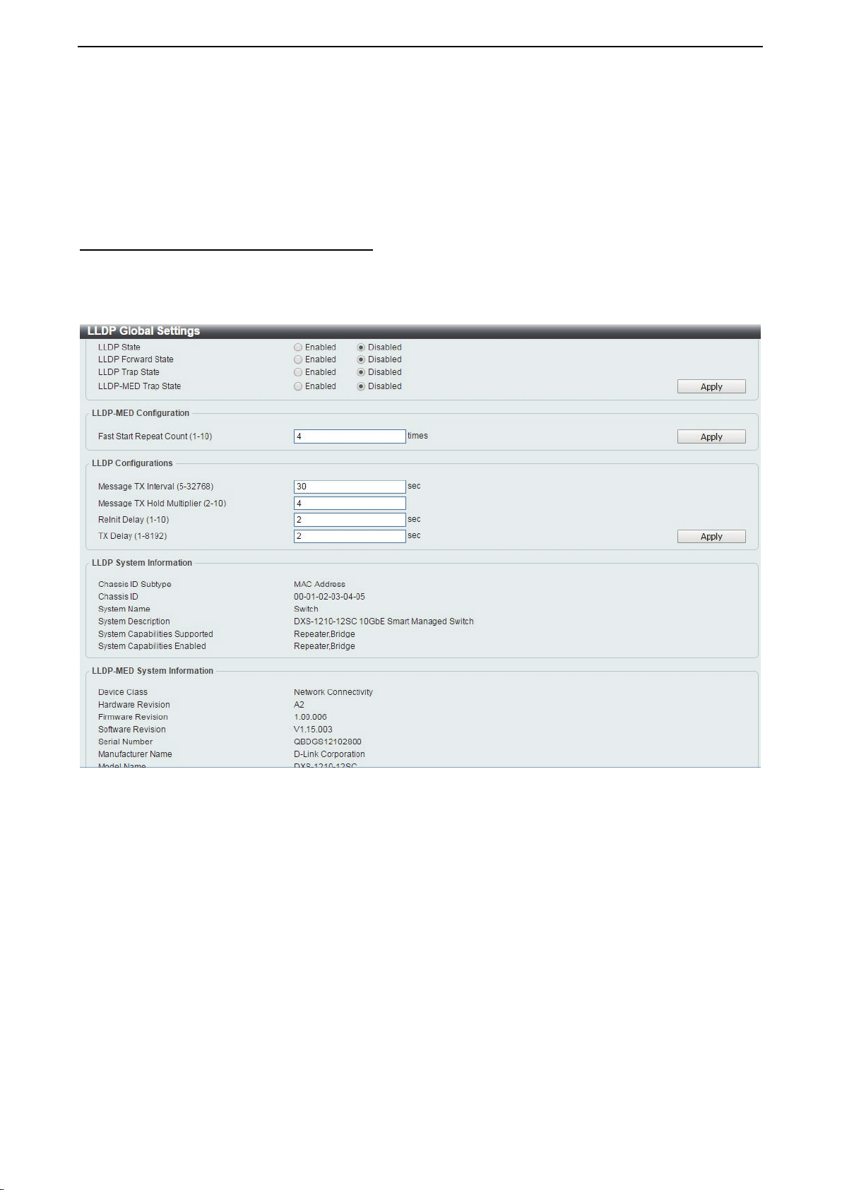
D-Link DXS-1210 Series User Manual
63
be flooded based on the VLAN domain. When selecting the Forward All option, all multicast packets will be
flooded based on the VLAN domain. When selecting the Filter Unregistered option, registered packets will
be forwarded based on the forwarding table and all unregistered multicast packets will be filtered.
Click the Apply button to save your settings.
Enter a page number and click the Go button to navigate to a specific page when multiple pages exist.
L2 Features > LLDP > LLDP Global Settings
Link Layer Discovery Protocol (LLDP) is and IEEE 802.1AB standards-compliant method for switches to
advertise themselves to neighbor devices, as well as to learn about neighbor LLDP devices. SNMP utilities
can learn the network topology by obtaining the MIB information for each LLDP device. The LLDP function is
enabled by default.
Figure 4.103 – L2 Features > LLDP > LLDP Global Settings
LLDP Global Settings:
LLDP State: Select to enable or disable LLDP globally on the Switch. With this enabled, the Switch will
transmit receive and process LLDP packets.
LLDP Forward State: Select to enable or disable LLDP forward state. When the LLDP State is disabled and
LLDP Forward Sate is enabled, the received LLDPDU packet will be forwarded.
LLDP Trap State: Select to enable or disable the LLDP trap state.
LLDP-MED Trap State: Select to enable or disable the LLDP-MED trap state.
Click the Apply button to save your settings.
LLDP-MED Configuration:
Fast Start Repeat Count (1-10): Enter the LLDP-MED fast start repeat count value. This value must be
between 1 and 10.
Click the Apply button to save your settings.
LLDP Configurations:
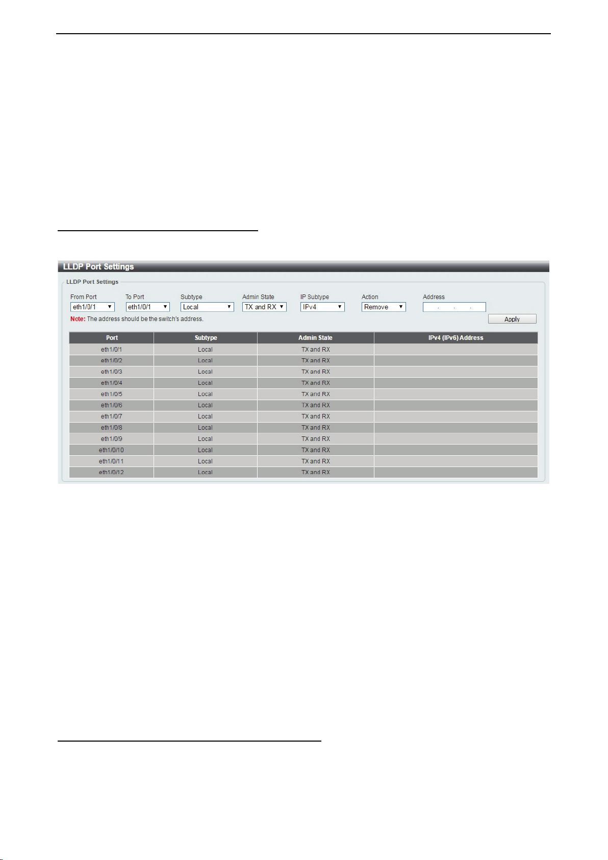
D-Link DXS-1210 Series User Manual
64
Message TX Interval (5-32768): This parameter indicates the interval at which LLDP frames are transmitted
on behalf of this LLDP agent. The default value is 30 seconds.
Message TX Hold Multiplier (2-10): This parameter is a multiplier that determines the actual TTL value
used in an LLDPDU. The default value is 4.
LLDP ReInit Delay (1-10): This parameter indicates the amount of delay from the time adminStatus
becomes disabled until re-initialization is attempted. The default value is 2 seconds.
LLDP TX Delay (1-8192): This parameter indicates the delay between successive LLDP frame
transmissions initiated by value or status changes in the LLDP local systems MIB. The value for txDelay is
set by the following range formula: 1 < txDelay < (0.25 °— msgTxInterval). The default value is 2 seconds.
Click the Apply button to save your settings.
L2 Features > LLDP > LLDP Port Settings
The Basic LLDP Port Settings page displays LLDP port information and contains parameters for configuring
LLDP port settings.
Figure 4.104 – L2 Features> LLDP > LLDP Port Settings
From Port/ To Port: Select the range of ports to be configured.
Subtype: Select the subtype of LLDP Type Length Value (TLV). Options to choose from are MAC Address,
and Local.
Admin Status: Select the LLDP transmission mode on the port. The available options are:
TX: Enables transmitting LLDP packets only.
RX: Enables receiving LLDP packets only.
TX and RX: Enables transmitting and receiving LLDP packets. This is the default value.
Disabled: Disables LLDP on the port.
IP Subtype: Select the type of the IP address information to be sent. Options to choose from are All, IPv4
and IPv6.
Action: Select to remove or add the action field.
Address: Enter the IP address to be sent.
Click Apply to accept the changes made.
L2 Features > LLDP > LLDP Management Address List
The LLDP Management Address List page displays the detailed management address information for the
entry.
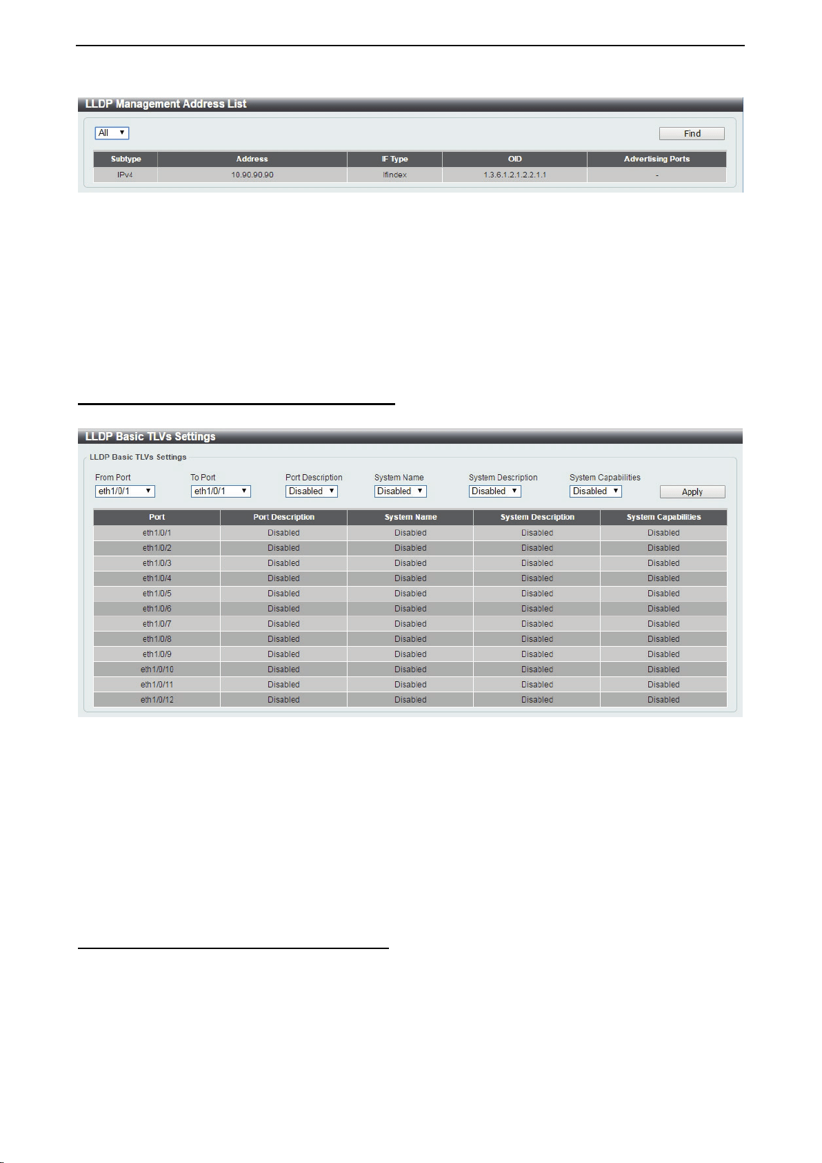
D-Link DXS-1210 Series User Manual
65
Figure 4.105 – L2 Features > LLDP >LLDP Management Address List
Management Address: Select IPv4, IPv6 or All address to be displayed. Click Find and the table will update
and display the values required.
Subtype: Displays the managed address subtype (e.g. MAC or IPv4)
Address: Displays the IP address.
IF Type: Displays the IF Type.
OID: Displays the SNMP OID.
Advertising Ports: Displays the advertising ports.
L2 Features > LLDP > LLDP Basic TLVs Settings
This LLDP Basic TLVs Settings page allows you to configure the LLDP Port settings.
Figure 4.106 – L2 Features > LLDP > LLDP Basic TLVs Settings
From Port / To Port: Select the range of ports to be configured.
Port Description: Select to enable or disable the Port Description option.
System Name: Select the system name to be enabled or disabled in the LLDP port. If enabled is selected,
users can specify the content of the system Name.
System Description: Select to enable or disable the System Description option.
System Capabilities: Select to enable or disable the System Capabilities option.
Click Apply to accept the changes made.
L2 Features > LLDP > LLDP Dot1 TLVs Settings
This LLDP Dot1 TLVs Settings page allows you to configure an individual port or group of ports to exclude
one or more of the IEEE 802.1 organizational port VLAN ID TLV data types from outbound LLDP
advertisements.
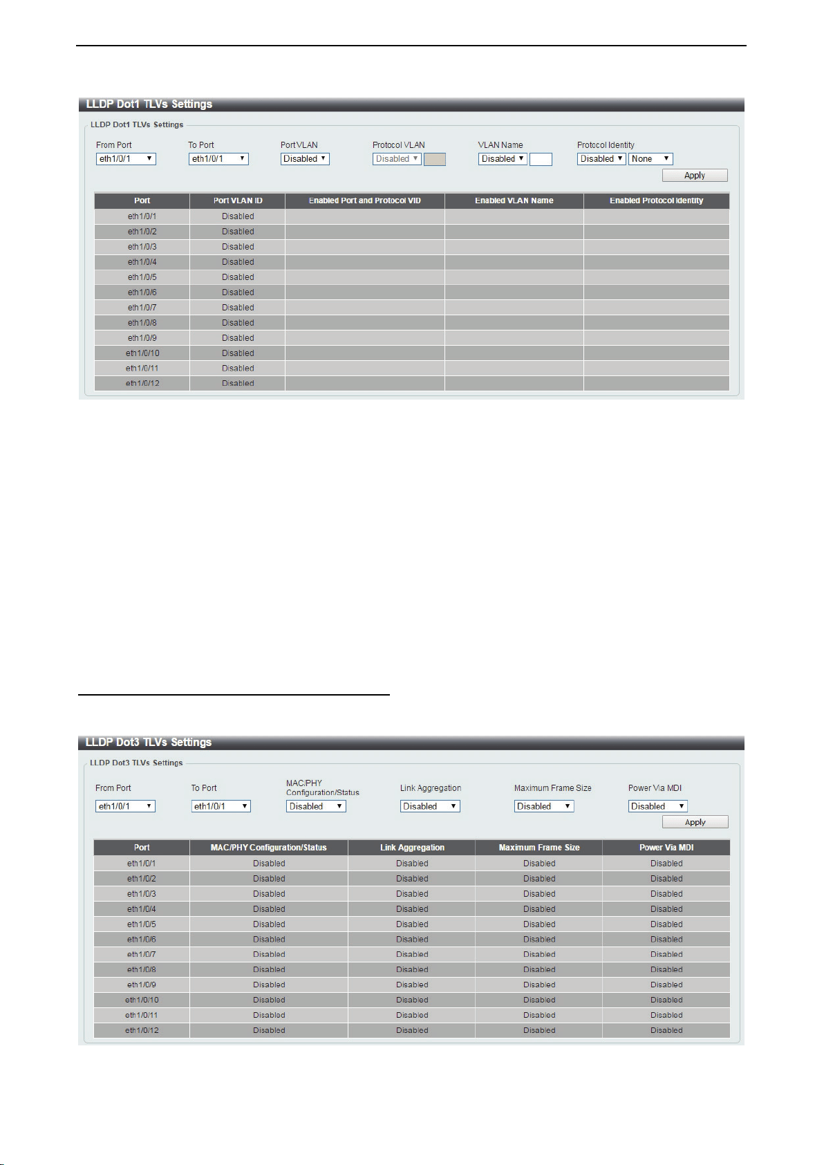
D-Link DXS-1210 Series User Manual
66
Figure 4.107 – L2 Features > LLDP > LLDP Dot1 TLVs Settings
From Port / To Port: Select the range of ports to be configured.
Port VLAN: Select to enable or disable the port VLAN ID TLV to send. The Port VLAN ID TLV is an optional
fixed length TLV that allows a VLAN bridge port to advertise the port’s VLAN identifier (PVID) that will be
associated with untagged or priority tagged frames.
Protocol VLAN: Select to enable or disable Port and Protocol VLAN ID (PPVID) TLV to send, and enter the
VLAN ID in PPVID TLV.
VLAN Name: Select to enable or disable the VLAN name TLV to send, and enter the ID of the VLAN in the
VLAN name TLV.
Protocol Identity: Select to enable or disable the Protocol Identity TLV to send, and the protocol name.
Options for protocol name to choose from are None, EAPOL, LACP, GVRP, STP, and All.
Click the Apply button to save your settings.
L2 Features > LLDP > LLDP Dot3 TLVs Settings
The LLDP Dot3 TLVs Settings page allows you to configure an individual port or group of ports to exclude
one or more IEEE 802.3 organizational specific TLV data type from outbound LLDP advertisements.
Figure 4.108 – L2 Features > LLDP > LLDP Dot3 TLVs Settings
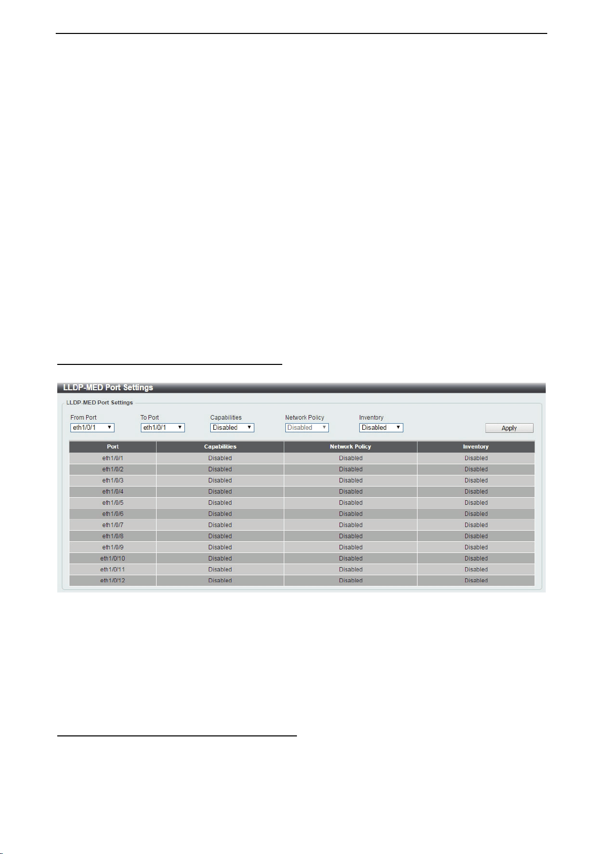
D-Link DXS-1210 Series User Manual
67
From Port/To Port: A consecutive group of ports may be configured starting with the selected port.
MAC/PHY Configuration/Status: Select whether the MAC/PHY Configuration Status is enabled on the port.
The possible field values are:
Enabled: Enables the MAC/PHY Configuration Status on the port.
Disabled: Disables the MAC/PHY Configuration Status on the port.
Link Aggregation: Specifies whether the link aggregation is enabled on the port. The possible field values
are:
Enabled: Enables the link aggregation configured on the port.
Disabled: Disables the link aggregation configured on the port.
Maximum Frame Size: Specifies whether the Maximum Frame Size is enabled on the port. The possible
field values are:
Enabled: Enables the Maximum Frame Size configured on the port.
Disabled: Disables the Maximum Frame Size configured on the port.
Power via MDI: Advertises the Power via MDI implementations supported by the port. The possible field
values are:
Enabled: Enables the Power via MDI configured on the port.
Disabled: Disables the Power via MDI configured on the port.
Click Apply to implement changes made.
L2 Features > LLDP > LLDP-MED Port Settings
The LLDP-MED Port Settings page allows you to enable or disable transmitting LLDP-MED TLVs.
Figure 4.109 – L2 Features > LLDP > LLDP-MED Port Settings
From Port/To Port: Select the range of ports to be configured.
Capabilities: Select to enable or disable transmitting the LLDP-MED capabilities TLV.
Network Policy: Select to enable or disable transmitting the LLDP-MED network policy TLV.
Inventory: Select to enable or disable transmitting the LLDP-MED inventory management TLV.
Click Apply to accept the changes made.
L2 Features > LLDP > LLDP Statistics Information
The LLDP Statistics Information page displays an overview of the LLDP information.
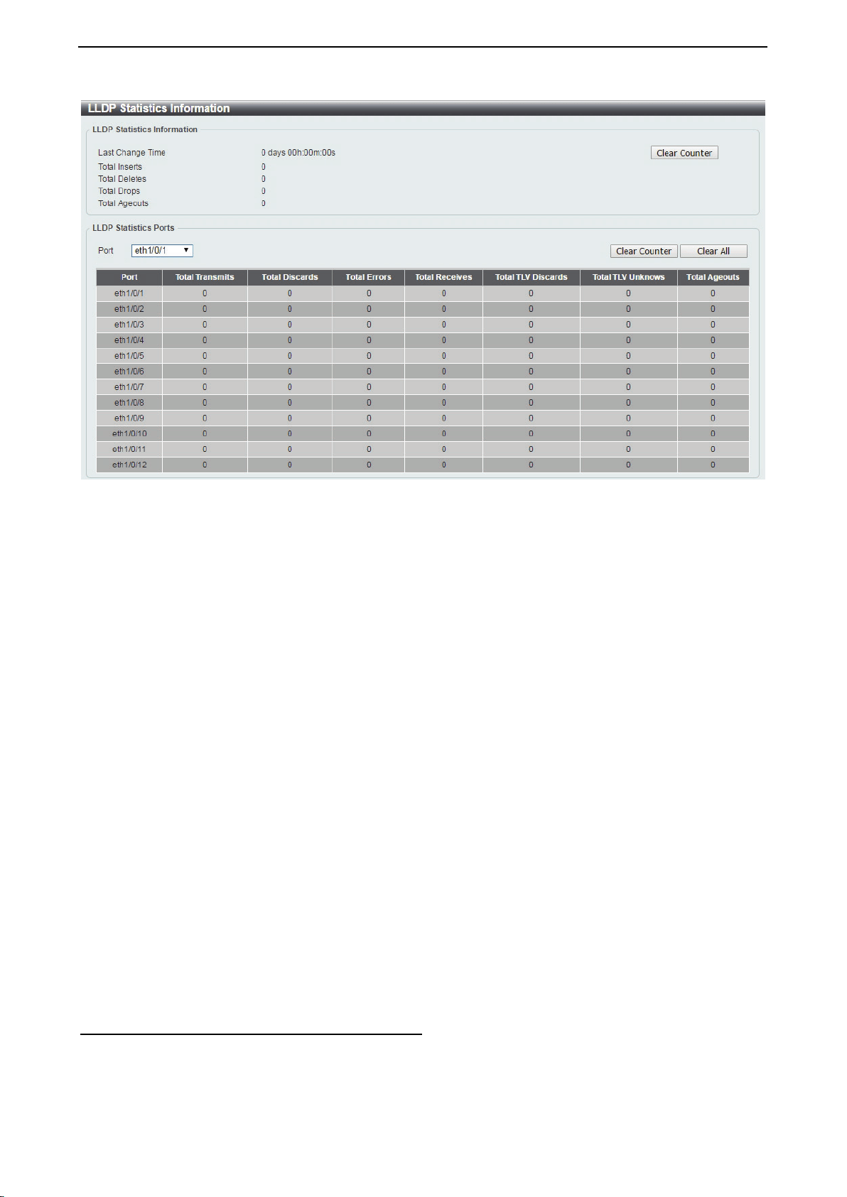
D-Link DXS-1210 Series User Manual
68
Figure 4.110 – L2 Features > LLDP > LLDP Statistics Information
The following statistics can be viewed:
LLDP Statistics Information: Displays the counters that refer to the whole switch.
Last Change Time: Displays the time of the last change. It also displays the amount of time that has
elapsed since the change was detected.
Total Inserts: Displays the number of new entries, since the last switch reboot.
Total Deletes: Displays the number of new entries, since the last switch reboot.
Total Drops: Displays the number of LLDP frames dropped due to the table was full.
Total Ageouts: Displays the number of entries deleted due to the Time-To-Live expiring.
LLDP Statistics Ports: Displays LLDP port statistics.
Port: Select the port to be displayed.
Total Transmits: Displays the total number of LLDP frames transmitted on the port.
Total Discards: Displays the total discarded frame number of LLDP frames received on the port.
Total Errors: Displays the Error frame number of LLDP frames received on the port.
Total Receives: Displays the total number of LLDP frames received on the port.
Total TLV Discards: Each LLDP frame can contain multiple pieces of information, known as TLVs.
If a TLV is malformed, it is counted and discarded.
Total TLV Unknowns: Displays the number of well-formed TLVs, but with a known type value.
Total Ageouts: Each LLDP frame contains information about how long time the LLDP information is
valid. If no new LLDP frame is received within the age out time, the LLDP information is removed,
and the Age-Out counter is incremented.
Click the Clear Counter button to clear the counter information for the statistics displayed.
Click the Clear All button to clear all the counter information displayed.
L2 Features > LLDP > LLDP Local Port Information
The LLDP Local Port Information page displays LLDP local port information.
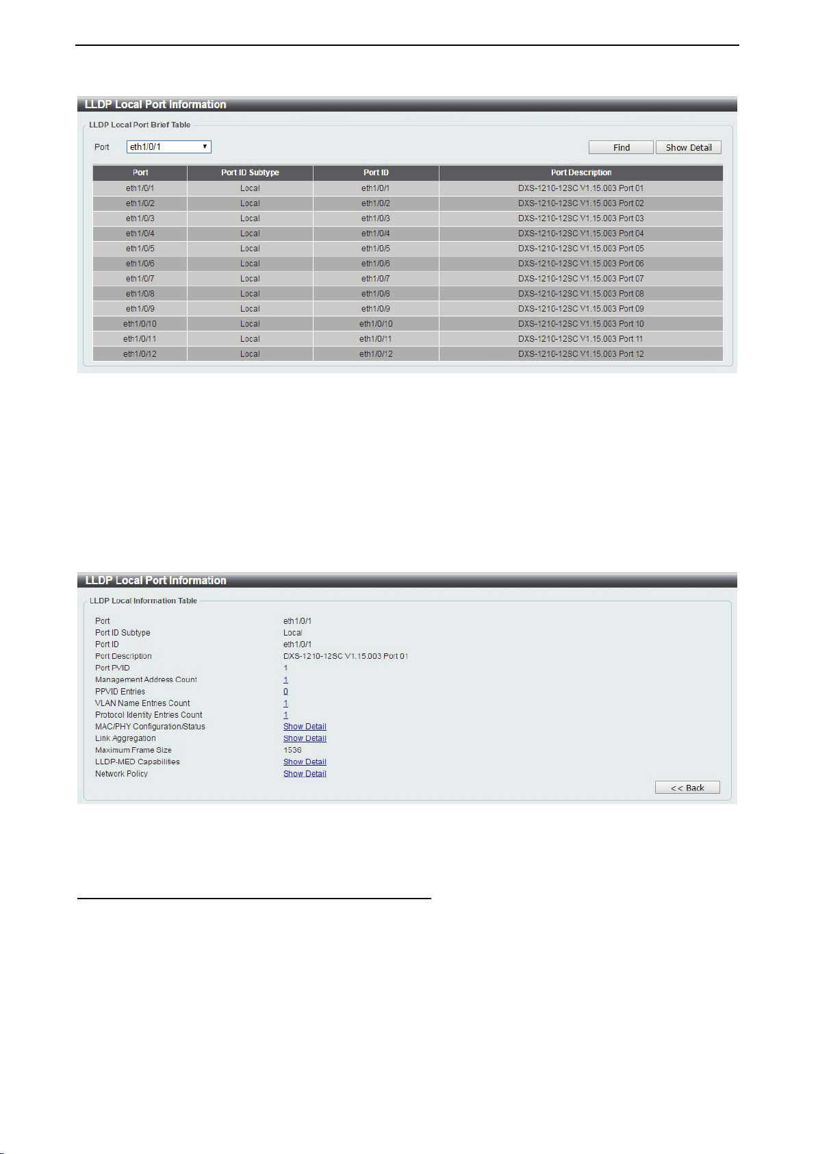
D-Link DXS-1210 Series User Manual
69
Figure 4.111 – L2 Features > LLDP > LLDP Local Port Information
Port: Displays the port number.
Port ID Subtype: Displays the port ID subtype.
Port ID: Displays the port ID (Unit number/Port number).
Port Description: Displays the port description.
Click Find to displays more information for the specified port.
After clicking the Show Detail button, the following page will appear.
Figure 4.112 – L2 Features > LLDP > LLDP Local Port Information – Show Detail
Click the Back button to return to the previous window.
L2 Features > LLDP > LLDP Neighbor Port Information
This LLDP Neighbor Port Information page allows you to view the information on a per-port basis for
populating outbound LLDP advertisements in the local port brief table shown below.
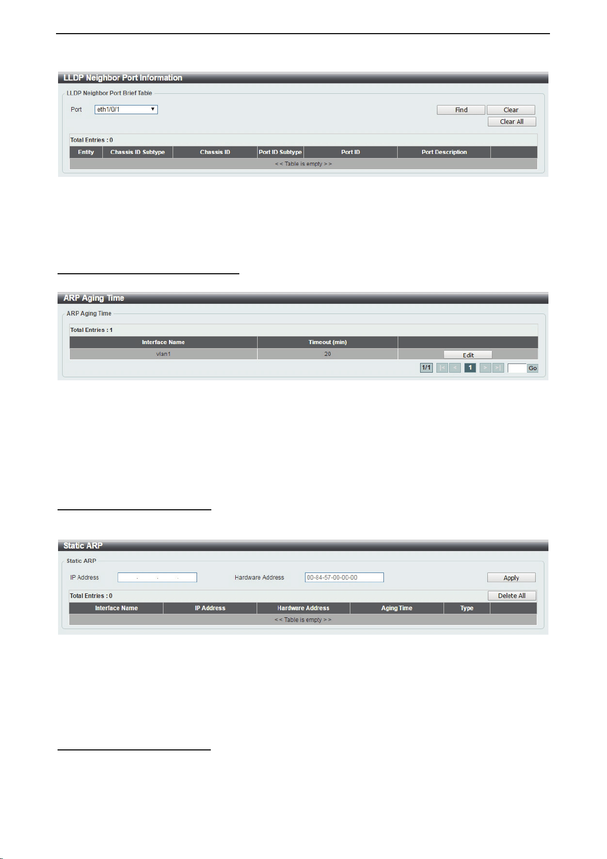
D-Link DXS-1210 Series User Manual
70
Figure 4.113 – L2 Features > LLDP > LLDP Neighbors Port Information
Click the Find button to locate a specific entry based on the information entered.
Click the Clear button to remove the specified port of LLDP neighbor port or click Clear All button to remove
all LLDP neighbor ports.
L3 Features > ARP > ARP Aging Time
The ARP Aging Time page allows you to view and configure the ARP aging time settings.
Figure 4.114 – L3 Features > ARP > ARP Aging Time
Timeout(min): Specifies the aging time of the ARP entry. The default is 5 minutes.
Click the Apply button to save your settings.
Click the Edit button to re-configure the specific entry.
Enter a page number and click the Go button to navigate to a specific page when multiple pages exist.
L3 Features > ARP > Static ARP
The Static ARP page provides information regarding each interface, including the IP address mapped to a
MAC address. Enter an IP Address or Hardware Address and then click Apply to create a new ARP entry.
Figure 4.115 – L3 Features > ARP > Static ARP
Click Edit to modify the Hardware Address.
Click Delete to remove the information from ARP table.
Click Delete All to remove all information from ARP table.
Enter a page number and click the Go button to navigate to a specific page when multiple pages exist.
L3 Features > ARP > ARP Table
The ARP Table page allows you to view and configure the ARP table settings.
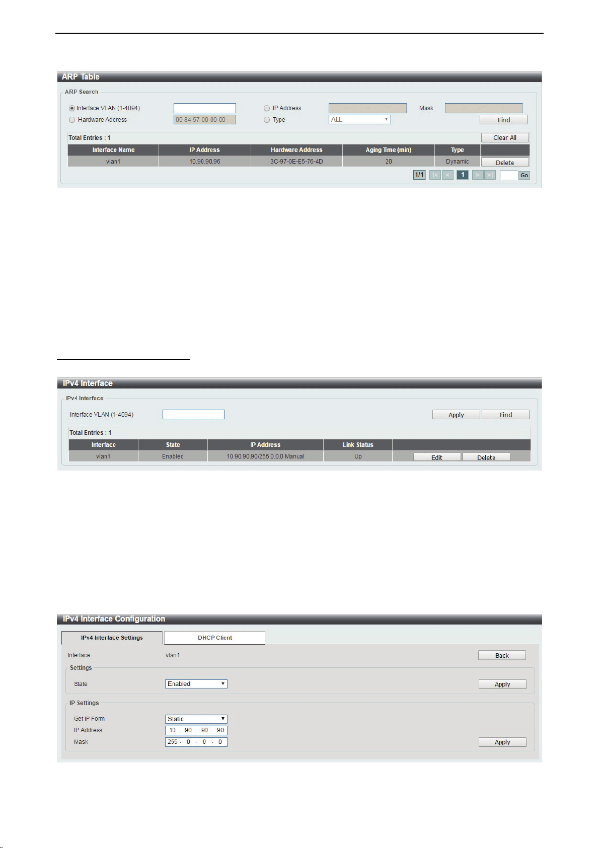
D-Link DXS-1210 Series User Manual
71
Figure 4.116 – L3 Features > ARP > ARP Table
Interface VLAN (1-4094): Select and enter the interface’s VLAN ID.
IP address: Select and enter the IP address to be displayed.
Mask: Enter the mask address for the specified IP address.
Hardware Address: Select and enter the MAC address.
Type: Select the type.
Click the Find button to locate a specific entry based on the information entered.
Click the Delete button to remove the specific entry.
Enter a page number and click the Go button to navigate to a specific page when multiple pages exist.
L3 Features > IPv4 Interface
The IPv4 Interface page allows you to configure the IPv4 Interface settings.
Figure 4.117 – L3 Features > IPv4 Interface
Interface VLAN (1-4094): Enter the VLAN ID of the IPv4 interface.
Click Apply for the settings to take effect.
Click the Find button to display the specific entry.
Click the Edit button to re-configure the specific entry.
Click the Delete button to remove the specific entry.
Enter a page number and click the Go button to navigate to a specific page when multiple pages exist.
After clicking the Edit button, the following window will appear.
Figure 4.118 – L3 Features > IPv4 Interface - Edit
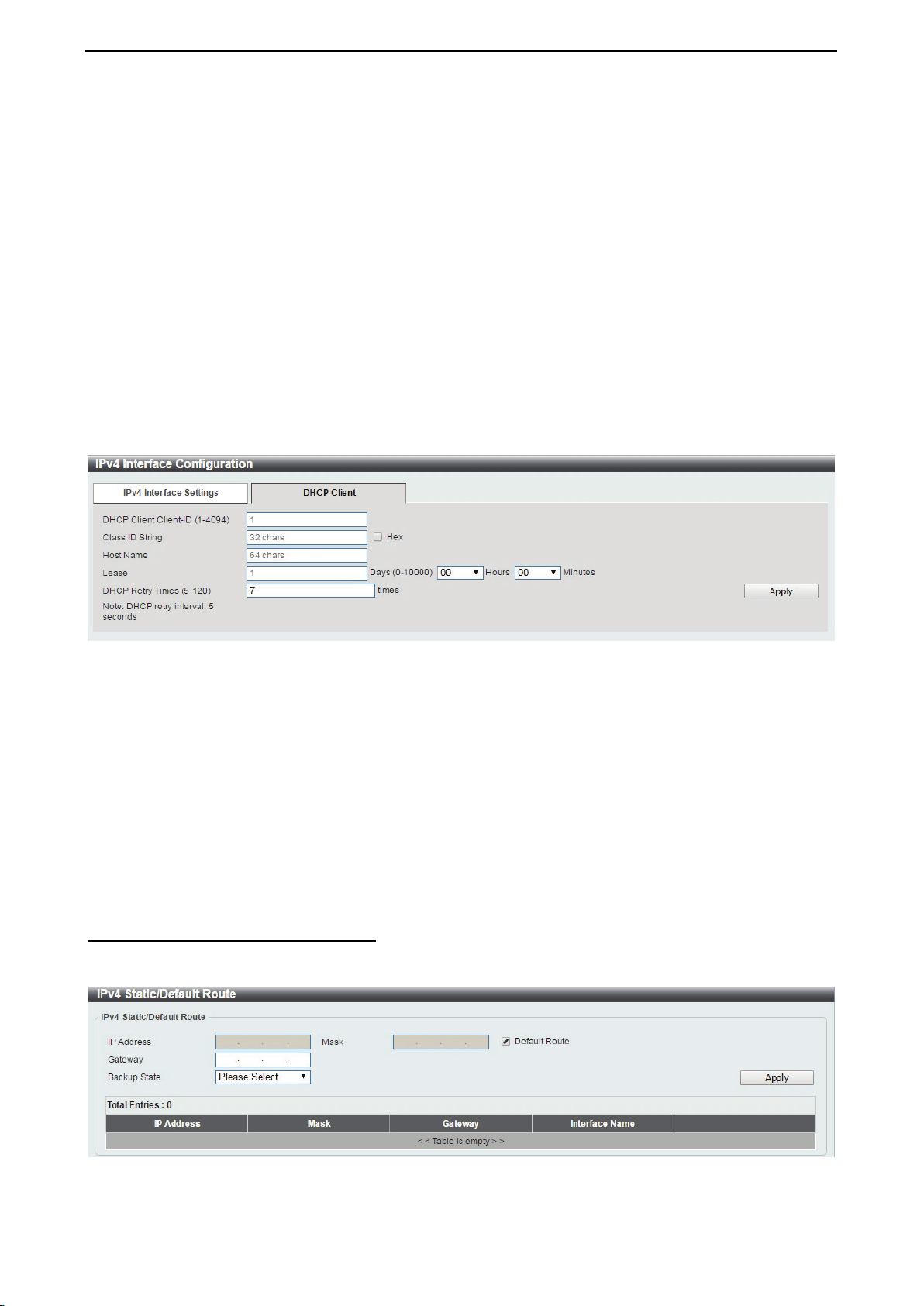
D-Link DXS-1210 Series User Manual
72
Click the Back button to return to the previous window.
State: Select to enable or disable the IPv4 interface’s global state.
Click the Apply button to save your settings.
IP Settings:
Get IP From: Select Static or DHCP. When the Static option is selected, users can enter the IPv4 address
of this interface manually. When the DHCP option is selected, this interface will obtain IPv4 information from
a DHCP server located on the local network.
IP Address: Enter the IPv4 Address for this interface.
Mask: Enter the IPv4 subnet mask for this interface.
Click the Apply button to save your settings.
After clicking the DHCP Client tab, the following page will appear.
Figure 4.119 – L3 Features > IPv4 Interface – DHCP Client
DHCP Client Client-ID (1-4094): Enter the VLAN interface, whose hexadecimal MAC address will be used
as the client ID to be sent with the discover message.
Class ID String: Enter the vendor class identifier with the maximum of 32 characters. Tick the Hex check
box to have the class identifier in the hexadecimal form.
Host Name: Enter the host name.
Lease: Enter the preferred lease time for the IP address to request from the DHCP server. Enter the day
duration of the lease, or select the hour and minute duration of the lease.
DHCP Retry Times (5-120): Enter the DHCP retry times. The value is between 5 and 120 and default is 7
times.
Click the Apply button to save your settings.
L3 Features > IPv4 Static/Default Route
The IPv4 Static/Default Route page allows you to view and configure the IPv4 static and default route
settings.
Figure 4.120 – L3 Features > IPv4 Static/Default Route
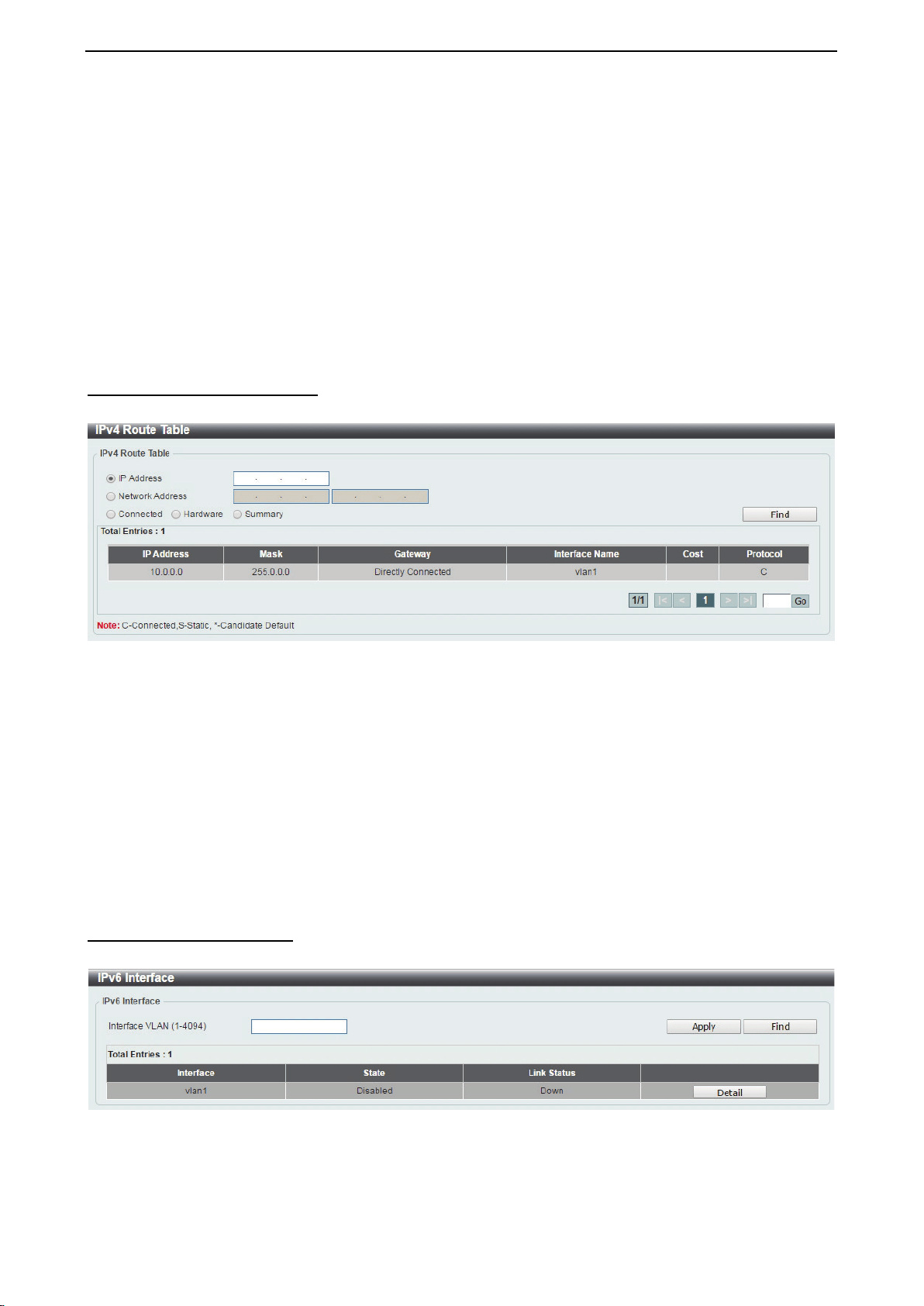
D-Link DXS-1210 Series User Manual
73
IP Address: Specify the network address for the IPv4 static route.
Mask: Specify the mask address for the IPv4 static route. If this is a default route, select the Default Route
checkbox.
Gateway: Enter the gateway address for IPv4 route. If this is a default route, then this is the default gateway.
Backup State: Each network can only have one primary route, and any other routes should be assigned to
the backup state. When the primary route failed, the switch also supports a floating static route, which means
that the user may create an alternative static route to a different next hop. This secondary next hop device
route is considered as a backup static route for when the primary static route is down. If the primary route is
lost, the backup route will become active.
Click Apply button to accept the changes made.
Click the Delete button to remove the specific entry.
L3 Features > IPv4 Route Table
The IPv4 Route Table page is used to view and configure the IPv4 route table settings.
Figure 4.121 – L3 Features > IPv4 Route Table
IP Address: Click the radio button and enter the destination IP address of the route to be displayed. The
longest prefix matched will be displayed.
Network Address: Click the radio button and enter the destination network address of the route to be
displayed.
Connected: Select this option to display only connected routes.
Hardware: Select this option to display only the routes that have been written into hardware.
Summary: Display a summary of the active routing entries.
Click the Find button to locate a specific entry based on the information entered.
Enter a page number and click the Go button to navigate to a specific page when multiple pages exist.
L3 Features > IPv6 Interface
The IPv6 Interface page is used to view and configure the IPv6 interface’s settings.
Figure 4.122 – L3 Features > IPv6 Interface
Interface VLAN (1-4094): Enter the VLAN ID of the IPv6 interface.
Click Apply for the settings to take effect.
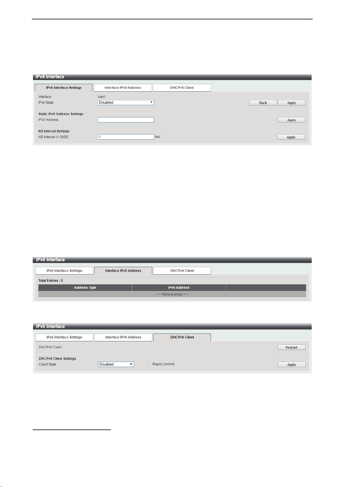
D-Link DXS-1210 Series User Manual
74
Click the Find button to display the specific entry.
Click the Detail button to view and configure more detailed settings for the IPv6 interface entry.
After clicking the Detail button, the following window will be appeared.
Figure 4.123 – L3 Features > IPv6 Interface - Detail
IPv6 State: Select to enable or disable the IPv6 interface’s global state.
Click the Apply button to save your settings.
Static IPv6 Address Setting:
IPv6 Address: Enter the IPv6 address for this IPv6 interface. Select the EUI-64 option to configure an IPv6
address on the interface using the EUI-64 interface ID. Select the Link Local option to configure a link-local
address for the IPv6 interface.
Click the Apply button to save your settings.
NS Interval Settings:
NS Interval (1-3600): Specify the NS interval and the values are between 1 and 3600.
Click the Apply button to save your settings.
After clicking the Interface Address tab located at the top of the page, the following page will appear
Figure 4.124 – L3 Features > IPv6 Interface – Interface IPv6 Address
After clicking the DHCPv6 Client tab located at the top of the page, the following page will appear
Figure 4.125 – L3 Features > IPv6 Interface – DHCPv6 Client
Click the Restart button to restart the DHCPv6 client.
Client State: Select to enable or disable the DHCPv6 client state.
Click the Apply button to save your settings.
L3 Features > IPv6 Neighbor
The user can configure the Switch’s IPv6 neighbor settings. The Switch’s current IPv6 neighbor settings will
be displayed in the table at the bottom of this window.
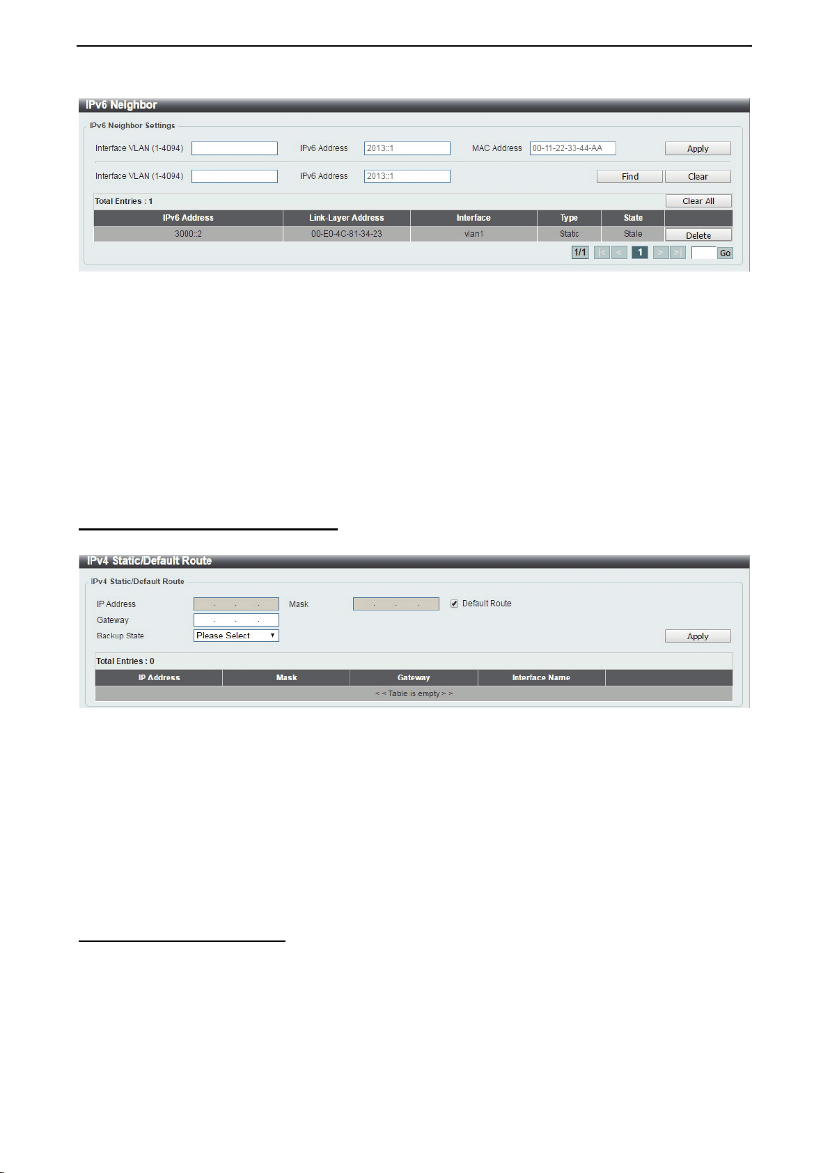
D-Link DXS-1210 Series User Manual
75
Figure 4.126 – L3 Features > IPv6 Neighbor
Interface VLAN (1-4094): Enter the VLAN ID of the IPv6 neighbor.
IPv6 Address: Specifies the neighbor IPv6 address.
MAC Address: Specifies the link layer MAC address.
Click the Apply button to save your settings.
Click Find to locate a specific entry based on the information entered.
Click Clear to clear the specified information entered in the fields.
Click Clear all to clear all the information entered in the fields.
Enter a page number and click the Go button to navigate to a specific page when multiple pages exist.
L3 Features > IPv6 Static/Default Route
The IPv6 Static/Default Route is used to configure the IPv6 static or default routes.
Figure 4.127 – L3 Features > IPv6 Static/Default Route
IPv6 Address/Prefix Length: Enter the destination network for the route, or tick the Defult Route check box
to be assigned to the default route.
Interface VLAN (1-4094): Enter interface’s VLAN ID that will be associated with this route.
Next Hop IPv6 Address: Enter the router’s next hop IPv6 address.
Backup State: Select the backup state option here. Options to choose from are Primary, and Backup.
When the Primary option is selected, the route is specified as the primary route to the destination. When the
Backup option is selected, the route is specified as the backup route to the destination.
Click the Apply button to save your settings.
L3 Features > IPv6 Route Table
The IPv6 Route Table page is used to view and configure the IPv6 route table.
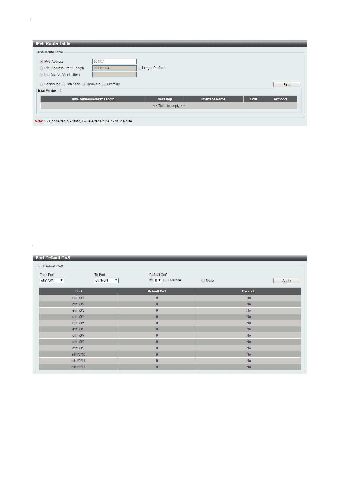
D-Link DXS-1210 Series User Manual
76
Figure 4.128 – L3 Features > IPv6 Route Table
IPv6 Address: Select and enter the IPv6 address to display here.
IPv6 Address/Prefix Length: Select and enter the IPv6 address and prefix length to display here. Select the
Longer Prefixes option to display the route and all of the more specific routes.
Interface VLAN (1-4094): Select and enter the interface’s VLAN ID to display here.
Connected: Select this option to display only connected routes.
Database: Select to view all the related entries in the routing database instead of just the best route.
Hardware: Select this option to display only hardware routes. Hardware routes are routes that have been
written into the hardware chip.
Summary: Display the brief information of the active routing entries.
Click the Find button to locate a specific entry based on the information entered.
QoS > Port Default CoS
The Port Default CoS page allows you to view and configure the port’s default CoS settings.
Figure 4.129 – QoS > Port Default CoS
From Port / To Port: Select the range of ports to be configured.
Default CoS: Select the default CoS option for the specified ports. The values are from 0 to 7. Click the
Override check box to apply the port's default CoS to all packets (tagged or untagged) received by the port.
Select the None option to use the default settings.
Click the Apply button to save your settings.
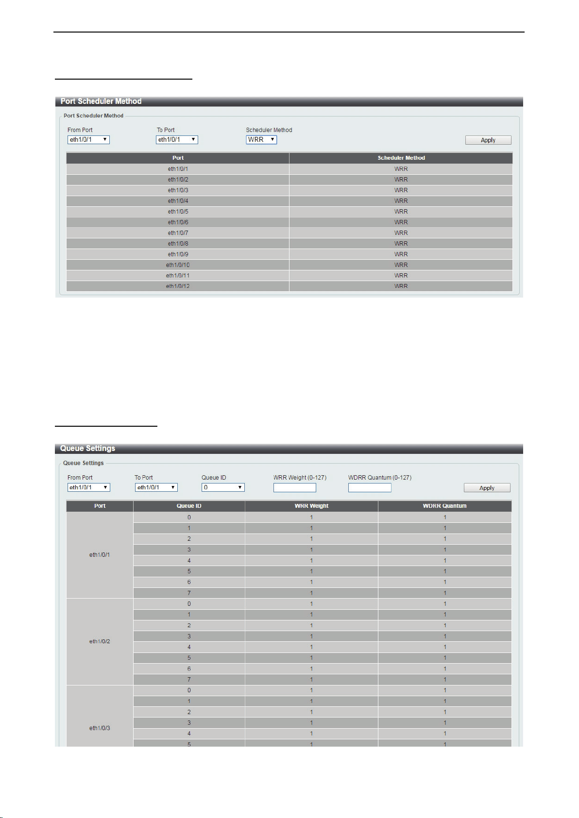
D-Link DXS-1210 Series User Manual
77
QoS > Port Scheduler Method
The Port Scheduler Method page allows you to view and configure the port scheduler method settings.
Figure 4.130 – QoS > Port Scheduler Method
From Port / To Port: Select the range of ports to be configured.
Scheduler Method: Select the scheduler method for the specified ports. Available options are Strict Priority
(SP), Round-Robin (RR), Weighted Round-Robin (WRR), and Weighted Deficit Round-Robin (WDRR). By
default, the output queue scheduling algorithm is WRR.
Click the Apply button to save your settings.
QoS > Queue Settings
The Queue Settings page allows you to configure the queue settings.
Figure 4.131 – QoS > Queue Settings
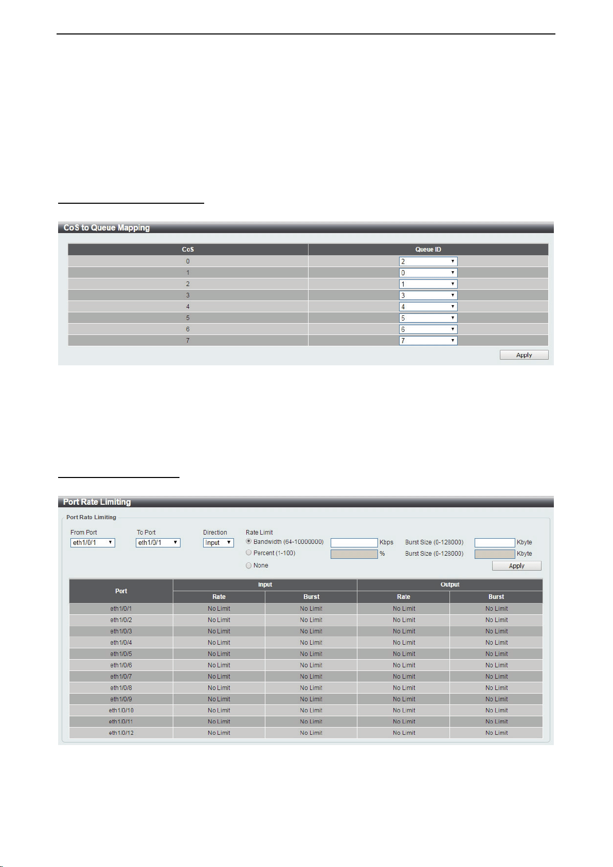
D-Link DXS-1210 Series User Manual
78
From Port / To Port: Select the range of ports to be configured.
Queue ID: Select the queue ID value. The range is between 0 and 7.
WRR Weight (0-127): Enter the WRR weight value. The value is between 0 and 127.
WDRR Quantum (0-127): Enter the WRR quantum value. The value is between 0 and 127.
Click the Apply button to save your settings.
QoS > CoS to Queue Mapping
The CoS to Queue Mapping page allows you to view and configure the CoS-to-Queue mapping settings.
Figure 4.132 – QoS > CoS to Queue Mapping
Queue ID: Select the queue ID that will be mapped to the corresponding CoS value. The value is from are 0
to 7.
Click the Apply button to save your settings.
QoS > Port Rate Limiting
The Port Rate Limiting page allows you to view and configure the port rate limiting settings.
Figure 4.133 – QoS > Port Rate Limiting
From Port / To Port: Select the range of ports to be configured.
Direction: Select the direction. Available options are Input and Output. When Input is selected, the rate

D-Link DXS-1210 Series User Manual
79
limit for ingress packets is configured. When Output is selected, the rate limit for egress packets is
configured.
Rate Limit: Enter the Rate Limit for the specified port.
When Bandwidth is selected, enter the input/output bandwidth value used in the space provided.
This value must be between 64 and 10000000 kbps. Also, enter the Burst Size value in the space
provided. This value must be between 0 and 128000 kilobytes.
When Percent is selected, enter the input/output bandwidth percentage value used in the space
provided. This value must be between 1 and 100 percent (%). Also, enter the Burst Size value in the
space provided. This value must be between 0 and 128000 kilobytes.
Select the None option to remove the rate limit on the specified port(s). The specified limitation
cannot exceed the maximum speed of the specified interface. For the ingress bandwidth limitation,
the ingress can trigger a pause frame or a flow control frame when the received traffic exceeds the
limitation.
Click the Apply button to save your settings.
QoS > Queue Rate Limiting
The Queue Rate Limiting page allows you to view and configure the queue rate limiting settings.
Figure 4.134 – QoS > Queue Rate Limiting
From Port / To Port: Select the range of ports to be configured.
Queue ID: Select the queue ID for the specified ports. The value is between 0 and 7.
Rate Limit: Specify the Rate limit option.
If you selected the Min Bandwidth option, enter the minimum bandwidth rate limit value in the space
provided. This value must be between 8 and 10000000 kbps. Also enter the maximum bandwidth
(Max Bandwidth) rate limit in the space provided. This value must be between 8 and 10000000
kbps.
If you selected the Min Percent option, enter the minimum bandwidth percentage value in the space
provided. This value must be between 1 and 100 percent (%). Also enter the maximum percentage
value (Max Percent) in the space provided. This value must be between 1 and 100 percent (%).
Click the Apply button to save your settings.
QoS > Port Trust State
The Port Trust State page allows you to view and configure the port trust state settings.
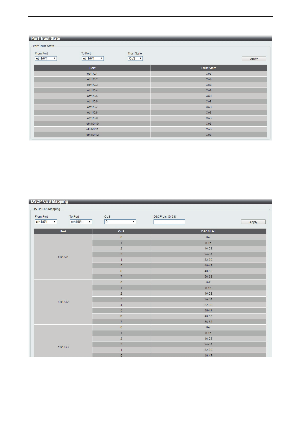
D-Link DXS-1210 Series User Manual
80
Figure 4.135 – QoS > Port Trust State
From Port / To Port: Select the range of ports to be configured.
Trust State: Select the trust state to be CoS or DSCP.
Click the Apply button to save your settings.
QoS > DSCP CoS Mapping
The DSCP CoS Mapping page allows you to view and configure the DSCP CoS mapping settings.
Figure 4.136 – QoS > DSCP CoS Mapping
From Port / To Port: Select the range of ports to be configured.
CoS: Select the CoS priority.
DSCP List (0-63): Enter the DSCP list number.
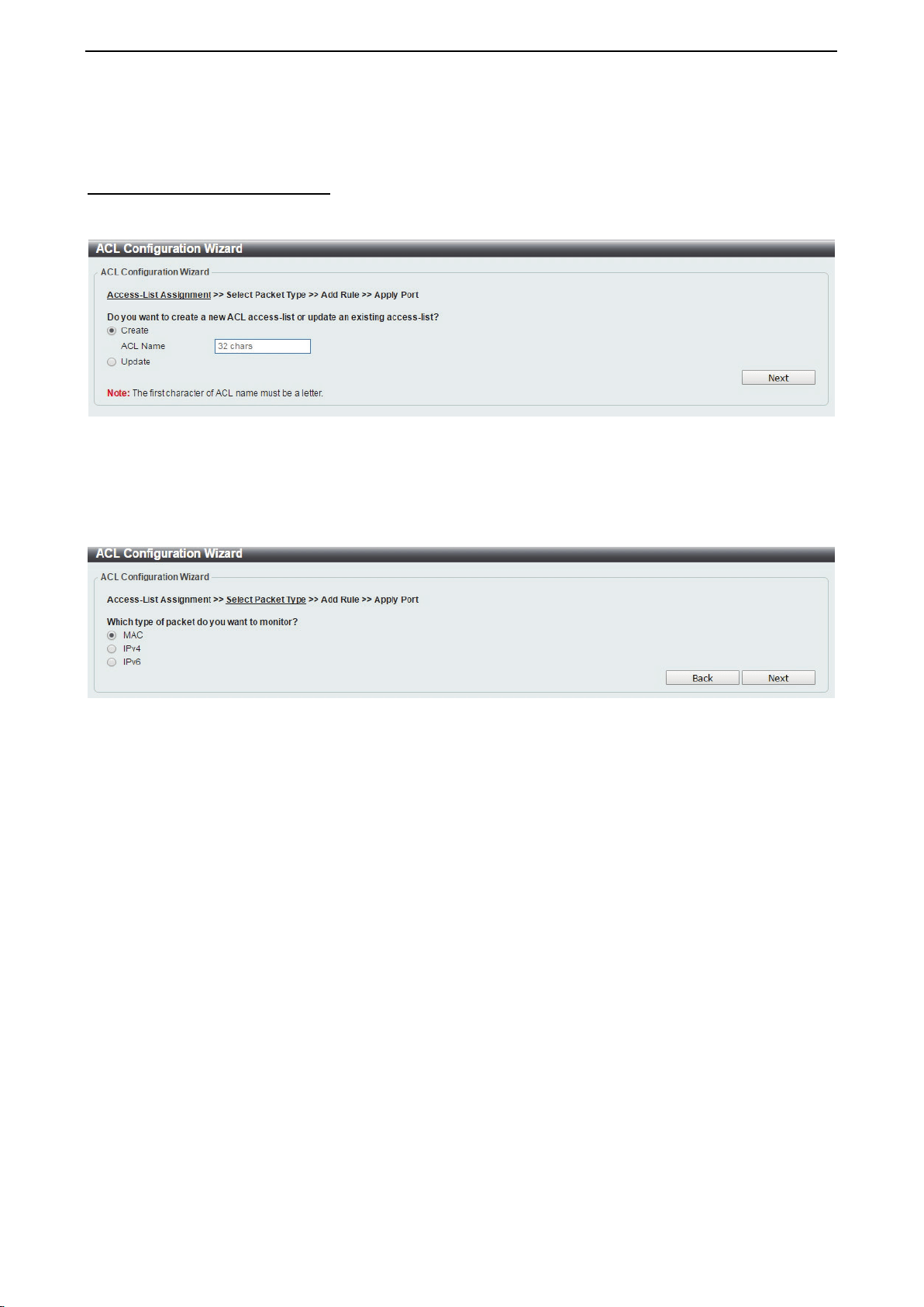
D-Link DXS-1210 Series User Manual
81
Click the Apply button to save your settings.
ACL > ACL Configuration Wizard
The ACL Configuration Wizard page allows you to create a new ACL access list or configure an existing ACL
access list.
Figure 4.137 – ACL > ACL Configuration Wizard
Create: Select Create and enter the ACL Name with a maximum of 32 characters.
Update: Select Update to see a table containing the existing access lists. Select the entry to re-configure it.
Click the Next button to continue.
After clicking the Next button, the following window will appear.
Figure 4.138 – ACL > ACL Configuration Wizard – Packet Type
MAC: Select to create a MAC ACL.
IPv4: Select to create an IPv4 ACL.
IPv6: Select to create an IPv6 ACL.
Click the Back button to return to the previous window.
Click the Next button to continue.
To define the MAC ACL: Select MAC and then click the Next button. Click the MAC Address, Ethernet
Type and 802.1Q VLAN tabs to display the following page:
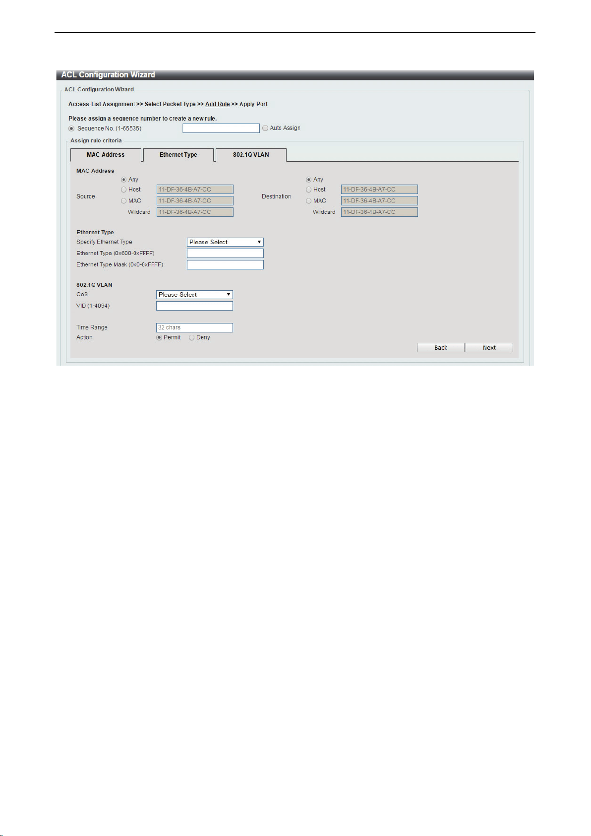
D-Link DXS-1210 Series User Manual
82
Figure 4.139 – ACL > ACL Configuration Wizard – Create MAC ACL
The Add ACL Profile MAC ACL contains the following fields:
Sequence No.(1-65535): Select the ACL rule number. The value is between 1 and 65535. Select Auto
Assign to automatically generate an ACL rule number for this entry.
Source: Select and enter the source information. Available options are Any, Host, and MAC. When Any is
selected, any source traffic will be evaluated according to the conditions of this rule. When Host is specified,
enter the source host’s MAC address. When MAC is selected, the Wildcard will also be available. Enter the
source MAC address and wildcard value in the spaces provided.
Destination: Select and enter the destination information. Available options are Any, Host, and MAC. When
Any option is selected, any destination traffic will be evaluated according to the conditions of this rule. When
Host is selected, enter the destination host’s MAC address. When MAC is selected, the Wildcard will also
be available. Enter the destination MAC address and wildcard value in the spaces provided.
Specify Ethernet Type: Select the Ethernet type option. Options to choose from are aarp, appletalk,
decent-iv, etype-6000, etype-8042, lat, lavc-sca, mop-console, mop-dump, vines-echo, vines-ip, xns-
idp, and arp.
Ethernet Type (0x600-0xFFFF): Enter the Ethernet type hexadecimal value. The value is between 0x600
and 0xFFFF. When any Ethernet type profile is selected in the Specify Ethernet Type drop-down list, the
appropriate hexadecimal value will automatically be entered.
Ethernet Type Mask (0x0-0xFFFF): Enter the Ethernet type mask hexadecimal value. The value is between
0x0 and 0xFFFF. When any Ethernet type profile is selected in the Specify Ethernet Type drop-down list,
the appropriate hexadecimal value will automatically be entered.
CoS: Select the CoS value used. This value is between 0 and 7.
VID (1-4094): Enter the VLAN ID that will be associated with this ACL rule. The value should be between 1
and 4094.
Time Range: Enter the time range.
Action: Select the action that this rule will take. The values are Permit and Deny.
Click the Back button to return to the previous window.
Click the Next button to continue.
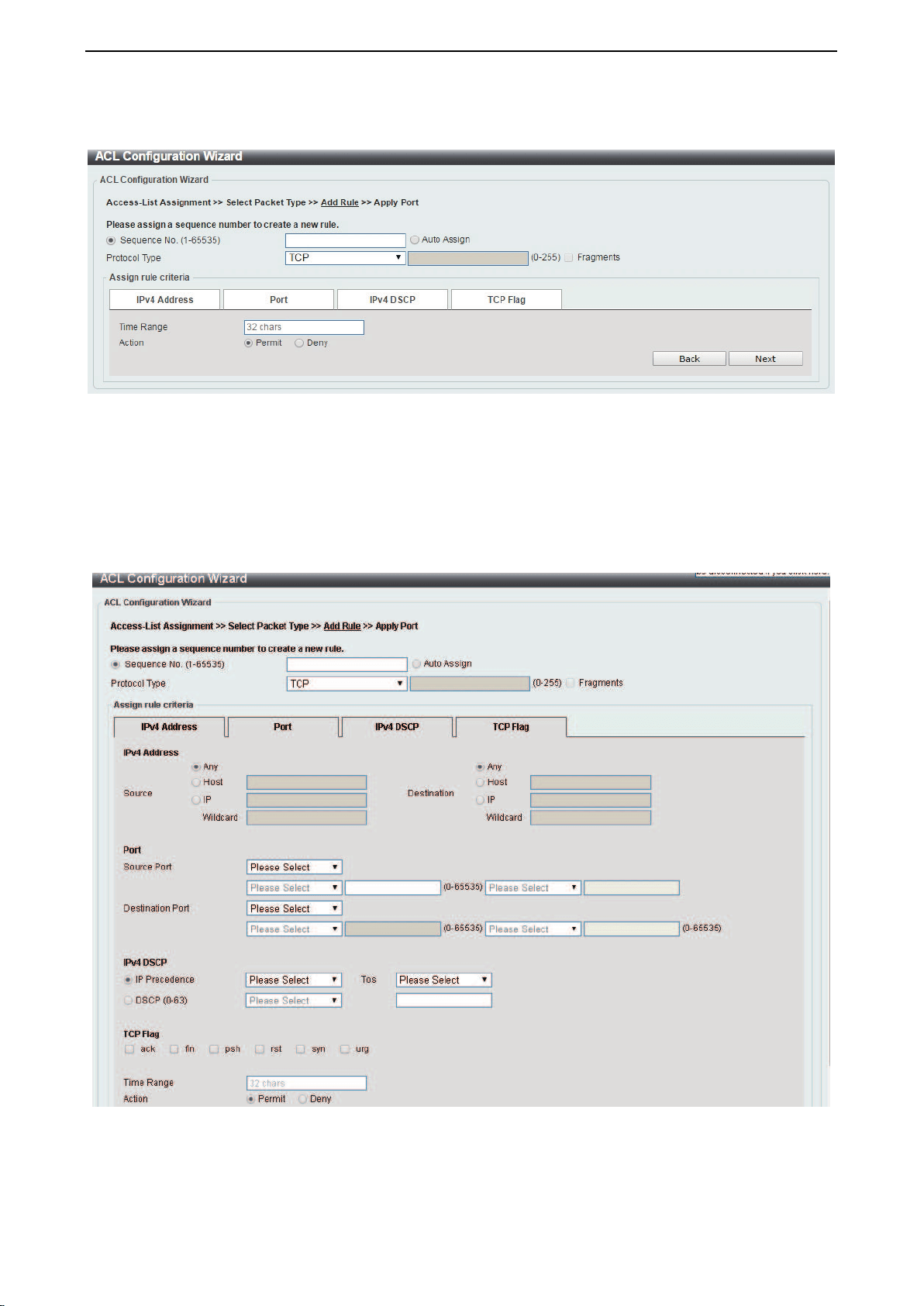
D-Link DXS-1210 Series User Manual
83
To define the IPv4 ACL: Select IPv4 and then click the Next button. Click the IPv4 Address, Port, IPv4
DSCP and TCP Flag tabs to display the following page:
Figure 4.140 – ACL > ACL Configuration Wizard – Create IPv4 ACL
Sequence No. (1-65535): Select and enter the ACL rule number. This value must be between 1 and 65535.
Select Auto Assign to automatically generate an ACL rule number for this entry.
Protocol Type: Select the protocol type option. Options to choose from are TCP, UDP, ICMP, EIGRP, ESP,
GRE, IGMP, OSPF, PIM, VRRP, IP-in-IP, PCP, Protocol ID, and None.
After selecting TCP as the Protocol Type, Click the IPv4 Address, Port, IPv4 DSCP and TCP Flag tabs to
display the following page:
Figure 4.141 – ACL > ACL Configuration Wizard – Create IPv4 ACL-TCP
Source: Select the source information. The values are Any, Host and IP.
Destination: Select the destination information. The values are Any, Host and IP.
Source Port: Select the source port value.

D-Link DXS-1210 Series User Manual
84
Destination Port: Select the destination port value.
IP Precedence: Select the IP precedence value. Options to choose from are 0 (routine), 1 (priority), 2
(immediate), 3 (flash), 4 (flash-override), 5 (critical), 6 (internet), and 7 (network).
ToS: Specify the Type-of-Service (ToS) value that will be used. Options to choose from are 0 (normal), 1
(min-monetary-cost), 2 (max-reliability), 3, 4 (max-throughput), 5, 6, 7, 8 (min-delay), 9, 10, 11, 12, 13,
14, and 15.
DSCP (0-63): Enter the DSCP value. And the range is between 0 and 63.
TCP Flag: Select the appropriate TCP flag option to include the flag in this rule. Options to choose from are
ack, fin, psh, rst, syn, and urg.
Time Range: Enter the time range.
Action: Select the action for the rule. The values are Permit and Deny.
After selecting UDP as the Protocol Type, click the IPv4 Address, Port and IPv4 DSCP tabs to display the
following page:
Figure 4.142 – ACL > ACL Configuration Wizard – Create IPv4 ACL-UDP
Source: Select the source information. The values are Any, Host and IP.
Destination: Select the destination information. The values are Any, Host and IP.
Source Port: Select the source port value.
Destination Port: Select the destination port value.
IP Precedence: Select the IP precedence value. Options to choose from are 0 (routine), 1 (priority), 2
(immediate), 3 (flash), 4 (flash-override), 5 (critical), 6 (internet), and 7 (network).
ToS: Specify the Type-of-Service (ToS) value that will be used. Options to choose from are 0 (normal), 1
(min-monetary-cost), 2 (max-reliability), 3, 4 (max-throughput), 5, 6, 7, 8 (min-delay), 9, 10, 11, 12, 13,
14, and 15.
DSCP (0-63): Enter the DSCP value. And the range is between 0 and 63.
TCP Flag: Select the appropriate TCP flag option to include the flag in this rule. Options to choose from are
ack, fin, psh, rst, syn, and urg.
Time Range: Enter the time range.
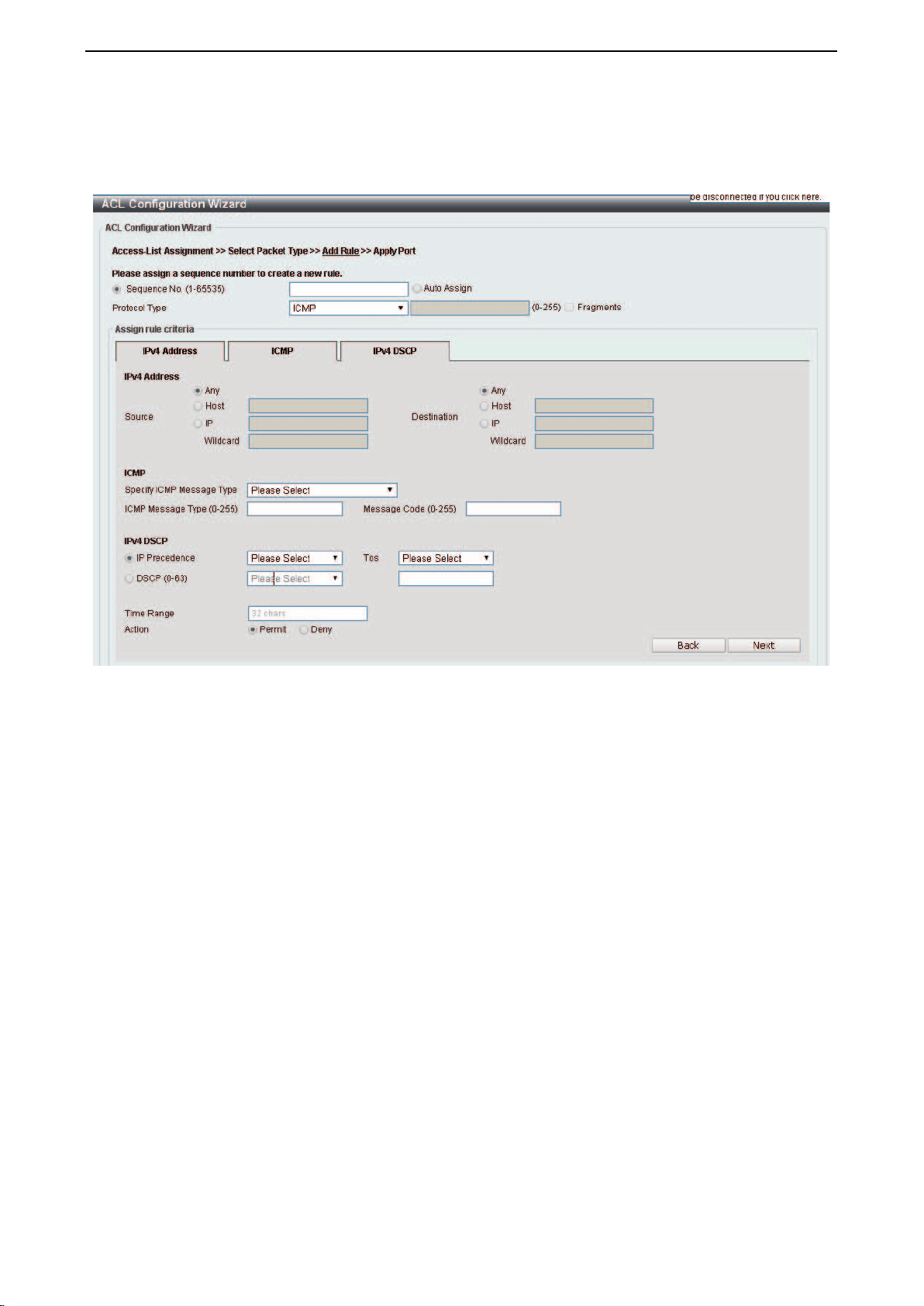
D-Link DXS-1210 Series User Manual
85
Action: Select the action for the rule. The values are Permit and Deny.
After selecting ICMP as the Protocol Type, click the IPv4 Address, ICMP and IPv4 DSCP tabs to display
the following page:
Figure 4.143 – ACL > ACL Configuration Wizard – Create IPv4 ACL-ICMP
Source: Select the source information. The values are Any, Host and IP.
Destination: Select the destination information. The values are Any, Host and IP.
IP Precedence: Select the IP precedence value. Options to choose from are 0 (routine), 1 (priority), 2
(immediate), 3 (flash), 4 (flash-override), 5 (critical), 6 (internet), and 7 (network).
ToS: Select the Type-of-Service (ToS) value that will be used. Options to choose from are 0 (normal), 1
(min-monetary-cost), 2 (max-reliability), 3, 4 (max-throughput), 5, 6, 7, 8 (min-delay), 9, 10, 11, 12, 13,
14, and 15.
DSCP (0-63): Select the DSCP value. And the range is between 0 and 63.
Specify ICMP Message Type: Specify the ICMP message type.
ICMP Message Type (0-255): When the ICMP Message Type is not selected, enter the ICMP Message
Type numerical value used. When the ICMP Message Type is selected, this numerical value will
automatically be entered.
Message Code (0-255): When the ICMP Message Type is not selected, enter the Message Code numerical
value used. When the ICMP Message Type is selected, this numerical value will automatically be entered.
Time Range: Enter the time range.
Action: Specify the action for the rule. The values are Permit and Deny.
After selecting EIGRP as the Protocol Type, click the IPv4 Address and IPv4 DSCP tabs to display the
following page:

D-Link DXS-1210 Series User Manual
86
Figure 4.144 – ACL > ACL Configuration Wizard – Create IPv4 ACL-EIGRP
Source: Select the source information. The values are Any, Host and IP.
Destination: Select the destination information. The values are Any, Host and IP.
Fragments: Specify the Fragments option to include packet fragment filtering.
Source: Select the source information. The values are Any, Host and IP.
Destination: Select the destination information. The values are Any, Host and IP.
IP Precedence: Select the IP precedence value. Options to choose from are 0 (routine), 1 (priority), 2
(immediate), 3 (flash), 4 (flash-override), 5 (critical), 6 (internet), and 7 (network).
ToS: Select the Type-of-Service (ToS) value that will be used. Options to choose from are 0 (normal), 1
(min-monetary-cost), 2 (max-reliability), 3, 4 (max-throughput), 5, 6, 7, 8 (min-delay), 9, 10, 11, 12, 13,
14, and 15.
DSCP (0-63): Select the DSCP value. And the range is between 0 and 63.
Time Range: Enter the time range.
Action: Select the action for the rule. The values are Permit and Deny.
After selecting ESP as the Protocol Type, click the IPv4 Address and IPv4 DSCP tabs to display the
following page:
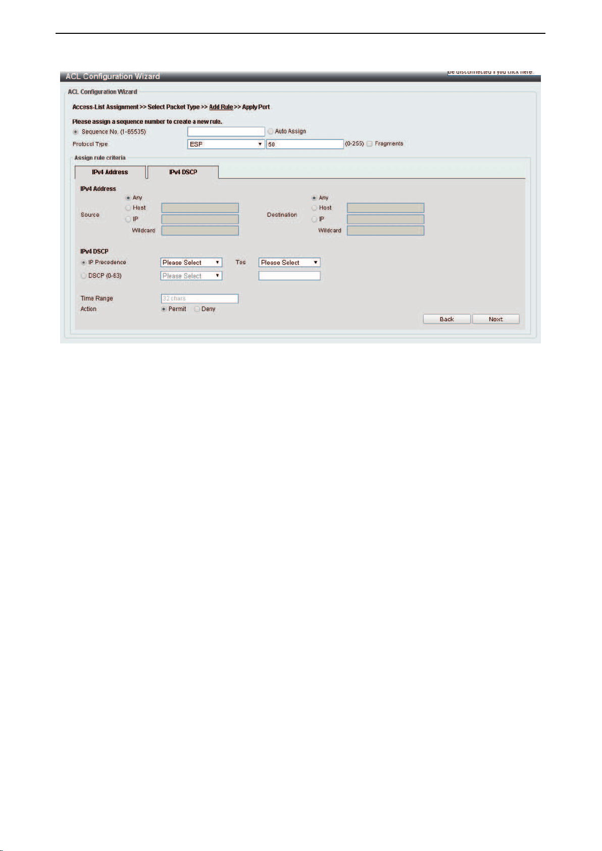
D-Link DXS-1210 Series User Manual
87
Figure 4.145 – ACL > ACL Configuration Wizard – Create IPv4 ACL-ESP
Source: Select the source information. The values are Any, Host and IP.
Destination: Select the destination information. The values are Any, Host and IP.
IP Precedence: Select the IP precedence value. Options to choose from are 0 (routine), 1 (priority), 2
(immediate), 3 (flash), 4 (flash-override), 5 (critical), 6 (internet), and 7 (network).
ToS: Select the Type-of-Service (ToS) value that will be used. Options to choose from are 0 (normal), 1
(min-monetary-cost), 2 (max-reliability), 3, 4 (max-throughput), 5, 6, 7, 8 (min-delay), 9, 10, 11, 12, 13,
14, and 15.
DSCP (0-63): Select the DSCP value. And the range is between 0 and 63.
Time Range: Enter the time range.
Action: Select the action for the rule. The values are Permit and Deny.
After selecting GRE as the Protocol Type, click the IPv4 Address and IPv4 DSCP tabs to display the
following page:
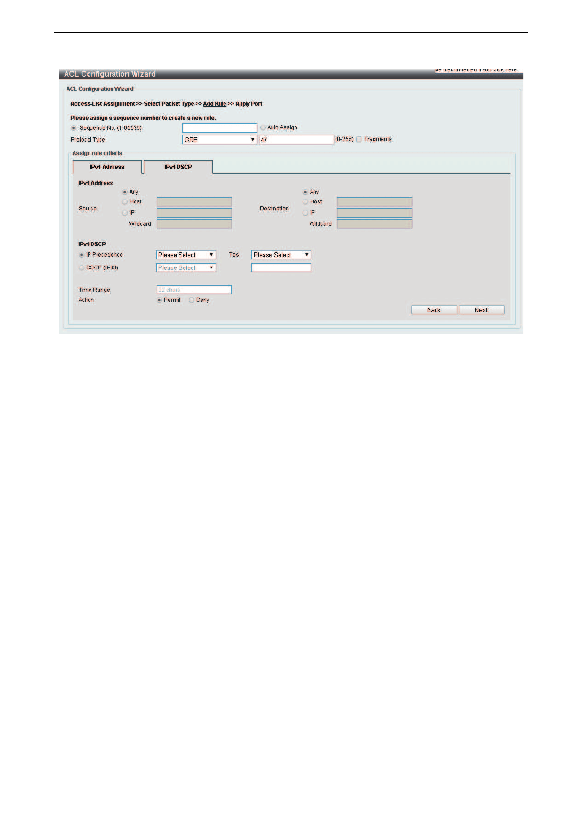
D-Link DXS-1210 Series User Manual
88
Figure 4.146 – ACL > ACL Configuration Wizard – Create IPv4 ACL-GRE
Fragments: Select the Fragments option to include packet fragment filtering.
Source: Select the source information. The values are Any, Host and IP.
Destination: Select the destination information. The values are Any, Host and IP.
IP Precedence: Select the IP precedence value. Options to choose from are 0 (routine), 1 (priority), 2
(immediate), 3 (flash), 4 (flash-override), 5 (critical), 6 (internet), and 7 (network).
ToS: Specify the Type-of-Service (ToS) value that will be used. Options to choose from are 0 (normal), 1
(min-monetary-cost), 2 (max-reliability), 3, 4 (max-throughput), 5, 6, 7, 8 (min-delay), 9, 10, 11, 12, 13,
14, and 15.
DSCP (0-63): Select the DSCP value. And the range is between 0 and 63.
Time Range: Enter the time range.
Action: Select the action for the rule. The values are Permit and Deny.
After selecting IGMP as the Protocol Type, click the IPv4 Address, and IPv4 DSCP tabs to display the
following page:

D-Link DXS-1210 Series User Manual
89
Figure 4.147 – ACL > ACL Configuration Wizard – Create IPv4 ACL-IGMP
Fragments: Select the Fragments option to include packet fragment filtering.
Source: Select the source information. The values are Any, Host and IP.
Destination: Select the destination information. The values are Any, Host and IP.
IP Precedence: Select the IP precedence value. Options to choose from are 0 (routine), 1 (priority), 2
(immediate), 3 (flash), 4 (flash-override), 5 (critical), 6 (internet), and 7 (network).
ToS: Specify the Type-of-Service (ToS) value that will be used. Options to choose from are 0 (normal), 1
(min-monetary-cost), 2 (max-reliability), 3, 4 (max-throughput), 5, 6, 7, 8 (min-delay), 9, 10, 11, 12, 13,
14, and 15.
DSCP (0-63): Select the DSCP value. And the range is between 0 and 63.
Time Range: Enter the time range.
Action: Select the action for the rule. The values are Permit and Deny.
After selecting OSPF as the Protocol Type, click the IPv4 Address, and IPv4 DSCP to display the following
page:

D-Link DXS-1210 Series User Manual
90
Figure 4.148 – ACL > ACL Configuration Wizard – Create IPv4 ACL-OSPF
Fragments: Select the Fragments option to include packet fragment filtering.
Source: Select the source information. The values are Any, Host and IP.
Destination: Select the destination information. The values are Any, Host and IP.
IP Precedence: Select the IP precedence value. Options to choose from are 0 (routine), 1 (priority), 2
(immediate), 3 (flash), 4 (flash-override), 5 (critical), 6 (internet), and 7 (network).
ToS: Specify the Type-of-Service (ToS) value that will be used. Options to choose from are 0 (normal), 1
(min-monetary-cost), 2 (max-reliability), 3, 4 (max-throughput), 5, 6, 7, 8 (min-delay), 9, 10, 11, 12, 13,
14, and 15.
DSCP (0-63): Select the DSCP value. And the range is between 0 and 63.
Time Range: Enter the time range.
Action: Select the action for the rule. The values are Permit and Deny.
After selecting PIM as the Protocol Type, click the IPv4 Address, and IPv4 DSCP tabs to display the
following page:

D-Link DXS-1210 Series User Manual
91
Figure 4.149 – ACL > ACL Configuration Wizard – Create IPv4 ACL-PIM
Fragments: Select the Fragments option to include packet fragment filtering.
Source: Select the source information. The values are Any, Host and IP.
Destination: Select the destination information. The values are Any, Host and IP.
IP Precedence: Select
the IP precedence value used. Options to choose from are 0 (routine), 1 (priority), 2
(immediate), 3 (flash), 4 (flash-override), 5 (critical), 6 (internet), and 7 (network).
ToS: Select the Type-of-Service (ToS) value that will be used. Options to choose from are 0 (normal), 1
(min-monetary-cost), 2 (max-reliability), 3, 4 (max-throughput), 5, 6, 7, 8 (min-delay), 9, 10, 11, 12, 13,
14, and 15.
DSCP (0-63): Select the DSCP value. And the range is between 0 and 63.
Time Range: Enter the time range.
Action: Select the action for the rule. The values are Permit and Deny.
After selecting VRRP as the Protocol Type, click the IPv4 Address, and IPv4 DSCP tabs to display the
following page:

D-Link DXS-1210 Series User Manual
92
Figure 4.150 – ACL > ACL Configuration Wizard – Create IPv4 ACL-VRRP
Fragments: Select the Fragments option to include packet fragment filtering.
Source: Select the source information. The values are Any, Host and IP.
Destination: Select the destination information. The values are Any, Host and IP.
IP Precedence: Select the IP precedence value. Options to choose from are 0 (routine), 1 (priority), 2
(immediate), 3 (flash), 4 (flash-override), 5 (critical), 6 (internet), and 7 (network).
ToS: Select the Type-of-Service (ToS) value that will be used. Options to choose from are 0 (normal), 1
(min-monetary-cost), 2 (max-reliability), 3, 4 (max-throughput), 5, 6, 7, 8 (min-delay), 9, 10, 11, 12, 13,
14, and 15.
DSCP (0-63): Select the DSCP value. And the range is between 0 and 63.
Time Range: Enter the time range.
Action: Select the action for the rule. The values are Permit and Deny.
After selecting IP-in-IP as the Protocol Type, click the IPv4 Address, and IPv4 DSCP tabs to display the
following page:

D-Link DXS-1210 Series User Manual
93
Figure 4.151 – ACL > ACL Configuration Wizard – Create IPv4 ACL-IP in IP
Fragments: Select the Fragments option to include packet fragment filtering.
Source: Select the source information. The values are Any, Host and IP.
Destination: Select the destination information. The values are Any, Host and IP.
IP Precedence: Select the IP precedence value. Options to choose from are 0 (routine), 1 (priority), 2
(immediate), 3 (flash), 4 (flash-override), 5 (critical), 6 (internet), and 7 (network).
ToS: Select the Type-of-Service (ToS) value that will be used. Options to choose from are 0 (normal), 1
(min-monetary-cost), 2 (max-reliability), 3, 4 (max-throughput), 5, 6, 7, 8 (min-delay), 9, 10, 11, 12, 13,
14, and 15.
DSCP (0-63): Select the DSCP value. And the range is between 0 and 63.
Time Range: Enter the time range.
Action: Select the action for the rule. The values are Permit and Deny.
After selecting PCP as the Protocol Type, click the IPv4 Address, and IPv4 DSCP tabs to display the
following page:
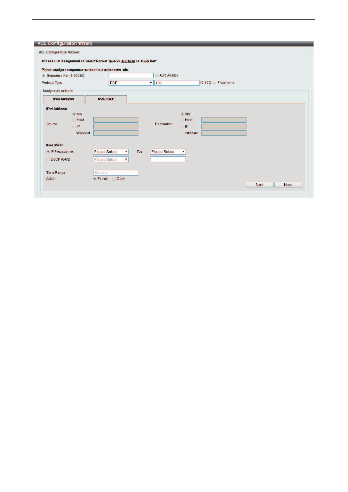
D-Link DXS-1210 Series User Manual
94
Figure 4.152 – ACL > ACL Configuration Wizard – Create IPv4 ACL-PCP
Fragments: Select the Fragments option to include packet fragment filtering.
Source: Select the source information. The values are Any, Host and IP.
Destination: Select the destination information. The values are Any, Host and IP.
IP Precedence: Select the IP precedence value. Options to choose from are 0 (routine), 1 (priority), 2
(immediate), 3 (flash), 4 (flash-override), 5 (critical), 6 (internet), and 7 (network).
ToS: Select the Type-of-Service (ToS) value that will be used. Options to choose from are 0 (normal), 1
(min-monetary-cost), 2 (max-reliability), 3, 4 (max-throughput), 5, 6, 7, 8 (min-delay), 9, 10, 11, 12, 13,
14, and 15.
DSCP (0-63): Select the DSCP value. And the range is between 0 and 63.
Time Range: Enter the time range.
Action: Select the action for the rule. The values are Permit and Deny.
After selecting Protocol ID as the Protocol Type, click the IPv4 Address, and IPv4 DSCP tabs to display
the following page:
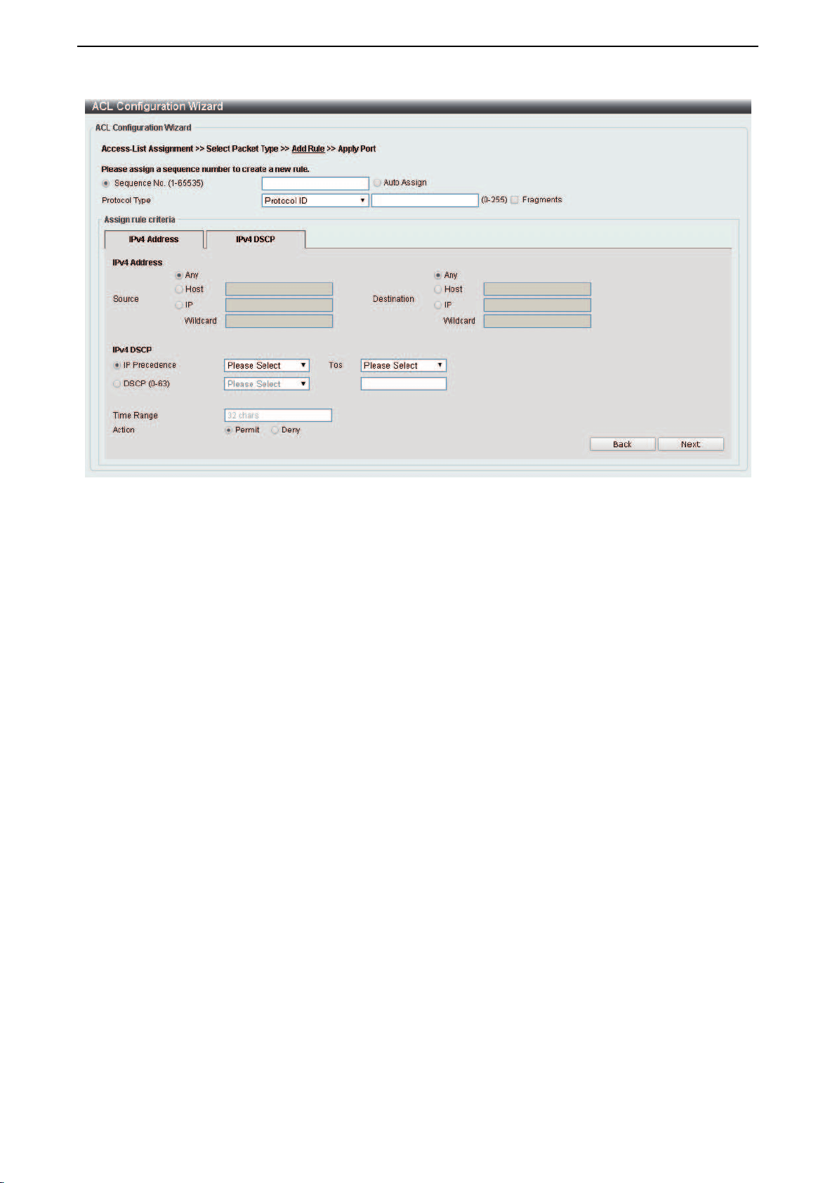
D-Link DXS-1210 Series User Manual
95
Figure 4.153 – ACL > ACL Configuration Wizard – Create IPv4 ACL-Protocol ID
Fragments: Select the Fragments option to include packet fragment filtering.
Source: Select the source information. The values are Any, Host and IP.
Destination: Select the destination information. The values are Any, Host and IP.
IP Precedence: Select the IP precedence value used. Options to choose from are 0 (routine), 1 (priority), 2
(immediate), 3 (flash), 4 (flash-override), 5 (critical), 6 (internet), and 7 (network).
ToS: Select the Type-of-Service (ToS) value that will be used. Options to choose from are 0 (normal), 1
(min-monetary-cost), 2 (max-reliability), 3, 4 (max-throughput), 5, 6, 7, 8 (min-delay), 9, 10, 11, 12, 13,
14, and 15.
DSCP (0-63): Select the DSCP value. And the range is between 0 and 63.
Time Range: Enter the time range.
Action: Select the action for the rule. The values are Permit and Deny.
After selecting None as the Protocol Type, click the associated tabs with IPv4 Address, and IPv4 DSCP
tabs to display the following page:
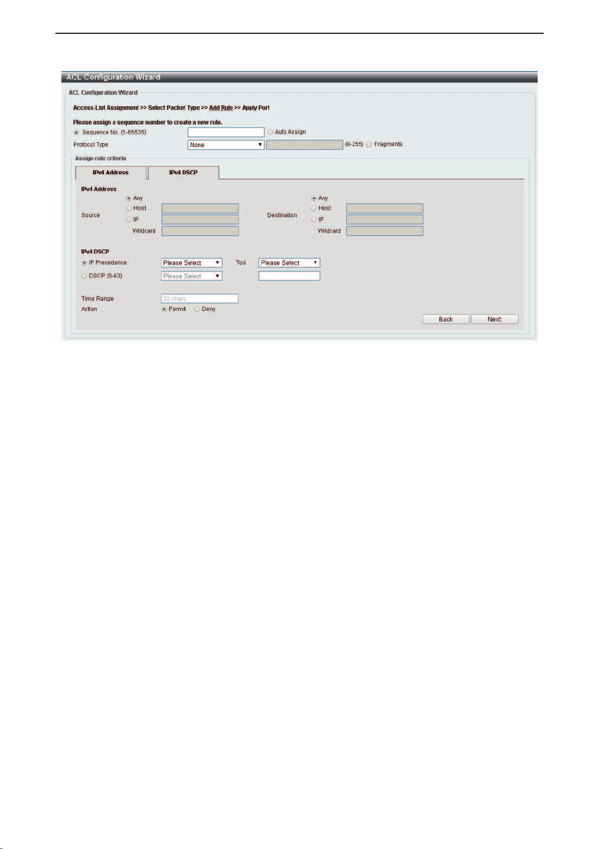
D-Link DXS-1210 Series User Manual
96
Figure 4.154 – ACL > ACL Configuration Wizard – Create IPv4 ACL-None
Fragments: Select the Fragments option to include packet fragment filtering.
Source: Select the source information. The values are Any, Host and IP.
Destination: Select the destination information. The values are Any, Host and IP.
IP Precedence: Select the IP precedence value. Options to choose from are 0 (routine), 1 (priority), 2
(immediate), 3 (flash), 4 (flash-override), 5 (critical), 6 (internet), and 7 (network).
ToS: Select the Type-of-Service (ToS) value that will be used. Options to choose from are 0 (normal), 1
(min-monetary-cost), 2 (max-reliability), 3, 4 (max-throughput), 5, 6, 7, 8 (min-delay), 9, 10, 11, 12, 13,
14, and 15.
DSCP (0-63): Select the DSCP value. And the range is between 0 and 63.
Time Range: Enter the time range.
Action: Select the action for the rule. The values are Permit and Deny.
Click the Back button to return to the previous window.
Click the Next button to continue.
To define the IPv6 ACL: Select IPv6 and then click the Next button. Select TCP option as the Protocol
Type and click the IPv6 Address, Port, IPv6 DSCP, TCP Flag and Flow Label tabs to display the following
page:
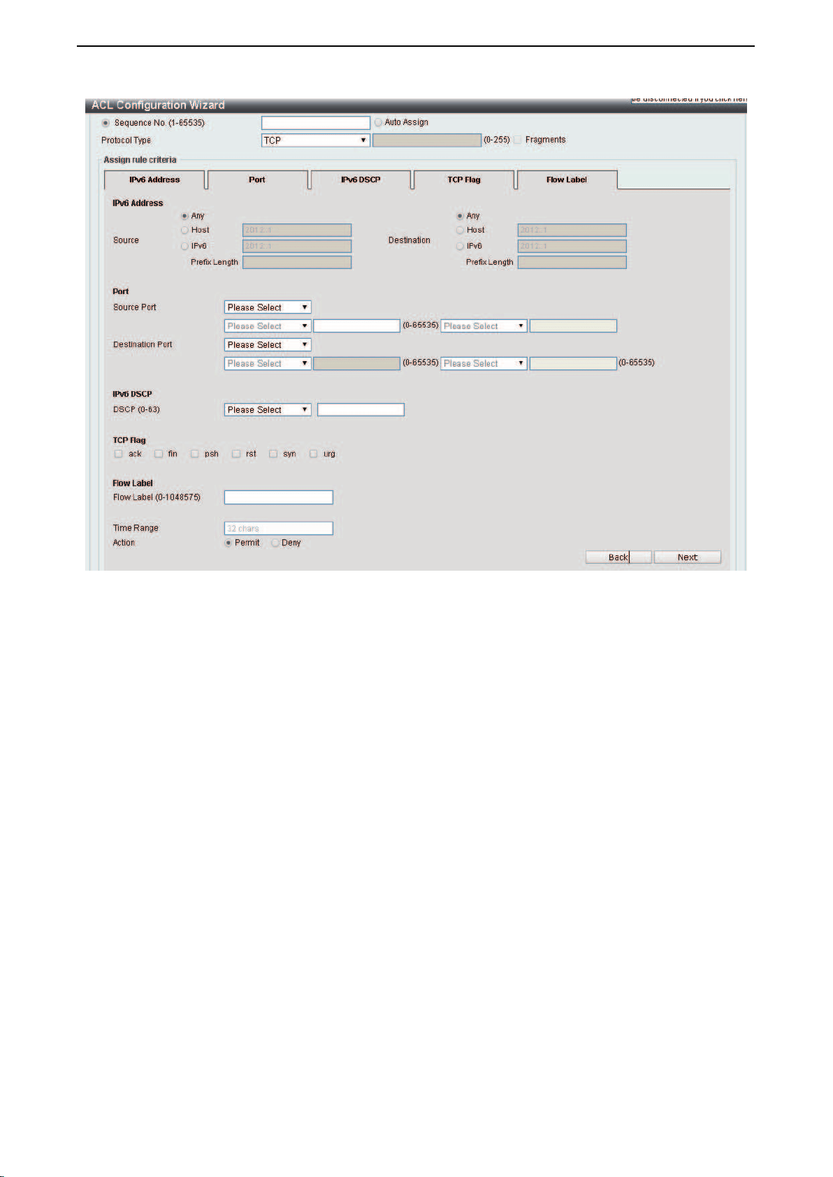
D-Link DXS-1210 Series User Manual
97
Figure 4.155 – ACL > ACL Configuration Wizard – Create IPv6 ACL-TCP
Source Port: Select the source port value.
Destination Port: Select the destination port value.
IPv6 DSCP (0-63): Select the DSCP value. And the range is between 0 and 63.
TCP Flag: Tick the appropriate TCP flag option to include the flag in this rule. Options to choose from are
ack, fin, psh, rst, syn, and urg.
Flow Label (0-1048575): Enter the flow label value. This value must be between 0 and 1048575.
Time Range: Enter the time range.
Action: Select the action for the rule. The values are Permit and Deny.
After selecting UDP as the Protocol Type, click the IPv6 Address, Port, IPv6 DSCP and Flow Label tabs
to display the following page:
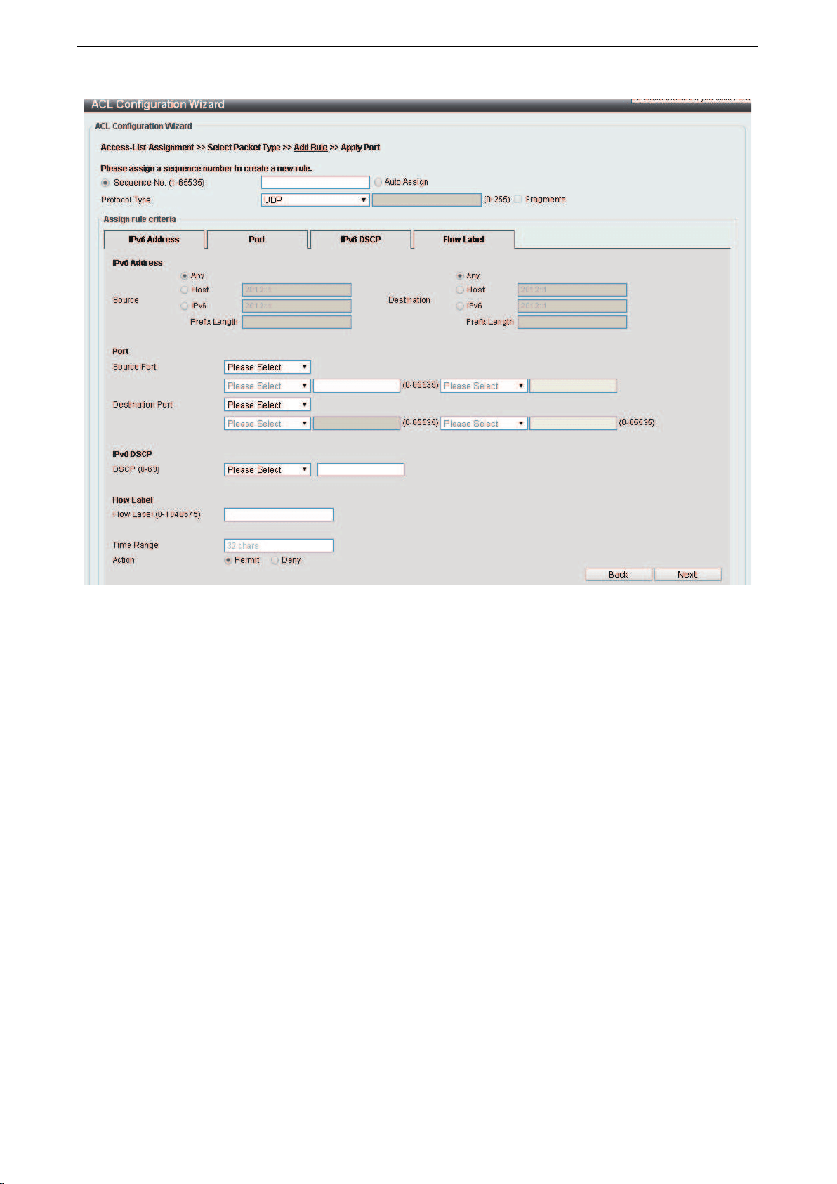
D-Link DXS-1210 Series User Manual
98
Figure 4.156 – ACL > ACL Configuration Wizard – Create IPv6 ACL-UDP
Source Port: Select the source port value.
Destination Port: Select the destination port value.
Source: Select the source information. The values are Any, Host and IP.
Destination: Select the destination information. The values are Any, Host and IP.
DSCP (0-63): Select the DSCP value. And the range is between 0 and 63.
Flow Label (0-1048575): Enter the flow label value. This value must be between 0 and 1048575.
Time Range: Enter the time range.
Action: Select the action for the rule. The values are Permit and Deny.
After selecting ICMP as the Protocol Type, click the IPv6 Address, ICMP, IPv6 DSCP and Flow Label tabs
to display the following page:
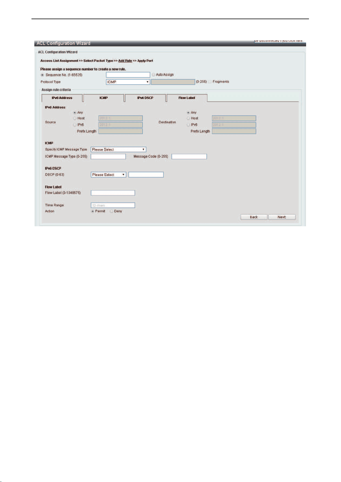
D-Link DXS-1210 Series User Manual
99
Figure 4.157– ACL > ACL Configuration Wizard – Create IPv6 ACL-ICMP
Source: Select the source information. The values are Any, Host and IP.
Destination: Select the destination information. The values are Any, Host and IP.
DSCP (0-63): Select the DSCP value. And the range is between 0 and 63.
Flow Label (0-1048575): Enter the flow label value. This value must be between 0 and 1048575.
Specify ICMP Message Type: Select the ICMP message type used.
ICMP Message Type (0-255): When the ICMP Message Type is not selected, enter the ICMP Message
Type numerical value. When the ICMP Message Type is selected, this numerical value will automatically be
entered.
Message Code (0-255): When the ICMP Message Type is not selected, enter the Message Code numerical
value. When the ICMP Message Type is selected, this numerical value will automatically be entered.
Time Range: Enter the time range.
Action: Select the action for the rule. The values are Permit and Deny.
After selecting Protocol ID as the Protocol Type, click the IPv6 Address, IPv6 DSCP and Flow Label tabs
to display the following page:
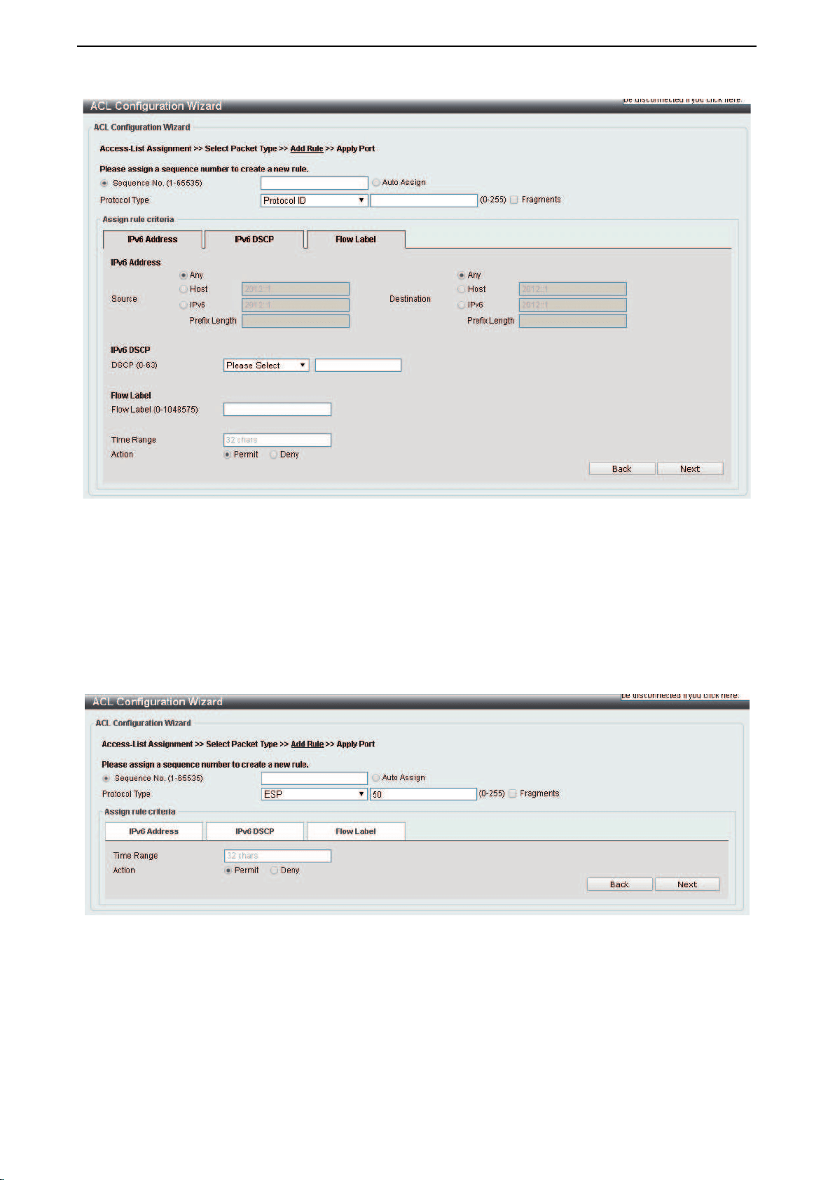
D-Link DXS-1210 Series User Manual
100
Figure 4.158 – ACL > ACL Configuration Wizard – Create IPv6 ACL-Protocol ID
Source: Select the source information. The values are Any, Host and IP.
Destination: Select the destination information. The values are Any, Host and IP.
DSCP (0-63): Enter the DSCP value. And the range is between 0 and 63.
Flow Label (0-1048575): Enter the flow label value. This value must be between 0 and 1048575.
Action: Select the action for the rule. The values are Permit and Deny.
After selecting ESP as the Protocol Type, click the IPv6 Address, IPv6 DSCP and Flow Label tabs to
display the following page:
Figure 4.159 – ACL > ACL Configuration Wizard – Create IPv6 ACL-ESP
Source: Select the source information. The values are Any, Host and IP.
Destination: Select the destination information. The values are Any, Host and IP.
DSCP (0-63): Enter the DSCP value. And the range is between 0 and 63.
Flow Label (0-1048575): Enter the flow label value. This value must be between 0 and 1048575.
Time Range: Enter the time range.
Action: Select the action for the rule. The values are Permit and Deny.
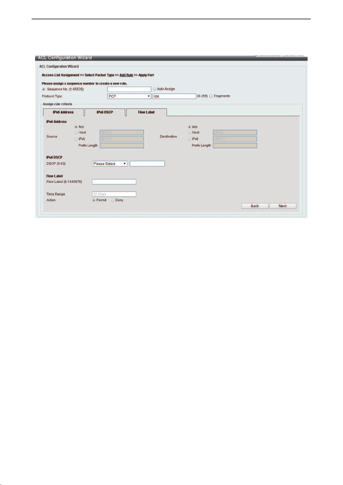
D-Link DXS-1210 Series User Manual
101
After selecting PCP as the Protocol Type, click the IPv6 Address, IPv6 DSCP and Flow Label tabs to
display the following page:
Figure 4.160 – ACL > ACL Configuration Wizard – Create IPv6 ACL-PCP
Source: Select the source information. The values are Any, Host and IP.
Destination: Select the destination information. The values are Any, Host and IP.
DSCP (0-63): Enter the DSCP value. And the range is between 0 and 63.
Flow Label (0-1048575): Enter the flow label value. This value must be between 0 and 1048575.
Time Range: Enter the time range.
Action: Select the action for the rule. The values are Permit and Deny.
After selecting SCTP as the Protocol Type, click the IPv6 Address, IPv6 DSCP and Flow Label tabs to
display the following page:
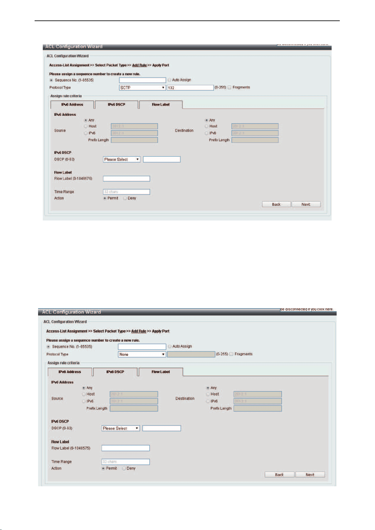
D-Link DXS-1210 Series User Manual
102
Figure 4.161 – ACL > ACL Configuration Wizard – Create IPv6 ACL-SCTP
Source: Select the source information. The values are Any, Host and IP.
Destination: Select the destination information. The values are Any, Host and IP.
DSCP (0-63): Enter the DSCP value. And the range is between 0 and 63.
Flow Label (0-1048575): Enter the flow label value. This value must be between 0 and 1048575.
Action: Select the action for the rule. The values are Permit and Deny.
After selecting the None as the Protocol Type, click the IPv6 Address, IPv6 DSCP and Flow Label tabs to
display the following page:
Figure 4.162 – ACL > ACL Configuration Wizard – Create IPv6 ACL-None
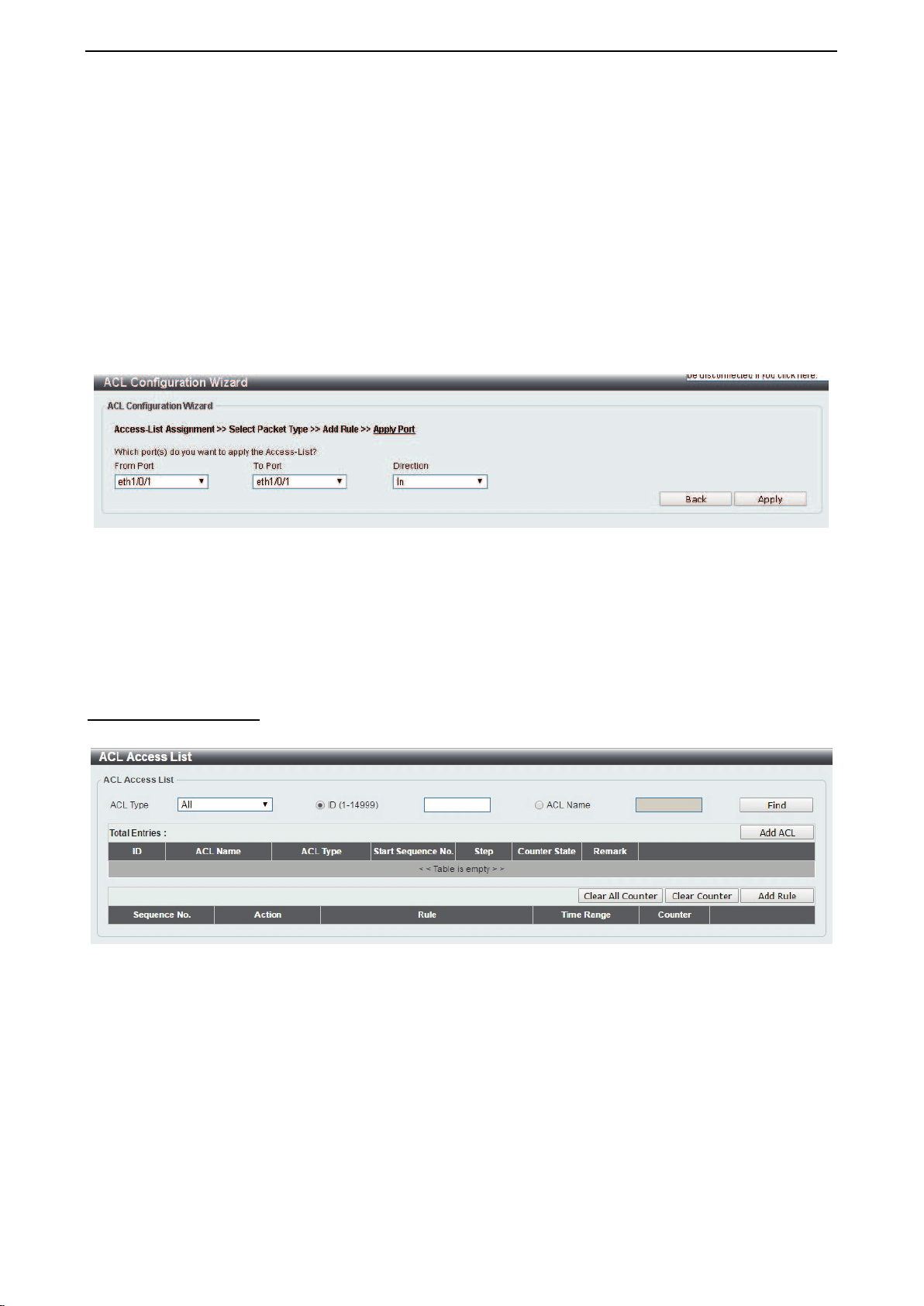
D-Link DXS-1210 Series User Manual
103
Source: Select the source information. The values are Any, Host and IP.
Destination: Select the destination information. The values are Any, Host and IP.
DSCP (0-63): Enter the DSCP value. And the range is between 0 and 63.
Flow Label (0-1048575): Enter the flow label value. This value must be between 0 and 1048575.
Time Range: Enter the time range.
Action: Select the action for the rule. The values are Permit and Deny.
Click the Back button to return to the previous window.
Click the Next button to continue.
After clicking the Next button, the following page will appear.
Figure 4.163 – ACL > ACL Configuration Wizard – Create IPv6 ACL-Next
From Port / To Port: Select the range of ports to be configured.
Direction: Select either In or Out.
Click the Back button to return to the previous window.
Click the Apply button to save your settings.
ACL > ACL Access List
The ACL Access List page allows you to view and configure the access list settings.
Figure 4.164 – ACL > ACL Access List
ACL Type: Select the ACL profile type to find. Options to choose from are All, IP ACL, IPv6 ACL, MAC
ACL, and Expert ACL.
ID (1-14999): Select and enter ACL ID. The range is between 1 and 14999.
ACL Name: Select and enter ACL name. The name can be up to 32 characters long.
Click the Find button to locate a specific entry based on the information entered.
Click the Add ACL button to create a new ACL profile.
Click the Clear All Counter button to clear all the counter information displayed.
Click the Clear Counter button to clear the counter information for the rule displayed.
Click the Add Rule button to create an ACL rule for the ACL profile selected.
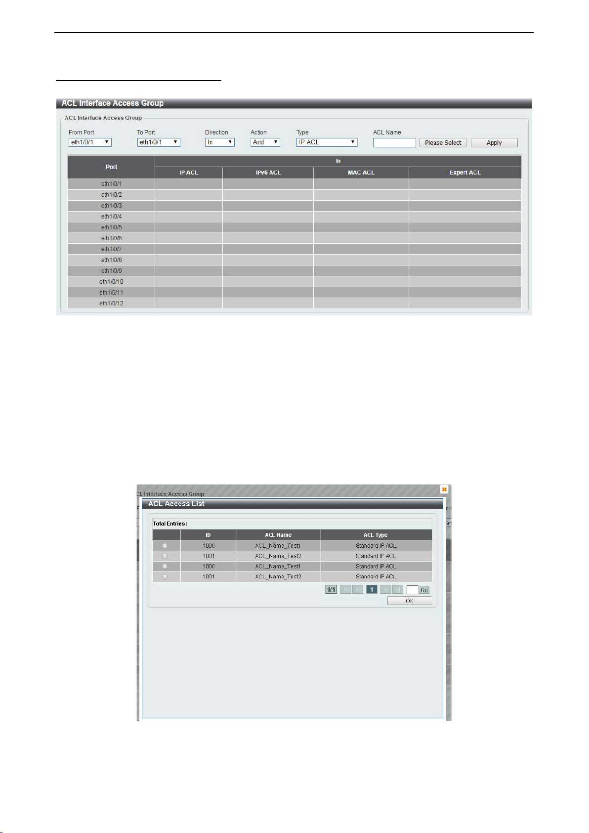
D-Link DXS-1210 Series User Manual
104
ACL > ACL Interface Access Group
The ACL Interface Access Group page allows you to view and configure the interface access group settings.
Figure 4.165 – ACL > ACL Interface Access Group
From Port / To Port: Select the range of ports to be configured.
Direction: Select the direction.
Action: Select the action to be Add or Delete.
ACL Type: Select the ACL profile type to find. Options to choose from are All, IP ACL, IPv6 ACL, MAC
ACL, and Expert ACL.
ACL Name: Enter ACL name. The name can be up to 32 characters long.
Click the Apply button to save your settings.
After clicking the Please Select button, the following page will appear.
Figure 4.166 – ACL > ACL Interface Access Group - Select
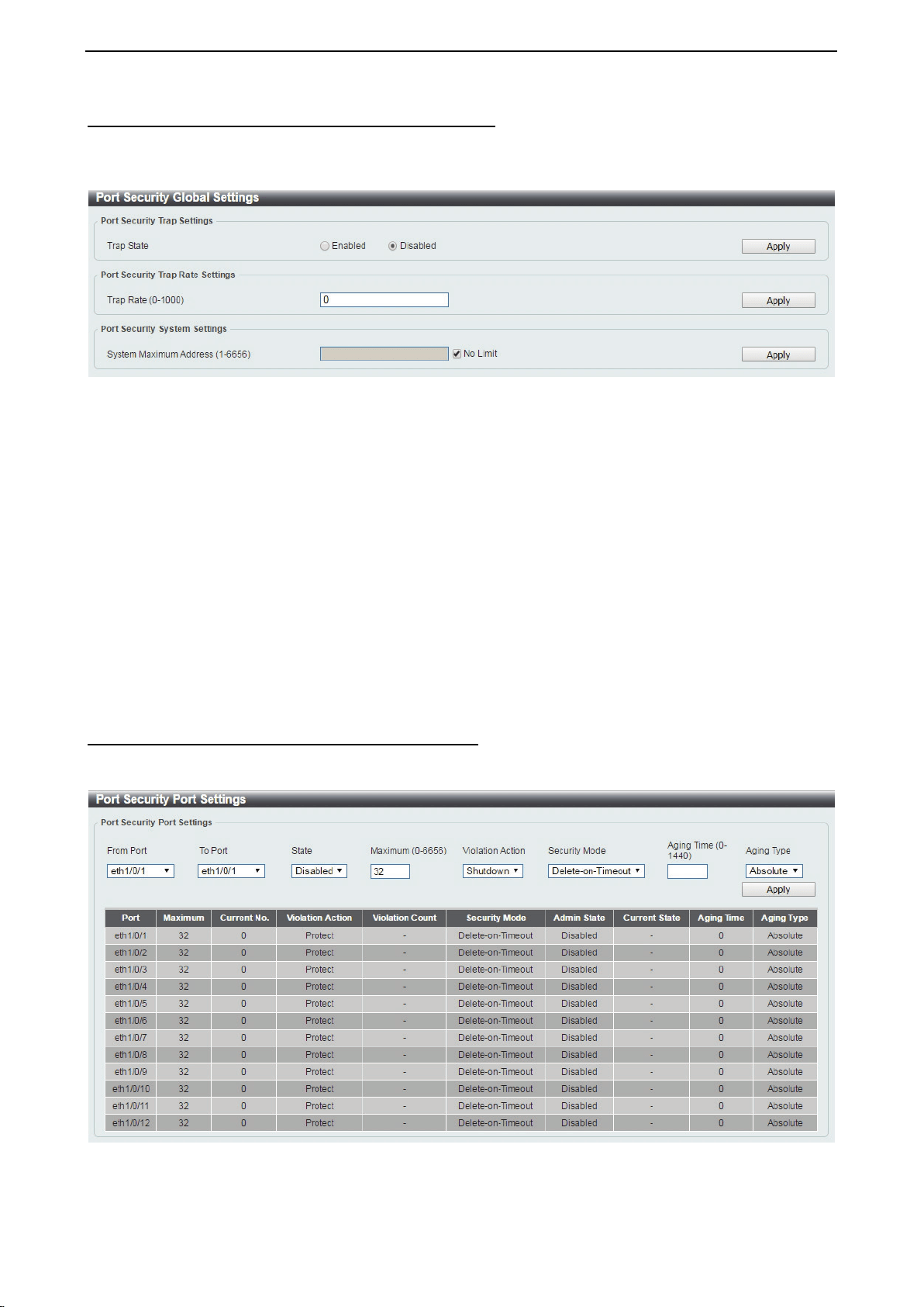
D-Link DXS-1210 Series User Manual
105
Security > Port Security > Port Security Global Settings
The Port Security Global Settings page allows you to view and configure the global port security settings.
Port Security is a feature that prevents unauthorized computers (with source MAC addresses) unknown to
the Switch from connection and gaining access to the network.
Figure 4.167 – Security > Port Security > Port Security Global Settings
Trap Security Trap Settings:
Trap State: Select to enable or disable the port security trap of the Switch.
Click the Apply button to save your settings.
Port Security Trap Rate Settings:
Trap Rate (0-1000): Enter the number of traps per second. The range is from 0 to 1000.
Click the Apply button to save your settings.
Port Security System Settings:
System Maximum Address (1-6656): Enter the maximum number of secure MAC addresses allowed. If not
specified, the default value is No Limit. The valid range is from 1 to 6656. Tick the No Limit checkbox to
allow the maximum number of secure MAC addresses.
Click the Apply button to save your settings.
Security > Port Security > Port Security Port Settings
The Port Security Port Settings page allows you to view and configure the port security port settings of the
Switch.
Figure 4.168 – Security > Port Security > Port Security Port Settings
From Port / To Port: Select the range of ports to be configured.
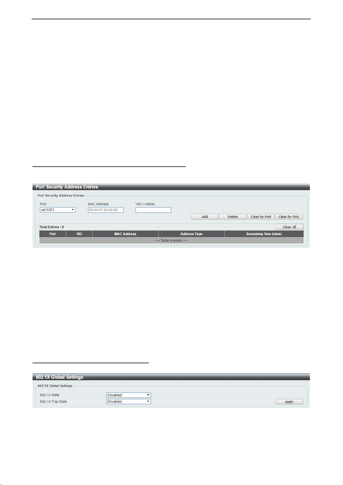
D-Link DXS-1210 Series User Manual
106
State: Select to enable or disable the port security state of specified ports.
Maximum (1-6556): Enter the maximum number of secure MAC addresses that will be allowed on the
specified ports. The value is between 1 and 6656.
Violation Action: Select the violation action that will be taken. The values are Protect, Restrict, and
Security Mode: Select the security mode option. The values are Permanent and Delete-on-Timeout. If you
select Permanent, the MAC addresses that have been learned by the Switch will not be purged unless you
manually delete them. If you select Delete-on-Timeout, all learned MAC addresses will be purged when an
entry is aged out or when you manually delete them.
Aging Time (0-1440): Enter the aging time for auto-learned dynamic addresses on the specified ports.
Aging Type: Select the aging type. The values are Absolute and Inactivity. Select Absolute so that all the
dynamic addresses on this port age out exactly after the time specified and are removed from the secure
address list. This is the default option. Select Inactivity so that the dynamic addresses on this port age out
only if there is no traffic from the addresses for the specified time period.
Click the Apply button to save your settings.
Security > Port Security > Port Security Address Entries
The Port Security Address Entries page allows you to view, clear and configure the port security address
entries.
Figure 4.169 – Security > Port Security > Port Security Address Entries
Port: Select the port to be configured.
MAC Address: Enter the MAC address for the specified port.
VID (1-4094): Enter the VLAN ID. The range is between 1 and 4094.
Click the Add button to add a new entry based on the information entered.
Click the Delete button to remove a new entry based on the information entered.
Click the Clear by Port button to clear the information based on the port selected.
Click the Clear by MAC button to clear the information based on the MAC address entered.
Click the Clear All button to clear all the information in this table.
Enter a page number and click the Go button to navigate to a specific page when multiple pages exist.
Security > 802.1X > 802.1X Global Settings
The 802.1X Global Settings page allows you to configure the 802.1X feature.
Figure 4.170 – Security > 802.1X > 802.1X Global Settings
802.1X State: Specify to enable or disable the 802.1X state.
802.1X Trap State: Specify to enable or disable the 802.1X trap state.
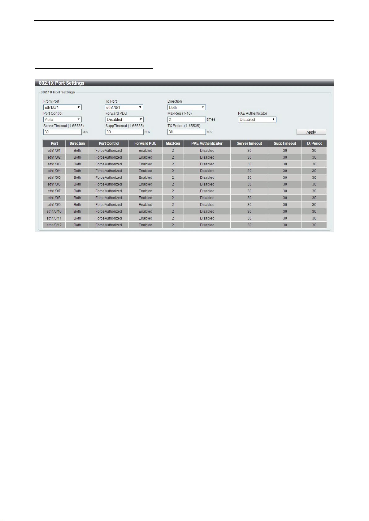
D-Link DXS-1210 Series User Manual
107
Click the Apply button to save your settings.
Security > 802.1X > 802.1X Port Settings
The 802.1X Port Settings page allow you to configure the port settings.
Figure 4.171 – Security > 802.1X > 802.1X Port Settings
From Port / To Port: Select the range of ports to be configured.
Direction: Sets the administratively-controlled direction on the port. The possible field values are:
Both: Specify the control is exerted over both incoming and outgoing traffic through the controlled
port selected in the first field.
In: Disables the support in the present firmware release.
Port Control: This allows user to control the port authorization state.
Select ForceAuthorized to disable 802.1X and cause the port to transition to the authorized state
without any authentication exchange required. This means the port transmits and receives normal
traffic without 802.1X-based authentication of the client.
If ForceUnauthorized is selected, the port will remain in the unauthorized state, ignoring all
attempts by the client to authenticate. The Switch cannot provide authentication services to the client
through the interface.
If Auto is selected, it will enable 802.1X and cause the port to begin in the unauthorized state,
allowing only EAPOL frames to be sent and received through the port. The authentication process
begins when the link state, transitions from down to up, or when an EAPOL-start frame is received.
The Switch then requests the identity of the client and begins relaying authentication messages
between the client and the authentication server. The default setting is Auto.
Forward PDU: Select to enable or disable the forward PDU option here.
MaxReq(1-10): This parameter specifies the maximum number of times that the switch retransmits an EAP
request (md5-challenge) to the client before it times out the authentication session. Default is 2 times.
PAE Authenticator: Select to enable or disable the Port Access Entity (PAE) authenticator option here. This
option configures a specific port as an IEEE 802.1X PAE authenticator.
ServerTimeout(1-65535): Sets the amount of time the switch waits for a response from the client before
resending the response to the authentication server. The default is 30 seconds.
SuppTimeout(1-65535): This value determines timeout conditions in the exchanges between the
authenticator and the client. The default is 30 seconds.
TX Peiord(1-65535): This sets the TxPeriod of time for the authenticator PAE state machine. This value
determines the period of an EAP Request/Identity packet transmitted to the client. The default is 30 seconds.
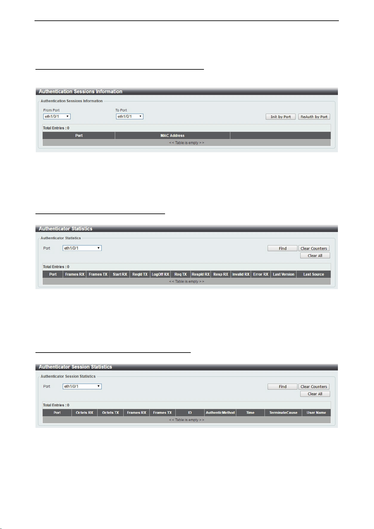
D-Link DXS-1210 Series User Manual
108
Click the Apply button to save your settings.
Security > 802.1X > Authentication Sessions Information
The Authentication Sessions Information page is used to view and configure the authentication session
information.
Figure 4.172 – Security > 802.1X > Authentication Sessions Information
From Port / To Port: Select the port to be queried.
Click the Init by Port button to initiate the session information based on the selections made.
Click the ReAuth by Port button to re-authenticate the session information based on the selections made.
Security > 802.1X > Authenticator Statistics
The Authenticator Statistics page is used to view and clear the authenticator statistics.
Figure 4.173 – Security > 802.1X > Authenticator Statistics
Port: Select the port to be queried.
Click the Clear Counters button to clear the counter information based on the selections made.
Click the Clear All button to clear all the information in this table.
Security > 802.1X > Authenticator Session Statistics
The Authenticator Session Statistics is used to view and clear the authenticator session statistics.
Figure 4.174 – Security > 802.1X > Authenticator Sessions Statistics
Port: Select the port to be queried.
Click the Find button to locate a specific entry based on the information entered.
Click the Clear Counters button to clear the counter information based on the selections made.
Click the Clear All button to clear all the information in this table.
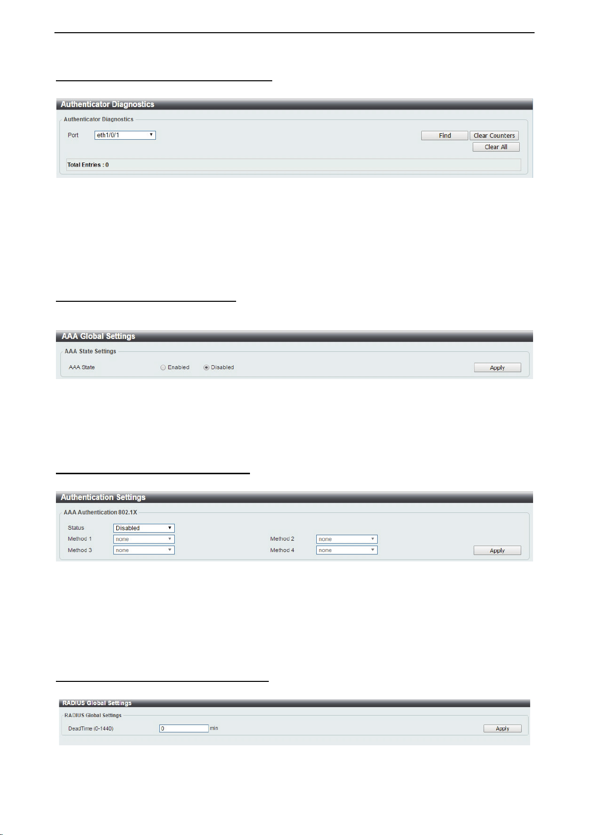
D-Link DXS-1210 Series User Manual
109
Security > 802.1X > Authenticator Diagnostics
The authenticator Diagnostics is used to view and clear the authenticator diagnostics information.
Figure 4.175 – Security > 802.1X > Authenticator Diagnostics
Port: Select the port to be queried.
Click the Find button to locate a specific entry based on the information entered.
Click the Clear Counters button to clear the counter information based on the selections made.
Click the Clear All button to clear all the information in this table.
Security > AAA > AAA Global Settings
The AAA Global Settings is used to enable or disable the global Authentication, Authorization, and
Accounting (AAA) state.
Figure 4.176 – Security > AAA > AAA Global Settings
AAA State: Specify to enable or disable the global AAA state.
Click the Apply button to accept the changes made.
Security > AAA > Authentication Settings
The Authentication Settings is used to view and configure the application authentication settings.
Figure 4.177 – Security > AAA > AAA Authentication Settings
Status: Select to enable or disable the AAA 802.1X authentication state.
Method 1 / Method 2 / Method 3 / Method 4: Select the method lists that will be used for this configuration.
Options to choose from are local, group and Radius.
Click the Apply button to accept the changes made.
Security > RADIUS > RADIUS Global Settings
The RADIUS Global Settings page allows you to view and configure the RADIUS global settings.
Figure 4.178 – Security > RADIUS > RADIUS Global Settings
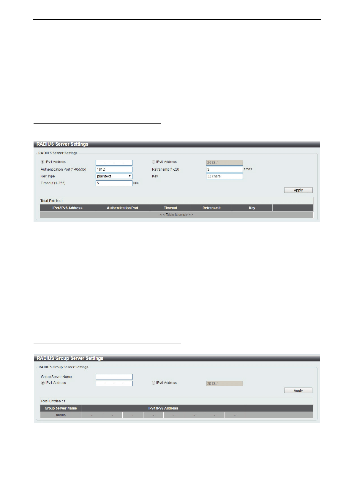
D-Link DXS-1210 Series User Manual
110
Dead Time: Enter the dead time value here. This value must be between 1 and 1440 minutes. By default,
this value is 0 minutes. When this option is 0, the unresponsive server will not be marked as dead. This
setting can be used to improve the authentication processing time by setting the dead time to skip the
unresponsive server host entries. When the system performs authentication with the authentication server, it
attempts one server at a time. If the attempted server does not respond, the system will attempt the next
server. When the system finds a server does not respond, it will mark the server as down, start a dead time
timer, and skip them in authentication of the following requests until expiration of the dead time.
Click the Apply button to accept the changes made.
Security > RADIUS > RADIUS Server Settings
The RADIUS feature of the Switch allows the user to facilitate centralized user administration and provide
protection against hacking attacks.
Figure 4.179 – Security > RADIUS > RADIUS Server Settings
Click the IPv4 Address or IPv6 Address and enter the IP address to be configured.
Authentication Port (1-65535): Enter the authentication port number used here. This value must be
between 0 and 65535. By default, this value is 1812. If no authentication is used, use the value 0.
Retransmit (1-20): Enter the accounting value used here. This value must be between 0 and 20. By default,
the value is 3. To disable this option, enter the value 0.
Key Type: Select the key type that will be used. Options to choose from are Plain Text and Encrypted.
Key: Enter the key used to communicate with the RADIUS server. This key can be up to 32 characters long.
Timeout (1-255): Enter the timeout value. This value must be between 1 and 255 seconds. By default, this
value is 5 seconds.
Click the Apply button to save your settings.
Security > RADIUS > RADIUS Group Server Settings
The RADIUS Group Server Settings page is used to view and configure the RADIUS group server setting.
Figure 4.180 – Security > RADIUS > RADIUS Group Server Settings
Group Server name: Enter the RADIUS group server’s name. This name can be up to 15 characters long.
IP Address: Enter the group server’s IPv4 address.
IPv6 Address: Enter the group server’s IPv6 address.
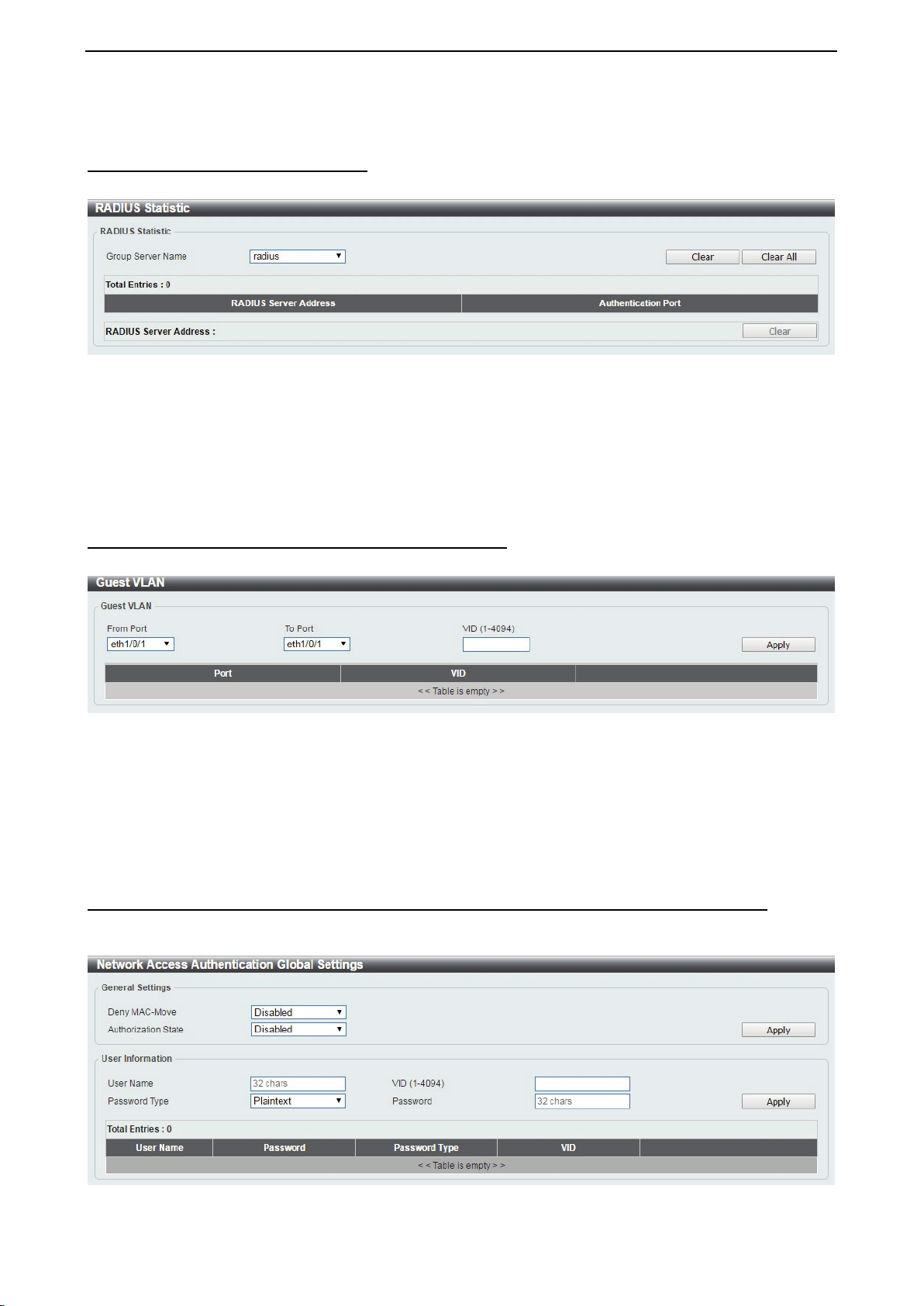
D-Link DXS-1210 Series User Manual
111
Click the Apply button to save your settings.
Security > RADIUS > RADIUS Statistic
The RADIUS Statistic page is used to view and clear the RADIUS statistics information.
Figure 4.181 – Security > RADIUS > RADIUS Statistic
Group Server Name: Select the RADIUS group server name from this list here.
Click the Clear button to clear the information based on the selections made.
Click the Clear All button to clear all the information in this table. Enter a page number and click the Go
button to navigate to a specific page when multiple pages exist.
Security > Network Access Authentication > Guest VLAN
The Guest VLAN page is used to view and configure the network access authentication guest VLAN settings.
Figure 4.182 – Security > Network Access Authentication > Guest VLAN
From Port / To Port: Select the appropriate port range used for the configuration here.
VID (1-4094): Enter the VLAN ID used here. This value must be between 1 and 4094.
Click the Apply button to accept the changes made.
Click the Delete button to remove the specified entry.
Security > Network Access Authentication > Network Access Authentication Global Settings
The Network Access Authentication global Settings page is used to view and configure the network access
authentication global settings.
Figure 4.183 – Security > Network Access Authentication > Network Access Authentication Global Settings
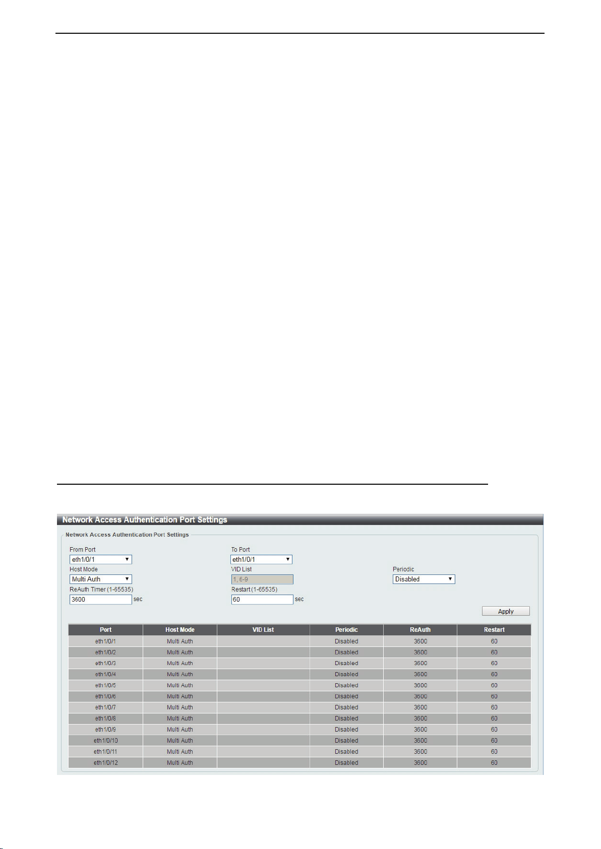
D-Link DXS-1210 Series User Manual
112
General Settings:
Deny MAC–Move: Select to enable or disable the Deny MAC-Move feature here. This option controls
whether authenticated hosts can move between switch ports and whether a host configured for multi-
authenticate mode can move to another port.
If a station is allowed to move, it may either need to be re-authenticated or can move without re-
authentication, depending on the configuration of the port it is moving to. If the new port has the same
authentication configuration as the original port, then re-authentication is not required. If the port has different
authentication configuration, then re-authentication is needed.
If this feature is disabled and an authenticated host moves to another port, then this is treated as a violation
error.
Authorization State: Select to enable or disable the Authorized State. This is used to enable or disable the
acceptance of an authorized configuration and apply this to the host or port. When authorization state is
enabled, the attributes assigned by the RADIUS server, for example: VLAN, 802.1p default priority,
bandwidth, and ACL will be accepted.
The bandwidth and ACL attributes are assigned on a per-port basis. If the Network Access Authentication
Port Settings Host Mode is set to Multi Auth, the VLAN and 802.1p attributes are assigned on a per-host
basis.
Click the Apply button to accept the changes made.
User Information:
User Name: Enter the user name used here. This name can be up to 32 characters long.
VID (1-4094): Enter the VLAN ID used here.
Password Type: Select the password type option here. Options to choose from are Plain Text and
Encrypted.
Password: Enter the password used here.
Click the Apply button to accept the changes made.
Click the Delete button to remove the specified entry.
Security > Network Access Authentication > Network Access Authentication Port Settings
The Network Access Authentication Port Settings page is used to view and configure the network access
authentication port settings.
Figure 4.184 – Security > Network Access Authentication > Network Access Authentication Port Settings
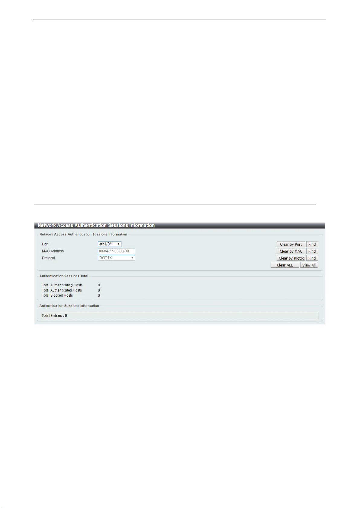
D-Link DXS-1210 Series User Manual
113
From Port / To Port: Select the range of ports to be configured.
Host Mode: Select the host mode option that will be associated with the selected port(s) here. Options to
choose from are Multi Host and Multi Auth. If the port is operated in the multi-host mode, and if one of the
hosts is authenticated, then all other hosts are allowed to access the port. According to 802.1X
authentication, if the re-authentication fails or the authenticated user logs off, the port will be blocked for a
specified period. The port restores the processing of EAPOL packets after the specified period. If the port is
operated in the multi-authenticated mode, then each host needs to be authenticated individually to access
the port. A host is represented by its MAC address and is only hosts that can be authenticated are allowed
network access.
VID List: After selecting the Multi Auth option as the host mode, the following parameter is available. Enter
the VLAN ID to be enabled for authentication. After the client is authenticated, the client will not be re-
authenticated when present on other VLANs. When a port’s authentication mode is changed to Multi Host,
the previous authentication VLAN(s) on this port will be cleared..
ReAuth Timer (1-65535): Enter the re-authentication timer value. This value must be between 1 and 65535
seconds. By default, this value is 3600 seconds.
Restart (1-65535): Enter the restart time value used. This value must be between 1 and 65535 seconds.
Click the Apply button to accept the changes made.
Security > Network Access Authentication > Network Access Authentication Sessions Information
The Network Access Authentication Sessions Information is used to view and clear the network access
authentication session information.
Figure 4.185 – Security > Network Access Authentication > Network Access Authentication Sessions Information
Port: Select the port to be queried.
MAC Address: Enter the MAC address of the client.
Protocol: Select the authentication protocol used. Options to choose from are MAC, WAC, and DOT1X.
Clear by Port: Click the Clear by Port button to clear the authentication session information by selected port.
Clear by MAC: Click the Clear by MAC button to clear the authentication session information by selected
MAC address.
Clear by Protocol: Click the Clear by Protocol button to clear the authentication session information by
selected protocol.
Clear ALL: Click the Clear ALL button to clear all authentication session information.
Click the Find button to locate a specific entry based on the information entered.
Click the View All button to locate and display all the entries.
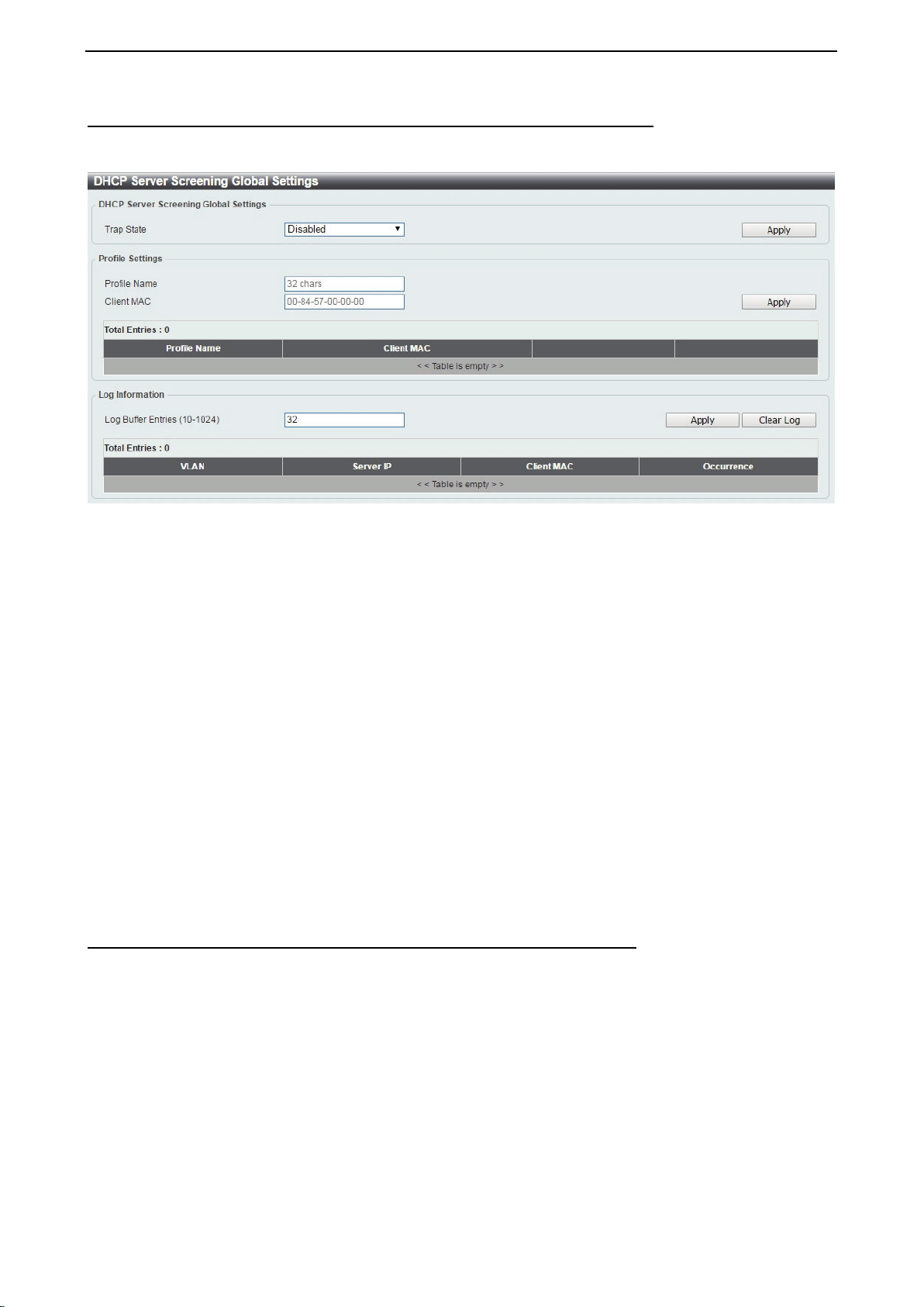
D-Link DXS-1210 Series User Manual
114
Security > DHCP Server Screening > DHCP Server Screening Global Settings
DHCP Server Screening function allows you to restrict an illegal DHCP server by discarding DHCP packets
from distrusted ports.
Figure 4.186 – Security > DHCP Server Screening > DHCP Server Screening Global Settings
DHCP Server Screening Global Settings:
Trap State: Select to enable or disable the trap state.
Click the Apply button to save your settings.
Profile Settings:
Profile Name: Enter the profile name.
Client MAC: Enter the MAC address.
Click the Delete button to remove the specified entry of the table.
Click the Delete Profile button to remove the specified profile.
Click the Apply button to save your settings.
Enter a page number and click the Go button to navigate to a specific page when multiple pages exist.
Log Information:
Log Buffer Entries (10-1024): Enter the logged buffer entries. The value is between 10 and 1024.
Click the Apply button to save your settings.
Click the Clear Log button to clear the log.
Security > DHCP Server Screening > DHCP Server Screening Port Settings
The DHCP Server Screening Port Settings page allows you to view and configure DHCP server screening
ports.
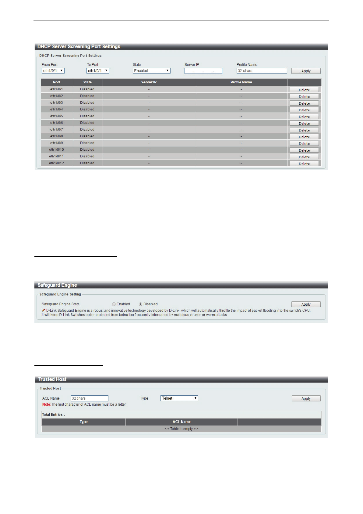
D-Link DXS-1210 Series User Manual
115
Figure 4.187 – Security > DHCP Server Screening > DHCP Server Screening Port Settings
From Port / To Port: Select the range of ports to be configured.
State: Select to enable or disable the DHCP server screening port state.
Profile Name: Enter the profile name of specified ports.
Server IP: Select IPv4 Address or IPv6 Address and enter the DHCP server IP.
Click the Apply button to save your settings.
Security > Safeguard Engine
D-Link’s Safeguard Engine is a robust and innovative technology that automatically throttles the impact of
packet flooding into the switch's CPU. This function helps to protect the the Switch from being interrupted by
malicious viruses or worm attacks. This option is enabled by default.
Figure 4.188 – Security > Safeguard Engine
Click the Apply button to save your settings.
Security > Trusted Host
The Trusted Host page allows you to view and configure the trusted host settings.
Figure 4.189 Security > Trusted Host
ACL Name: Specify the ACL name. The name can be up to 32 characters long.
Type: Specify the trusted host type. The options are Telnet, Ping, HTTP and HTTPS.
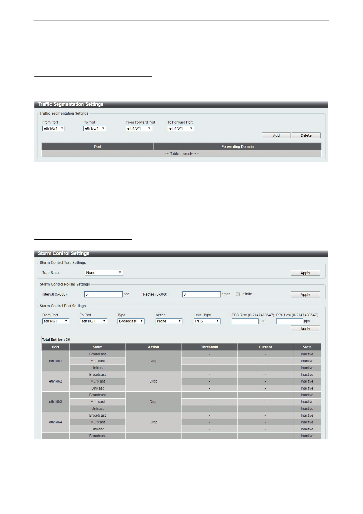
D-Link DXS-1210 Series User Manual
116
Click the Apply button to save your settings.
Security > Traffic Segmentation Settings
This feature provides administrators to limit traffic flow from a single port to a group of ports on a single
Switch. This method of segmenting the flow of traffic is similar to using VLANs to limit traffic, but is more
restrictive.
Figure 4.190 – Security > Traffic Segmentation Settings
From Port / To Port: Select the range of ports to be configured.
From Forward Port / To Forward Port: Select the range of forward ports to be configured.
Click the Add button to add a new entry.
Click the Delete button to remove an entry based on the information entered.
Security > Storm Control Settings
The Storm Control Settings page allows you to view and configure the storm control settings.
Figure 4.191 – Security > Storm Control Settings-PPS
Trap State: Select the storm control trap state. The options are None, Storm Occur, Storm Clear, and
Both. When None is selected, no traps will be sent. When Storm Occur is selected, a trap notification will
be sent when a storm event is detected. When Storm Clear is selected, a trap notification will be sent when
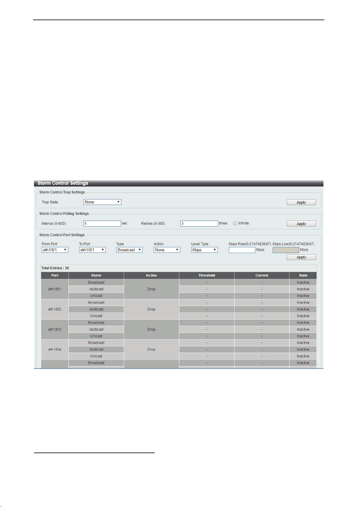
D-Link DXS-1210 Series User Manual
117
a storm event is cleared.
Click the Apply button to save your settings.
Storm Control Polling Settings:
Interval (1-300): Enter the interval value. The range is from 1 to 300.
Retries (0-360): Enter the retry value. The range is from 0 to 360.
Click the Apply button to save your settings.
Storm Control Port Settings:
From Port / To Port: Select the range of ports to be configured.
Type: Select the type of storm attack. The values are Broadcast, Multicast, and Unicast.
Action: Select the action for the specified ports. The values are None, Shutdown and Drop.
Level Type: Select PPS or Kbps as the level type. When PPS is selected, the PPS Rise & PPS Low fields
will be shown.
PPS Rise (1-2147483647): Enter the rise packets per second value. The value is from 1 to 2147483647.
PPS Low (1-2147483647): Enter the low packets per second value. The value is from 1 to 2147483647.
Figure 4.192 – Security > Storm Control Settings-Kbps
When Kbps is select as the level type, the Kbps Rise field will be shown, and Kbps Low will be disabled.
The Current column in the Storm Control information table will be empty.
Kbps Rise (1-2147483647): Enter the rise packets per second value. The value is from 1 to 2147483647.
Kbps Low (1-2147483647): The field is un-configured.
Click Apply for the settings to take effect.
Security > DoS Attack Prevention Settings
The DoS Attack Prevention Settings page allows you to view and configure the Denial-of-Service (DoS)
attack prevention settings.
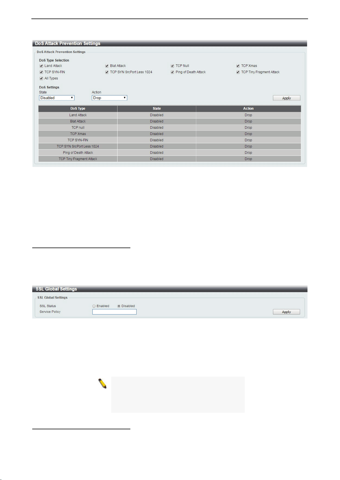
D-Link DXS-1210 Series User Manual
118
Figure 4.193 – Security > DoS Attack Prevention Settings
DoS Attack Prevention Settings:
DoS Type Selection: Tick the DoS type to be prevented.
State: Select to enable or disable the DoS attack prevention state.
Action: Select the action for the DoS attack.
Click the Apply button to save your settings.
Security > SSL > SSL Global Setting
Secure Sockets Layer (SSL) is a security feature that provides a secure communication path between the
management PC and the Switch Web UI by using authentication, digital signatures and encryption. These
security functions are implemented by Ciphersuite, a security string that determines the cryptographic
parameters, encryption algorithms and key sizes.
This page allows you to configure the SSL global state settings.
Figure 4.194 – Security > SSL > SSL Settings
SSL Global Settings:
SSL Status: Select to enable or disable the SSL feature’s global status.
Service Policy: Enter service policy name.
Click Apply for the settings to take effect.
NOTE: When SSL is enabled, it will take longer to
open a web page due to
the extra processing
required for encryption. After saving, please wait
about 10 seconds for the system summery page
to load.
Security > SSL > SSL Service Policy
The SSL Service Policy page allows you to view and configure the SSL service policy settings.
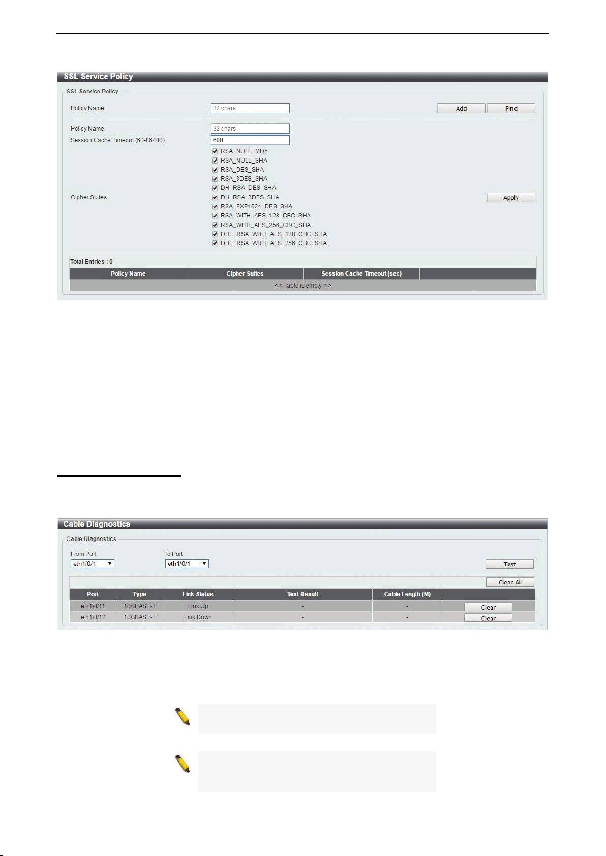
D-Link DXS-1210 Series User Manual
119
Figure 4.195 – Security > SSL > SSL Service Policy
Policy Name: Enter a policy name for SSL.
Click the Add button to save your settings.
Click the Find button to locate a specific entry based on the information entered.
Session Cache Timeout (60-86400): Enter the session cache timeout value. The value is between 60 and
86400 seconds.
Cipher Suites: Select the cipher suites that will be associated with this profile.
Click the Apply button to save your settings.
OAM > Cable Diagnostics
The Cable Diagnostics page is designed primarily for administrators and customer service representatives to
examine the copper cable quality. It determines the type of cable errors in the cable. Select the range of
ports and then click the Test button to start the diagnosis.
Figure 4.196 – OAM > Cable Diagnostic
Click the Clear button to clear all the information for the specific port.
Click the Clear All button to clear all the information in this table.
NOTE: Cable length detection is available on
Gigabit ports only.
NOTE: Please be sure that the
Power Saving
feature is disabled before enabling the Cable
Diagnostics function.
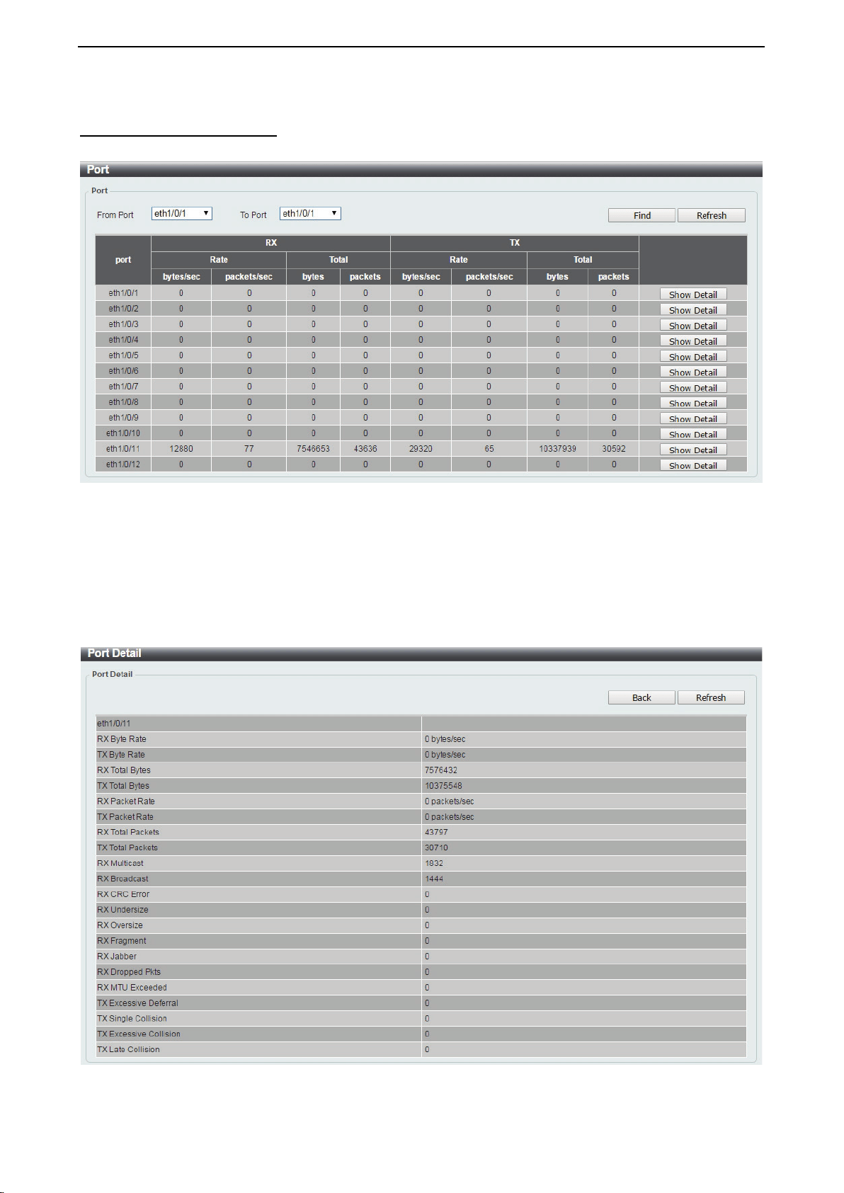
D-Link DXS-1210 Series User Manual
120
Monitoring > Statistics > Port
This page allows you to display the port traffic statistics.
Figure 4.197 – Monitoring > Statistics > Port
From Port / To Port: Select the range of ports to be configured.
Click the Find button to locate a specific entry based on the information entered.
Click the Refresh button to refresh the display table.
After clicking the Show Detail button, the following page will appear.
Figure 4.198 – Monitoring > Statistics > Port – Show Detail
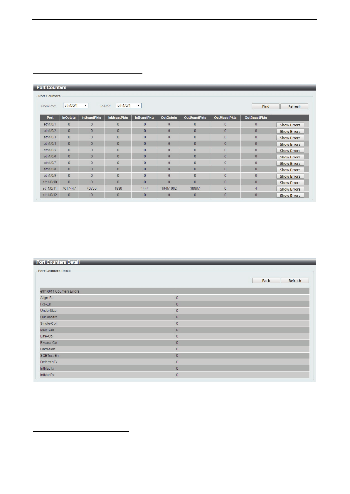
D-Link DXS-1210 Series User Manual
121
Click the Back button to return to the previous window.
Click the Refresh button to refresh the display table.
Monitoring > Statistics > Port Counters
The Port Counters page allows you to display port counter statistics.
Figure 4.199 – Monitoring > Statistics > Port Counters
From Port / To Port: Select the range of ports to be viewed.
Click the Find button to locate a specific entry based on the information entered.
Click the Refresh button to refresh the display table.
Click the Show Errors button to see all error counters of the specific port.
After clicking the Show Errors button, the following page will appear.
Figure 4.200 – Monitoring > Statistics > Port Counters – Show Errors
Click the Back button to return to the previous window.
Click the Refresh button to refresh the display table.
Monitoring > Statistics > Counters
The Counters page allows you to display all port counters, and clear the port counters of the specified or all
ports.

D-Link DXS-1210 Series User Manual
122
Figure 4.201 – Monitoring > Statistics > Counters
From Port / To Port: Select the range of ports to be viewed.
Click the Find button to locate a specific entry based on the information entered.
Click the Refresh button to refresh the display table.
Click the Clear button to clear all the information for the specific ports.
Click the Clear All button to clear all the information in this table.
Click the Show Detail button to see the detail information of the specific port.
After clicking the Show Detail button, the following page will appear.
Figure 4.202 – Monitoring > Statistics > Counters – Show Detail
Click the Back button to return to the previous window.
Click the Refresh button to refresh the display table.
Monitoring > Mirror Settings
The Mirror Settings page allows you to view and configure the port mirroring feature.
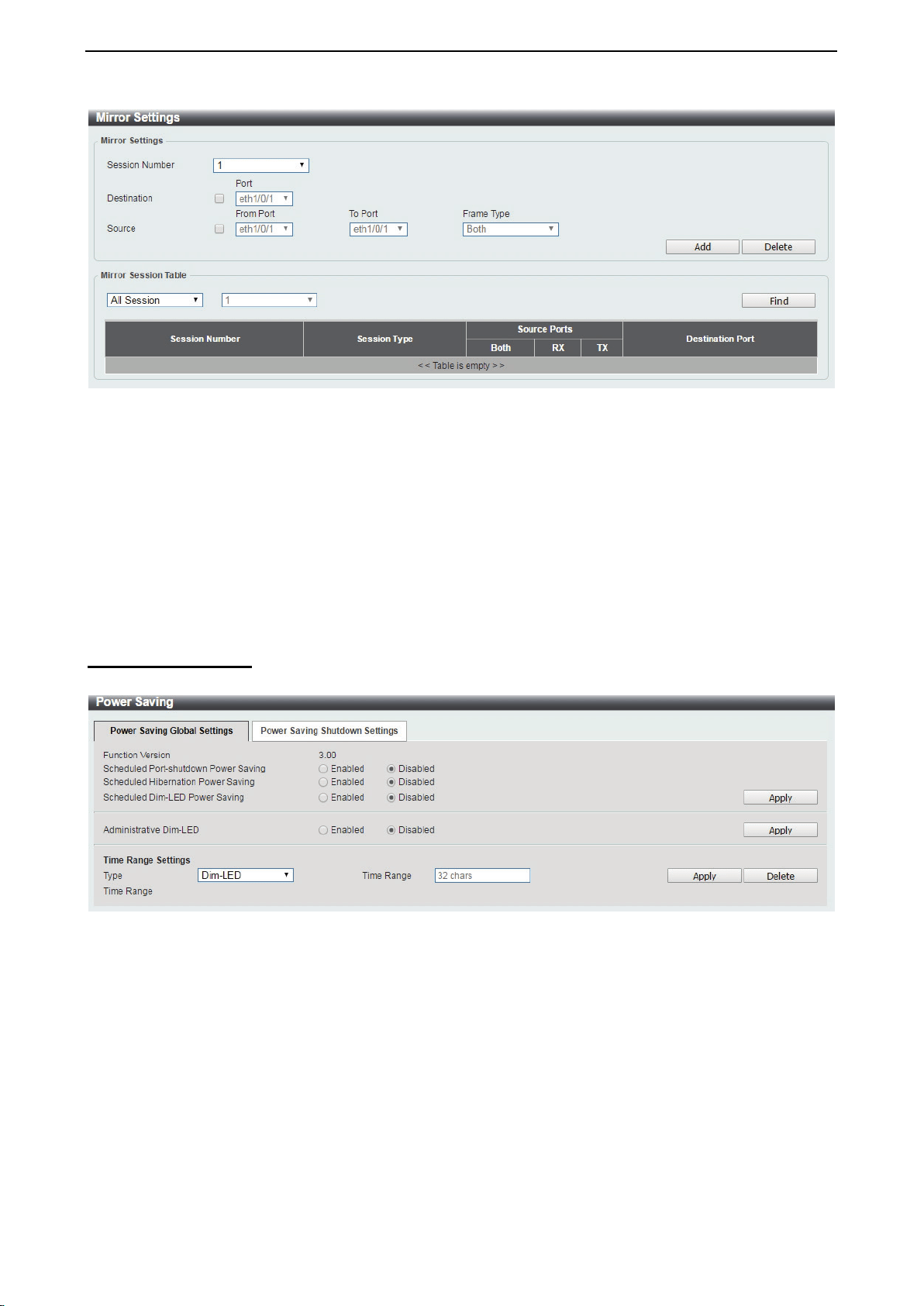
D-Link DXS-1210 Series User Manual
123
Figure 4.203 – Monitoring > Mirror Settings
Session Number: Select the mirror session number for the entry.
Destination: Select the destination port for mirror settings.
Source: Select the range of ports to be the source port and Frame Type to be mirrored.
Click the Add button to add the newly configured mirror entry based on the information entered.
Click the Delete button to delete an existing mirror entry based on the information entered.
Mirror Session Table: Select the Mirror Session Type to be displayed.
Click the Find button to locate a specific entry based on the information entered.
Green > Power Saving
The Power Saving page allows you to configure the power saving settings of the Switch.
Figure 4.204 – Green > Power Saving
Scheduled Port-shutdown Power Saving: Select to enable or disable the scheduled port shutdown power
saving feature.
Scheduled Hibernation Power Saving: Select to enable or disable the scheduled hibernation power saving
feature. When this option is enabled, the system will enter into the hibernation mode based on the specified
time range. When the system enters the hibernation mode, the switch will go into a low power state and idle.
It will shut down all the ports and LEDs and all network function will be disabled. If the Switch is an endpoint
type Power Sourcing Equipment (PSE), the Switch will not provide power to the port.
Scheduled Dim-LED Power Saving: Select to enable or disable applying the power saving by scheduled
dimming of the Switch LEDs.
Administrative Dim-LED: Select to enable or disable the port LED dimming function.
Type: Select the type of power saving. Options to choose from are Dim-LED and Hibernation.
Time Range: Select the name of the time range to associate with the power saving type.
Click the Apply button to save your settings for each individual section.
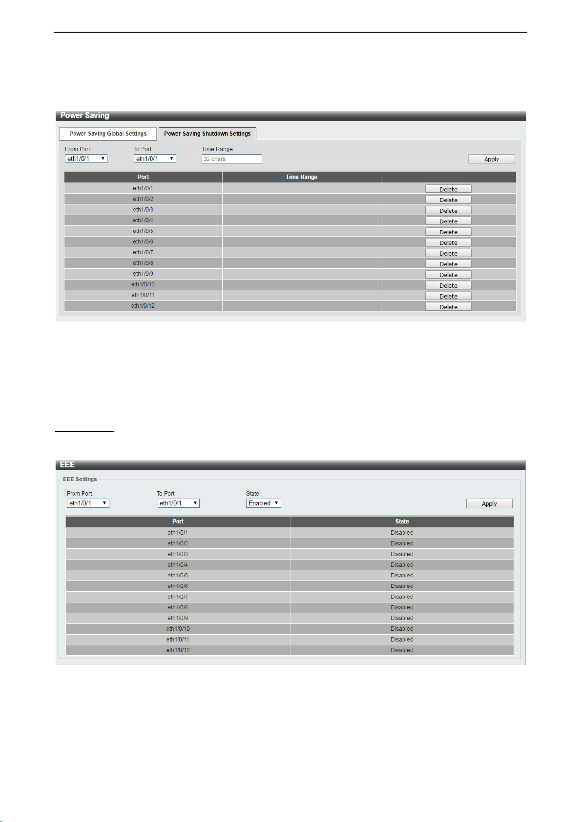
D-Link DXS-1210 Series User Manual
124
Click the Delete button to remove the specified entry.
After clicking the Power Saving Shutdown Settings tab, the following page will appear.
Figure 4.205 – Green > Power Saving – Shutdown Settings
From Port / To Port: Select the range of ports to be configured.
Time Range: Enter the time range to associate with the specified ports.
Click the Apply button to save your settings.
Green > EEE
The Energy Efficient Ethernet (EEE) is defined in IEEE 802.3az. It is designed to reduce the energy
consumption of a link when no packets are being sent.
Figure 4.206 – Green > EEE
From Port / To Port: Select the range of ports to be configured.
State: Select to enable or disable the EEE feature.
Click the Apply button to save your settings.

D-Link DXS-1210 Series User Manual
125
Appendix A - Technical Specifications
Hardware Specifications
Key Components / Performance
Switching Capacity:
- DXS-1210-10TS: 200Gbps
- DXS-1210-12TC: 240Gbps
- DXS-1210-12SC: 240Gbps
- DXS-1210-16TC: 320Gbps
Max. Forwarding Rate
- DXS-1210-10TS: 148.8Mpps
- DXS-1210-12TC: 178.56Mpps
- DXS-1210-12SC: 178.56Mpps
- DXS-1210-16TC: 238.08Mpps
Forwarding Mode: Store and Forward
Packet Buffer memory:
- DXS-1210-10TS: 2Mbytes
- DXS-1210-12TC: 2Mbytes
- DXS-1210-12SC: 2Mbytes
- DXS-1210-16TC: 2Mbytes
DDRIII for CPU: 256 MBytes
Flash Memory: 64 MBytes
Port Functions
10GBASE-T ports compliant with the
following standards:
- 10GBASE-T: IEEE 802.3an
- 1000BASE-T: IEEE 802.3ab
- Supports Full-Duplex operations
- IEEE 802.3x Flow Control support for Full-
Duplex mode
- Auto MDI/MDIX
- Auto-negotiation
- Head-of-line blocking prevention
10GE SFP/SFP+ ports compliant with the
following standards:
- IEEE 802.3z
- IEEE 802.3ae
1000BASE-T transceivers supported:
- DGS-712 (1000BASE-TX)
SFP transceivers:
- DEM-310GT (1000BASE-LX, 10km)
- DEM-311GT (1000BASE-SX, 550m)
- DEM-312GT2 (1000BASE-SX, 2km)
- DEM-314GT (1000BASE-LHX, 50km)
- DEM-315GT (1000BASE-ZX, 80km)
SFP WDM Transceiver:
- DEM-330T/R (1000BASE-BX, 10km)
- DEM-331T/R (1000BASE-BX, 40km)
- DEM-302S-BXD (1000BASE-BX-D Single-
Mode, 2KM(TX-1550/RX-1310 nm))
- DEM-302S-BXU (1000BASE-BX-U Single-
Mode, 2KM(TX-1310/RX-1550 nm))
SFP+ Transceiver:
- DEM-431XT: 10GBASE-SR 80m
- DEM431XT-DD: 10GBASE-SR, 80m
- DEM-432XT: 10BASE-LR, 10km
- DEM-432XT-DD: 10GBASE-LR, 10km
- DEM-433XT: 10GBASE-ER, 40km
- DEM-433XT-DD: 10GBASE-ER, 40km
- DEM-434XT: 10GBASE-ZR, 80km
WDM SFP+ Transceiver:
- DEM-436XT-BXU: 10GBASE-LR 20km
- DEM-436XT-BXD: 10GBASE-LR 20km
CWDM SFP+ Transceiver:
- DEM-X10CS-1271: 10G Single-Mode
10KM CWDM SFP+ Transceiver
- DEM-X10CS-1291: 10G Single-Mode
10KM CWDM SFP+ Transceiver
- DEM-X10CS-1311: 10G Single-Mode
10KM CWDM SFP+ Transceiver
- DEM-X10CS-1331: 10G Single-Mode
10KM CWDM SFP+ Transceiver
- DEM-X40CS-1471: 10G Single-Mode
40KM CWDM SFP+ Transceiver
- DEM-X40CS-1491: 10G Single-Mode
40KM CWDM SFP+ Transceiver
- DEM-X40CS-1511: 10G Single-Mode
40KM CWDM SFP+ Transceiver
- DEM-X40CS-1571: 10G Single-Mode
40KM CWDM SFP+ Transceiver
Support following Direct Attach
Cable(DAC):
- DEM-CB100S
- DEM-CB300S
- DEM-CB700S
Physical & Environment
AC input, 100~240 VAC, 50/60Hz,
internal universal power supply
Acoustic Value:
- DXS-1210-10TS: 44.6dB (2 Fans)
- DXS-1210-12TC: 44.9dB (2 Fans)
- DXS-1210-12SC: 39.2dB (2 Fans)
- DXS-1210-16TC: 39.2dB (2 Fans)
Operation Temperature -5~50°C
Storage Temperature -40~70°C
Operation Humidity: 0%~95% RH
Storage Humidity: 0%~95% RH
Emission (EMI) Certifications
FCC class A

D-Link DXS-1210 Series User Manual
126
CE Class A
VCCI Class A
IC Class A
C-Ticket Class A
BSMI Class A
CCC Class A
Safety Certifications
cUL, CB, CE, CCC, BSMI
Features
L2 Features
Supports up to 16K MAC address
Jumbo frame: Supports up to 9KB
IGMP snooping: Supports 128 multicast
group
MLD Snooping
802.1D Spanning Tree
802.1s MSTP
802.1w Rapid Spanning Tree
ERPS
Loopback Detection
802.3ad Link Aggregation:
- DXS-1210-10TS: up to 8 groups per
device and 8 ports per group
- DXS-1210-12TC: up to 8 groups per
device and 8 ports per group
- DXS-1210-12SC: up to 8 groups per
device and 8 ports per group
- DXS-1210-16TC: up to 8 groups per
device and 8 ports per group
Port mirroring
L3 Features
ARP:
- Max 16K ARP entries
- Support 128 static ARP
- Support Gratuitous ARP
Support 8 IPv4 and 16 IPv6 interfaces
Support IPv4 address 0.0.0.0 to prevent
occupied IP address in the network
Support IPv6 Neighbor Discovery:
- Max 384 ND entries
- Support up to 63 static ND entries
Max. 64 IPv4 and 64 IPv6 static route
entries
Support secondary route
Max. 768 IPv4 and 384 IPv6 host route
D-Link Green Technology
Compliant with RoHS6.
Support D-Link Green v3.0 power saving
mode.
D-Link Green Ethernet:
- Power Saving by LED Shut-Off:
Powered LEDs can be turned
on/off by port or system through
schedule
- Power Saving by Port Shut-Off:
Each port on the system can be
turned on/off by schedule
- Power Saving by System
Hibernation: System enters
hibernation by schedule. In this
mode, switches get most power-
saving figures since main chipsets
(both MAC and PHY) are disabled
for all ports.
Energy Efficient Ethernet (EEE): EEE is
disabled by default, user can enable EEE
via Web GUI
VLAN
802.1Q VLAN standard (VLAN Tagging)
Up to 4K VLAN groups
Asymmetric VLAN
QoS (Quality of Service)
Be able to classify packets according to
follow contents:
- 802.1p priority
- VLAN
- MAC address
- Ether Type
- IP address
- DSCP
- Protocol type
- TCP/UDP port number
- IPv6 traffic class
- IPv6 flow label
- TCP/UDP port number Up to 8 queues
per port
Supports Strict / WRR / Strict+WRR /
Deficit Round Rbin(DRR) / Strict_DRR
mode in queue handling
Bandwidth Control
ACL
Max 50 ingress ACL profile, 512 ingress
ACL rules, 50 VLAN ACL rules.
Each rule can be associated to a single
port, multiple ports
Supports following actions after analyzing
packets:
- Permit
- Deny
Support different ACL policy packet
contents:
- MAC address
- Ethernet Type
- IP address
- ICMP
- IGMP

D-Link DXS-1210 Series User Manual
127
- TCP/UDP port number
- 802.1p
- DSCP
- IPv6 traffic class
- IPv6 flow label
Security
Port Security: Support 64 MACs per port
IP and MAC ACL
Broadcast Storm Control
D-Link Safeguard Engine
DHCP Server Screening over IPv4 or
IPv6 : Maximum 5 entries
SSL: Support v1/v2/v3
Support DHCP Snooping
IP-MAC-Port Binding
- Supports ARP packet Inspection as default,
ARP and IPv4 packet Inspection as option.
- Supports IPv4 DHCP Snooping
Management
Web-based GUI (IPv6 support)
D-Link proprietary CLI
Telnet Server: Max. 4 connections (IPv6
support)
TFTP Client over IPv4 or IPv6
SNMP v1/2c/3 over IPv4 or IPv6
SNMP Trap
DHCP client over IPv4 or IPv6
RMON v1/v2
Trap setting for destination IP, system
events, fiber port events, twisted-pair port
events
Web-based configuration backup /
restoration
Web-based firmware backup/restore
Firmware upgrade Web-based
management
Reset, Reboot