
1
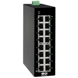
8-Port Unmanaged Industrial
Gigabit 10/100/1000 Ethernet
Switch with EIP QoS, DIN or
Wall-Mountable
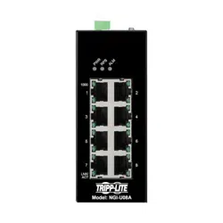
Model: NGI-U08A
1111 W. 35th Street, Chicago, IL 60609 USA • tripplite.com/support
Copyright © 2022 Tripp Lite. All rights reserved.
Owner's Manual
Este manual está disponible en español en la página de Tripp Lite:
tripplite.com
Ce manuel est disponible en français sur le site Web de Tripp Lite :
tripplite.com
Русскоязычная версия настоящего руководства представлена на
веб-сайте компании Tripp Lite по адресу: tripplite.com
Dieses Handbuch ist in deutscher Sprache auf der Tripp Lite-Website
verfügbar: tripplite.com
WARRANTY REGISTRATION
Register your product today and be
automatically entered to win an ISOBAR
®
surge protector in our monthly drawing!
tripplite.com/warranty

2
• NGI-U08A 10/100/1000 Ethernet Switch with EIP QoS
• DIN Rail-Mounting Clip (Preinstalled)
• Owner’s Manual
• 8 auto-negotiable 10/100/1000 Mbps RJ45 ports
• Supports 10/100/1000Base-T, Full Duplex and auto MDI/MDI-X
crossover function
• Simple plug-and-play installation and operation with no
configuration required
• Rugged high-strength case
• Industrial temperature switch models support operating
temperature range of -40°F to 167°F (-40°C to 75°C)
• Easy-to-read LEDs indicate connection and activity status for
each port
• Meets the following IEEE standards:
o IEEE 802.3 10Base-T
o IEEE 802.3u 100Base-TX
o IEEE 802.3 Auto Negotiation
o IEEE 802.3x Flow Control
o IEEE 802.1p Class of Service
Package Contents
Product Features

3
Product Features
Optional Accessories
• Supports MAC address auto-learning and auto-aging
• EIP/QoS/Flow and Storm Control
• Preinstalled durable rail clip mounts firmly to any standard
35 mm DIN rail
• N001-Series Cat5e 350 MHz Snagless UTP Cables
• N002-Series Cat5e 350 MHz UTP Ethernet Cables
• N200-Series Cat6 Gigabit Molded UTP Ethernet Cables
• N201-Series Cat6 Gigabit Snagless Molded UTP Ethernet
Cables
4
8-Port Unmanaged Industrial Gigabit 10/100/1000 Ethernet
Switch with EIP QoS, DIN or Wall-Mountable
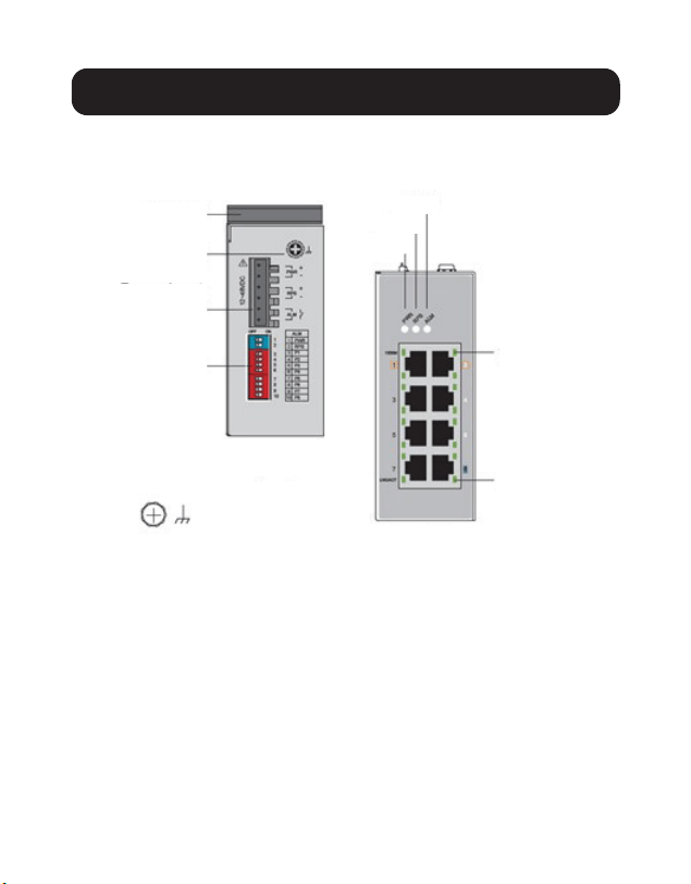
Product Overview
DIN Rail
Grounding
Screw
Power Input
Terminal Block
DIP Switches
Top View
Front View
1000 Mbps
LNK/ACT
Grounding Screw
PWR
RPS
ALM
5
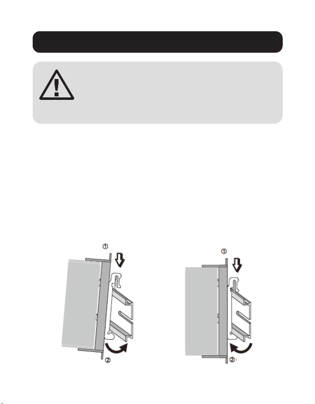
DIN-Rail Mounting and Dismounting Instructions
Mounting the Switch Removing the Switch
Click
Push
Push
Click
ATTENTION: The NGI-U08A is an open-type device
and shall be DIN-rail mounted or wall mounted
(optional) in a cabinet or rack enclosure. The
ambient temperature should not exceed 75°C
(167°F).
Mounting the Switch
Place the switch on the DIN rail from above using the built-in
slot. Push the front of the switch toward the mounting surface
until it snaps into place. You will hear a “click” to indicate it has
successfully snapped into place.
Dismounting the Switch
Press the switch from the top, then pull out the lower edge of the
switch to remove it from the DIN rail.

6
DIN-Rail Mounting and Dismounting Instructions
ATTENTION: A corrosion-free DIN mounting rail is
advisable. When mounting the switch, be sure to
allow enough space between devices to install the
cabling and to ensure proper airflow.
Grounding the Switch
Grounding and wire routing help limit the effects of line noise
caused by electromagnetic interference (EMI). Run the ground
connection from the ground screw to the grounding surface, then
connect the ground connection from the terminal block to the
grounding surface prior to connecting devices.
ATTENTION: This switch is intended for mounting on a well-
grounded surface, such as a metal panel.

7
WARNING: Safety measures should be taken before
connecting the power cable. Turn off the power before
connecting modules or wires. The correct power supply
voltage is listed on the product label. Check the voltage
of your power source to make sure you are using the
correct voltage. DO NOT use a voltage greater than
what is specified on the product label. Calculate the
maximum possible current in each power wire and
common wire. Confirm all electrical codes dictating
the maximum current allowable for each wire size. If
current exceeds the maximum rating, the wiring can
overheat causing serious damage to your equipment.
Please read and follow these guidelines:
• Use separate paths to route wiring for power and devices. If
power wiring and device wiring paths must cross, make sure
the wires are perpendicular at the intersection point.
Note: Do not run signal or communications wiring and power wiring
through the same wire conduit. To avoid interference, wires with
different signal characteristics should be routed separately.
• You can use the type of signal transmitted through a wire
to determine which wires should be kept separate. Wiring
that shares similar electrical characteristics can be bundled
together.
• You should separate input wiring from output wiring.
• Be advised that you should label the wiring to all devices in the
system.
Wiring Requirements
8
Wiring Requirements
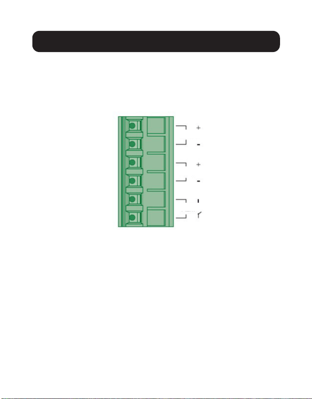
Wiring Power Input
You can use “PWR” for Primary Power input and “RPS” for
Redundant Power Input. Check the polarity while connecting. The
top view of the Terminal Block is shown in the figure below:
CAUTION:
• Use copper conductors only.
• Wiring cable temperature should support at least 105°C
(221˚F).
• Tighten the wire to a torque value 0.5 N•m (4.5 in•lb).
Note: The wire gauge for the terminal block should range between 12
and 24 AWG.
Terminal Block
PWR
RPS
ALM

9
Wiring Requirements
To insert power wire and connect the specified voltage and
maximum electric current to the power terminal block, follow
these steps:
• Use a flat-head screwdriver to loosen the wire-clamp screws.
• Insert the negative/positive DC wires into the PWR-/PWR+
terminals, respectively.
• Tighten the wire-clamp screws to prevent the wires from
loosening.
ATTENTION: Use a power supply from 12~48VDC, 0.5A
maximum. The device power shall be supplied by LPS circuit.
10
Wiring Requirements
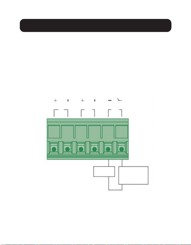
Wiring the Relay Contact (ALM)
The switch has one set of relay alarm output. This relay contact
uses two contacts of the terminal block on the switch top panel.
The two contacts of the 6-pin terminal block connector are used
to detect user-configured events. The two wires attached to the
fault contacts form an open circuit when a user-configured event
is triggered. If a user-configured event does not occur, the fault
circuit remains closed.
Load
Relay rating: 24V, 1A
External
Power
PWR
RPS
ALM

11
Cabling
Connect one end of an RJ45 Ethernet cable (see Optional
Accessories) into the switch’s RJ45 Ethernet port. Connect
the other end to a network device. Cat5e cable or above is
recommended.
• Ports 1-8 of the switch support Gigabit Ethernet (10/100/1000
Mbp speeds)
• All ports support auto-negotiation and auto MDI/MDI-X to
eliminate the need for crossover cabling.
DIP Switch Settings
PWR
ON Primary power alarm reporting is enabled
OFF Primary power alarm reporting is disabled
RPS
ON Redundant power alarm reporting is enabled
OFF Redundant power alarm reporting is disabled
P1
ON Port 1 link alarm reporting is enabled
OFF Port 1 link alarm reporting is disabled

12
Cabling
P2
ON Port 2 link alarm reporting is enabled
OFF Port 2 link alarm reporting is disabled
P3
ON Port 3 link alarm reporting is enabled
OFF Port 3 link alarm reporting is disabled
P4
ON Port 4 link alarm reporting is enabled
OFF Port 4 link alarm reporting is disabled
P5
ON Port 5 link alarm reporting is enabled
OFF Port 5 link alarm reporting is disabled
P6
ON Port 6 link alarm reporting is enabled
OFF Port 6 link alarm reporting is disabled
P7
ON Port 7 link alarm reporting is enabled
OFF Port 7 link alarm reporting is disabled
P8
ON Port 8 link alarm reporting is enabled
OFF Port 8 link alarm reporting is disabled

13
LED Indicators
PWR (Green)
Illuminated Primary power on
Off Primary power off or failure
RPS (Green)
Illuminated Redundant power on
O Redundant power o or failure
ALM (Red)
Illuminated
Alarm triggered for abnormal
power or port link down status
Off Normal operation or DIP switch off
1000 (Green)
1-8 RJ45 Ports
Illuminated Link speed at 1000 Mbps
O Link speed at 10/100 Mbps
LNK/ACT (Green)
1-8
RJ45 Ports
Illuminated Port link up
Blinking
Activity (receiving or transmitting
data)
O Port disconnected or link failed

14
Specications
Power
Input Voltage Dual-power inputs 12-48VDC/0.5A
Connection 6-pin terminal block
Reverse Polarity
Protection
Present
Power Consumption
(System Only)
5W
Grounding Screw Present
Interface
RJ45 8 x 10/100/1000Base-T, auto-negotiation,
auto-MDI/MDI-X, Full/Half Duplex and Flow
Control
LED PWR (Green): Power
RPS (Green): Power by terminal block RPS
ALM (Red): Power and RPS fails and RJ45
port link down
1000 (Green): Port 1~8 1000 Mbps
Ethernet speed at 100 Mbps
LNK/ACT (Green): Port 1~8 data
transmitting/receiving
Alarm Relay Output 1 alarm relay output for power loss and port
link down

15
Specications
Environmental
Operating Temperature -40°C to 75°C (-40°F to 167°F)
Storage Temperature -40°C to 85°C (-40°F to 185°F)
Operating Humidity 5 to 95% (Non-Condensing)
Storage Humidity 5 to 95% (Non-Condensing)
Operating Altitude 2000 m
Regulatory Approvals
EMI/EMC FCC Part 15
EN 55011 / BS EN 55011
EN 61000-6-4 / BS EN 61000-6-4
EN IEC 61000-6-2 / BS EN 61000-6-2
EN 55032 / BS EN 55032
EN 55024
ATTENTION: If the switch is used in a manner not specified here,
the protection provided by the switch may be impaired.

16
Warranty and Product Registration
3-Year Limited Warranty
Seller warrants this product, if used in accordance with all applicable instructions,
to be free from original defects in material and workmanship for a period of three
(3) years from the date of initial purchase. If the product should prove defective in
material or workmanship within that period, Seller will repair or replace the product,
at its sole discretion.
THIS WARRANTY DOES NOT APPLY TO NORMAL WEAR OR TO DAMAGE RESULTING
FROM ACCIDENT, MISUSE, ABUSE OR NEGLECT. SELLER MAKES NO EXPRESS
WARRANTIES OTHER THAN THE WARRANTY EXPRESSLY SET FORTH HEREIN. EXCEPT
TO THE EXTENT PROHIBITED BY APPLICABLE LAW, ALL IMPLIED WARRANTIES,
INCLUDING ALL WARRANTIES OF MERCHANTABILITY OR FITNESS, ARE LIMITED IN
DURATION TO THE WARRANTY PERIOD SET FORTH ABOVE; AND THIS WARRANTY
EXPRESSLY EXCLUDES ALL INCIDENTAL AND CONSEQUENTIAL DAMAGES. (Some
states do not allow limitations on how long an implied warranty lasts, and some
states do not allow the exclusion or limitation of incidental or consequential
damages, so the above limitations or exclusions may not apply to you. This warranty
gives you specific legal rights, and you may have other rights which vary from
jurisdiction to jurisdiction.)
WARNING: The individual user should take care to determine prior to use
whether this device is suitable, adequate or safe for the use intended. Since
individual applications are subject to great variation, the manufacturer makes no
representation or warranty as to the suitability or fitness of these devices for any
specific application.
Product Registration
Visit tripplite.com/warranty today to register your new Tripp Lite product. You’ll be
automatically entered into a drawing for a chance to win a FREE Tripp Lite product!*
*No purchase necessary. Void where prohibited. Some restrictions apply. See
website for details.

17
Warranty and Product Registration
WEEE Compliance Information for Tripp Lite Customers and
Recyclers (European Union)
Under the Waste Electrical and Electronic Equipment (WEEE) Directive
and implementing regulations, when customers buy new electrical and
electronic equipment from Tripp Lite, they are entitled to:
• Send old equipment for recycling on a one-for-one, like-for-like basis
(this varies depending on the country)
• Send the new equipment back for recycling when this ultimately
becomes waste
FCC Notice, Class B
This device complies with part 15 of the FCC Rules. Operation is subject to the
following two conditions: (1) This device may not cause harmful interference, and
(2) this device must accept any interference received, including interference that
may cause undesired operation.
Note: This equipment has been tested and found to comply with the limits for
a Class B digital device, pursuant to part 15 of the FCC Rules. These limits are
designed to provide reasonable protection against harmful interference in a
residential installation. This equipment generates, uses and can radiate radio
frequency energy and, if not installed and used in accordance with the instructions,
may cause harmful interference to radio communications. However, there is
no guarantee that interference will not occur in a particular installation. If this
equipment does cause harmful interference to radio or television reception, which
can be determined by turning the equipment off and on, the user is encouraged to
try to correct the interference by one or more of the following measures:
• Reorient or relocate the receiving antenna.
• Increase the separation between the equipment and receiver.
• Connect the equipment into an outlet on a circuit different from that to which the
receiver is connected.
• Consult the dealer or an experienced radio/TV technician for help.
Any changes or modifications to this equipment not expressly approved by Tripp Lite
could void the user’s authority to operate this equipment.

18
Use of this equipment in life support applications where failure of this equipment
can reasonably be expected to cause the failure of the life support equipment or to
significantly affect its safety or effectiveness is not recommended.
Tripp Lite has a policy of continuous improvement. Specifications are subject to
change without notice. Photos and illustrations may differ slightly from actual
products.
Warranty and Product Registration

19

20
1111 W. 35th Street, Chicago, IL 60609 USA • tripplite.com/support
22-10-200-9346C9_RevA