Loading ...
Loading ...
Loading ...
Boiler manual: • Installation • Start-Up • Maintenance • Parts
9Part No. 550-110-275/1018
Assembling the block
(continued)
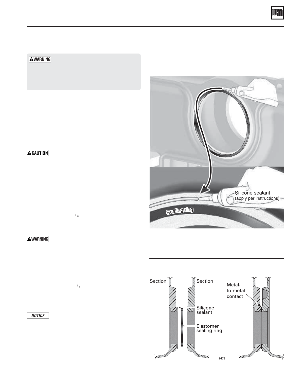
Figure 7 Applying silicone sealant around outsides of sealing
rings (shown on 94 intermediate section upper nipple
port)
Figure 8 Sealing ring installation and port alignment, typical
Weil-McLain cast iron section nipple port
Silicone sealant applied as specified above
prevents unburned oil vapors from coming
in contact with sealing ring. Vapor con-
tact can damage rings, resulting in severe
damage to boiler and substantial property
damage.
Raise the rear section upright
1. Hoist the back section upright.
2. Move rear section into position on the steel rails. The
section should be 4 inches from the end of the founda-
tion (if used) as shown in Figure 1, page 4.
3. Block under the flueway outlet to hold the rear section
upright in plumb position.
The back section must be plumb before in-
stalling other sections to ensure the block will
assemble correctly.
4. The blocking under the flueway can be removed later,
after several intermediate sections have been attached
and the assembly is stable.
5. Install intermediate sections and front section as de-
scribed on the following.
Install intermediate sections
1. Remove and discard
3
⁄8" diameter shipping tie rods.
2. Remove grit from port machined surfaces with clean
rag. Also remove grit from tapped holes in all sections.
Do not use petroleum-based cleaning or
sealing compounds in boiler system. Severe
damage to system components can result,
causing substantial property damage.
3. Position intermediate section so aligning lugs fit into
sockets of next section. See Figure 8.
4. Draw sections together until metal-to-metal contact is
made around machined port openings (see Figure 8):
a. Oil threads on (4)
5
⁄8" x 11" draw rods. Install washer
and nut on end to be tightened. Use nut only on
other end.
b. Uniformly draw sections together, starting at
washer/nut end.
Important — Leave an equal amount of thread
on each end of the draw rod. This is needed
to allow securing the jacket support brackets
in place. The draw rods must not extend past
the face of the front or back section, or they
will interfere with the jacket.
c. Draw rods should be torqued to a range of 100 to
120 ft-lbs. Do not back off draw rods.
d. Metal-to-metal contact will be achieved around port
openings. See Figure 8. If gap occurs, it should be no
greater than .032". Check with feeler gauge.
Loading ...
Loading ...
Loading ...