Loading ...
Loading ...
Loading ...
Boiler manual: • Installation • Start-Up • Maintenance • Parts
13Part No. 550-110-275/1018
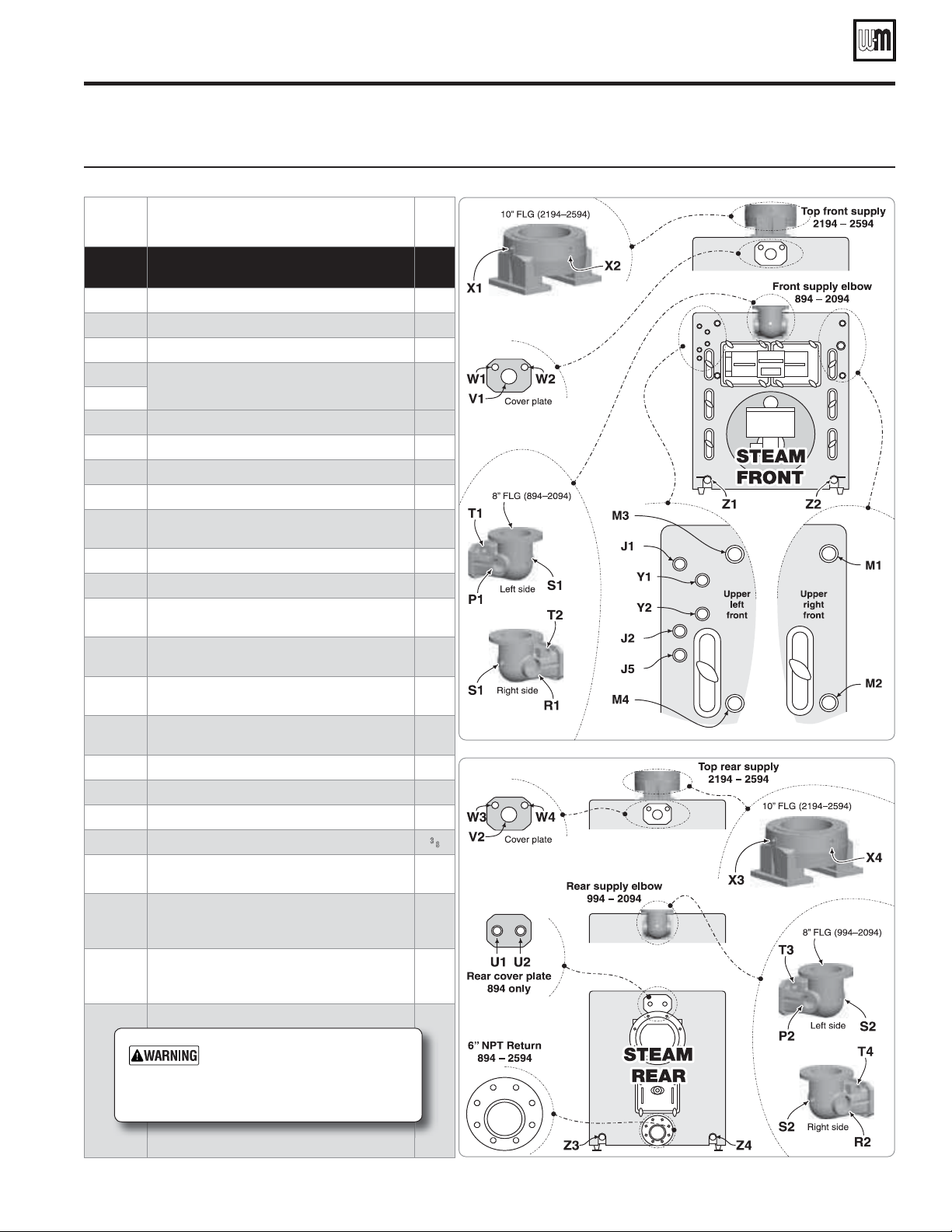
Control tapping locations — steam boilers
Figure 11 Model 94 steam boiler control tappings
Item # Function Size
(Inches
NPT)
J1
PRESSURE TEST GAUGE — REMOVE AFTER
HYDROSTATIC TEST
½
J1 + J5
Gauge glass
½
J2
PLUG this tapping — not used
½
M3
PLUG this tapping — not used
1
M1 + M2
Float-type low water cutoff, LWCO/pump control or
LWCO/feeder combination
1
M3 + M4
P1 Skim tapping
3
P2 Steam pressure relief valve
3
R1 Skim tapping
4
R2 Steam pressure relief valve
4
S1
Steam pressure gauge — or —
Pressure controls (limit, operating, etc.)
¾
S2 Pressure controls (limit, operating, etc.)
¾
T1 or T2 Pressure controls (limit, operating, etc.)
1¼
T3 or T4
Steam pressure gauge — or —
Pressure controls (limit, operating, etc.)
1¼
U1 or U2
Steam pressure relief valve — Install relief valve in
one tapping and plug the other
2
V1 or V2
Steam pressure relief valve — or —
Skim tapping
4
W1 or W2
Steam pressure gauge — or —
Pressure controls (limit, operating, etc.)
¾
W3 or W4 Pressure controls (limit, operating, etc.)
¾
X1 & X2
PLUG these tappings — not used
1¼
X3 & X4
PLUG these tappings — not used
1¼
Y1 & Y2 Try cocks
3
⁄8
Z1 or Z2
Cleanout tappings — Front section — Install 2" NPT
close nipple and 2" NPT cap in each cleanout tapping
2
Z3 or Z4
Cleanout or drain tappings — Rear section —
Install drain valve in one tapping; install 2" NPT x 2½"
length nipple and 2" NPT cap in the other
2
—
Low limit temperature control (when using tankless
heaters) — locate in control tapping on one of the tankless
heaters
—
Controls and fi ttings must not
obstruct cleanout openings or
prevent required access to the
boiler or components.
Loading ...
Loading ...
Loading ...