
Loading ...
Loading ...
Loading ...
Weil-McLain 94 Series 3 Water and steam boilers — for Gas, Light Oil, & Gas/Light Oil-Fired Burners
24 Part No. 550-110-275/1018
Complete block assembly & install jacket
(continued)
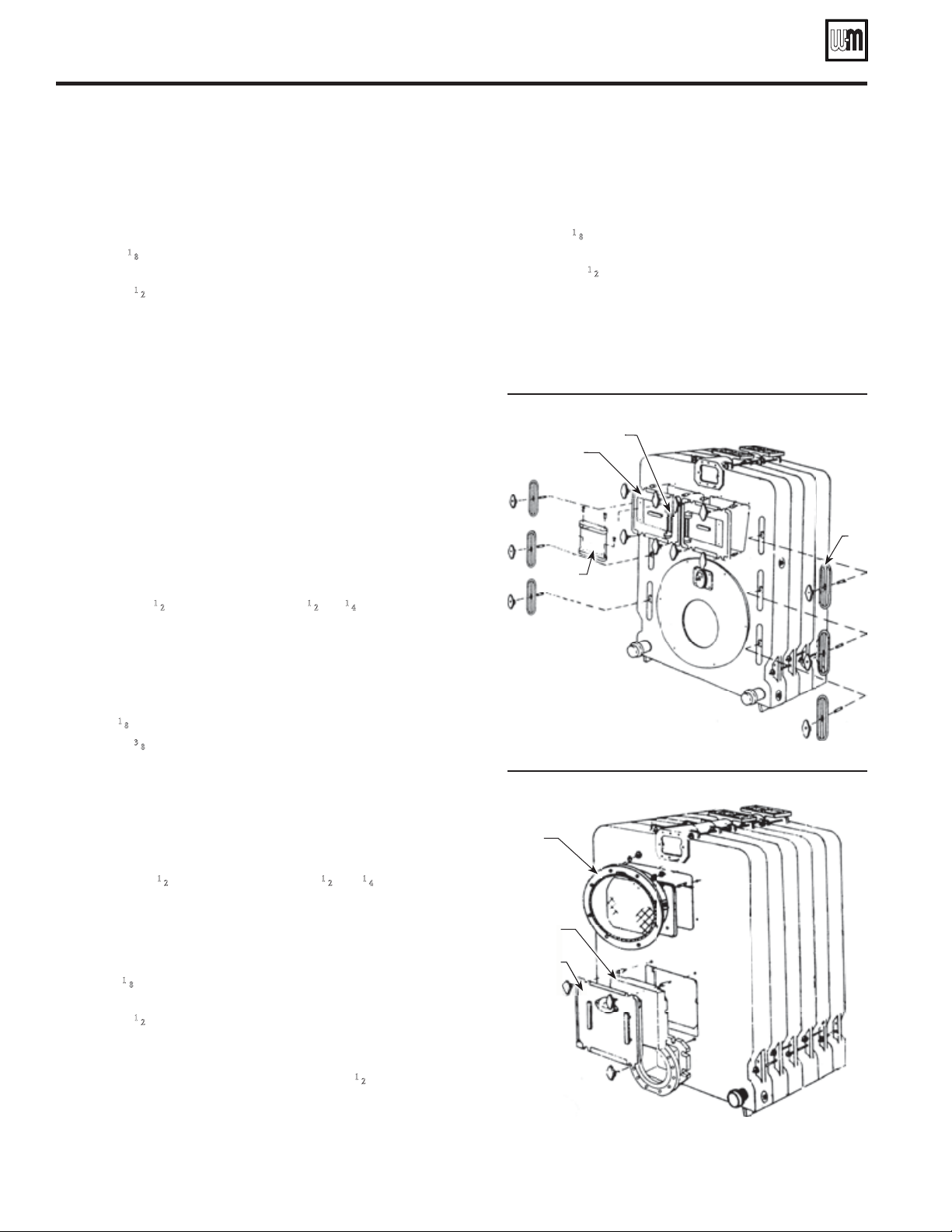
Install front cleanout doors
1. See Figure 28, items K20 (cleanout door assembly), K22 (hinge
for cleanout door), K22 (hinge for cleanout door) and K24 (hinge
plate for cleanout door).
2. Apply a
1
⁄8" continuous bead of rope adhesive in the grooves around
the cleanout doors.
3. Position
1
⁄2" sealing rope in grooves, overlapping ends at least 1".
4. Secure 8 mounting studs in tapped holes located around cleanout
openings.
5. Position cleanout door with hinge closest to centerline of front
section over 4 studs.
6. Hand tighten 4 wing nuts to secure door to section.
7. Attach cleanout door hinge plate to installed door. Use two hinge
pins.
8. Attach other door to hinge plate. Use two hinge pins.
9. Close second door. Hand tighten 4 wing nuts to secure door to
section.
10. Affi x boiler nameplate to hinge plate. Use 2 drive screws.
Install front cleanout plates
1. See Figure 28, item M (cleanout plates).
2. Thread two
1
⁄2" nuts on round end of
1
⁄2" x 4
1
⁄4" stud. Lock the nuts
together.
3. Thread fl at end of stud into tapped hole in one of the clean-out
openings.
4. Remove nuts.
5. Repeat steps 1-3 for remaining 5 studs.
6. Apply
1
⁄8" continuous bead of rope adhesive in groove around plates.
7. Position
3
⁄8" sealing rope in groove, overlapping ends at least 1".
8. Insert a cleanout plate into each opening. Secure with hand-
tightened wing nut.
Install fl ue collar on rear section
1. See Figure 29, item D (fl ue collar assembly).
2. Thread two
1
⁄2" nuts on round end of
1
⁄2" x 4
1
⁄4" stud. Lock nuts
together.
3. Thread fl at end of stud into tapped hole inside fl ueway outlet.
4. Remove nuts.
5. Repeat steps 1 through 3 for the remaining 3 studs.
6. Apply
1
⁄8" continuous bead of rope adhesive in groove around
fl ue collar.
7. Position
1
⁄2" sealing rope in groove, overlapping ends at least 1".
8. Position fl ue collar over studs. The breeching damper handle must
point up.
9. Tightly secure fl ue collar to rear section using
1
⁄2" nuts and washers.
Install back access door
1. See Figure 29, items K40 (back access door assembly) and
K41(refractory shield for back access door).
2. Insert access door shield into opening in back section.
3. Push against shield until it bottoms against stops.
4. Apply
1
⁄8" continuous bead of rope adhesive in groove
around back access door opening.
5. Position
1
⁄2" sealing rope in groove, overlapping ends
at least 1".
6. Secure four mounting studs in holes around back access
door opening.
7. Position access door assembly over studs.
8. Hand-tighten 4 nuts to secure access door.
Figure 28
Front section block assembly components
K20
K22
K24
M
Figure 29 Rear section block assembly components
K40
D
K41
Loading ...
Loading ...
Loading ...