Loading ...
Loading ...
Loading ...
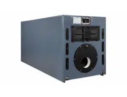
Weil-McLain 94 Series 3 Water and steam boilers — for Gas, Light Oil, & Gas/Light Oil-Fired Burners
28 Part No. 550-110-275/1018
Install steam boiler controls
Install controls:
1. Install controls where shown in Figure 34 and
Figure 35, page 29.
2. Follow Figure 36, page 29 and Figure 38, page 30
for mounting operating controls and water level
controls.
Failure to properly install, pipe and wire
boiler controls can result in severe dam-
age to boiler, building and personnel; and
is not covered by boiler warranty.
a. Install steam pressure operating and high
limit controls and pressure gauge. See Fig-
ure 36, page 29.
b. Pressure limit control settings:
• Low – set according to design requirements.
• High – set at least 2 psi higher than low
limit, 15 psi maximum.
c. Install water level controls and gauge glass per
Figure 38, page 30.
• Fittings for controls to be furnished by
others.
• If water level control is not shown in
Figure 37, page 30, locate casting mark
on control and install per manufacturer's
instructions.
Do not use water level controls with quick
hook-up fittings. Nuisance shutdowns
will occur.
Install and pipe from relief valve
1. Install relief valve(s) where shown in Figure 34 and
Figure 35, page 29.
2. Relief valve must be installed with spindle in verti-
cal position.
3. Do not make any other connection in the relief
valve connection piping.
Pipe relief valve discharge through ver-
tical piping to atmosphere. Use rigid
material suitable for 375°F, threaded one
end only. Install drain pan elbow to drain
condensate. Pipe near floor close to floor
drain to eliminate potential of severe
burns. Do not pipe to any area where
freezing could occur. Do not plug, valve
or place any obstruction in discharge line.
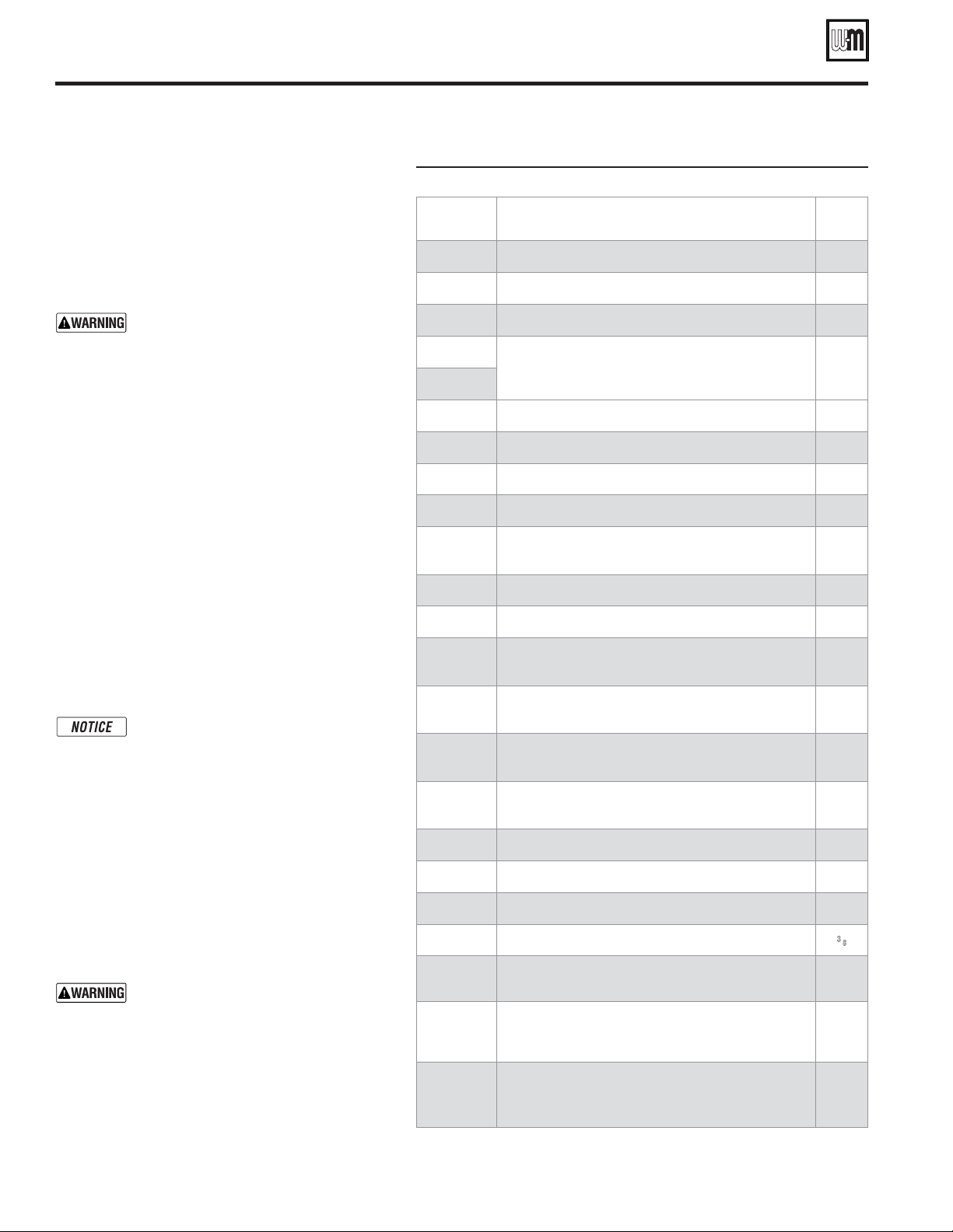
Figure 34 Model 94 steam boiler control tappings
Item # Function Size
(Inches NPT)
J1 + J5
Gauge glass
½
J2
PLUG this tapping — not used
½
M3
PLUG this tapping — not used
1
M1 + M2
Float-type low water cutoff, LWCO/pump control or
LWCO/feeder combination (see Figure 38, page 30)
1
M3 + M4
P1
Skim tapping
3
P2
Steam pressure relief valve
3
R1
Skim tapping
4
R2
Steam pressure relief valve
4
S1
Steam pressure gauge — or —
Pressure controls (limit, operating, etc.)
¾
S2
Pressure controls (limit, operating, etc.)
¾
T1 or T2
Pressure controls (limit, operating, etc.)
1¼
T3 or T4
Steam pressure gauge — or —
Pressure controls (limit, operating, etc.)
1¼
U1 or U2
Steam pressure relief valve — Install relief valve in one
tapping and plug the other
2
V1 or V2
Steam pressure relief valve — or —
Skim tapping
4
W1 or W2
Steam pressure gauge — or —
Pressure controls (limit, operating, etc.)
¾
W3 or W4
Pressure controls (limit, operating, etc.)
¾
X1 & X2
PLUG these tappings — not used
1¼
X3 & X4
PLUG these tappings — not used
1¼
Y1 & Y2
Try cocks
3
⁄8
Z1 or Z2
Cleanout tappings — Front section — Install 2" NPT
close nipple and 2" NPT cap in each cleanout tapping
2
Z3 or Z4
Cleanout or drain tappings — Rear section — Install
drain valve in one tapping; install 2" NPT x 2½" length
nipple and 2" NPT cap in the other
2
—
Low limit temperature control (when using tankless
heaters) — locate in control tapping on one of the tankless
heaters
—
Loading ...
Loading ...
Loading ...