Loading ...
Loading ...
Loading ...
Boiler manual: • Installation • Start-Up • Maintenance • Parts
15Part No. 550-110-275/1018
Connect water boiler piping
(continued)
Figure 14 Recommended minimum pipe sizes when flow rate is
not known (see Figure 12, page 14)
(note 1)
Boiler
model
Supply pipe size
A
Return pipe size
B
894
5" 5"
994 – 1294
6" 6"
1394 – 2094
8" 8"
2194 – 2594
10" 10"
Note 1 Pipe sizes are based on a 20°F temperature rise through the boiler. For
applications with higher flow rates (lower temperature rise), determine
the flow rate and use Figure 13, page 14 to size the piping. DO NOT
use flow rates in excess of 520 GPM through 894–2094 or 820 GPM
through 2194–2594.
Figure 15 ASME drain valve size
Boiler
model
Minimum drain/blow-off
valve size
894 – 994
1¼"
1094 – 2194
1½"
2294 – 2594
2"
Piping multiple boilers
1. See Figure 16. (Expansion tanks, relief valves and other accessories
are required, but omitted from the illustration for simplicity.)
2. The boiler piping circuits are referred to as the secondary circuits
in the following.
3. The legend for Figure 16 and boiler pump sizing recommenda-
tions follow:
A Size boiler pump GPM based on the following:
a. Temp rise = High limit temp – Return water temp
b. GPM =
Boiler Gross Output, Btuh
Temperature rise x 500
c. Calculate only secondary (boiler) piping circuit resistance. Al-
low for head loss through the boiler equal to three 90 degree
elbows of secondary pipe size.
d. Operate each boiler and its pump with a Weil-McLain boiler
control panel.
e. Size secondary (boiler) circuit piping using the flow rate ranges
given in Figure 15.
B Primary pump GPM and head calculation should not include
secondary boiler circuits. Primary pump can operate continuously
during heating season.
C Connection to primary circuit — Space 12" maximum or as close
as practical.
D Check valve.
E Hand valve.
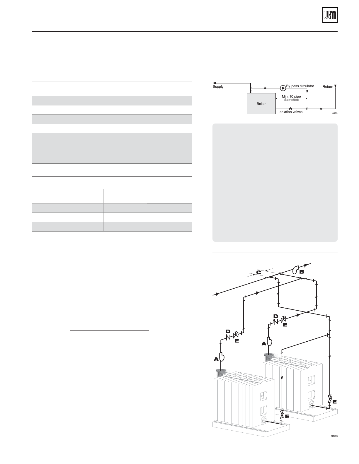
Figure 16 By-pass piping for return water less
than 140°F
By-pass circulator sizing:
1. Size system circulator as required. Determine GPM
and head requirements.
2. Provide a by-pass circulator for EACH boiler. The flow
rate for each by-pass circulator will be:
Flow = ¼ x (System circulator GPM) ÷ (# of boilers)
3. All circulators must run at the same time.
4. Example: For a 1,000,000 Btuh single boiler, with
system temperature drop of 20°F:
• System GPM = 1,000,000 ÷ 20 ÷ 500 = 100 GPM
• By-pass GPM = ¼ x 100 GPM = 25 GPM
• Determine by-pass circuit head loss for pipe size
and fittings used.
5. In most applications, a standard booster pump should
be adequate.
Figure 17 Multiple water boiler piping
Loading ...
Loading ...
Loading ...