Loading ...
Loading ...
Loading ...
Boiler manual: • Installation • Start-Up • Maintenance • Parts
17Part No. 550-110-275/1018
Connect steam boiler piping
(continued)
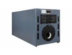
Figure 21 Model 894 steam (1 riser)
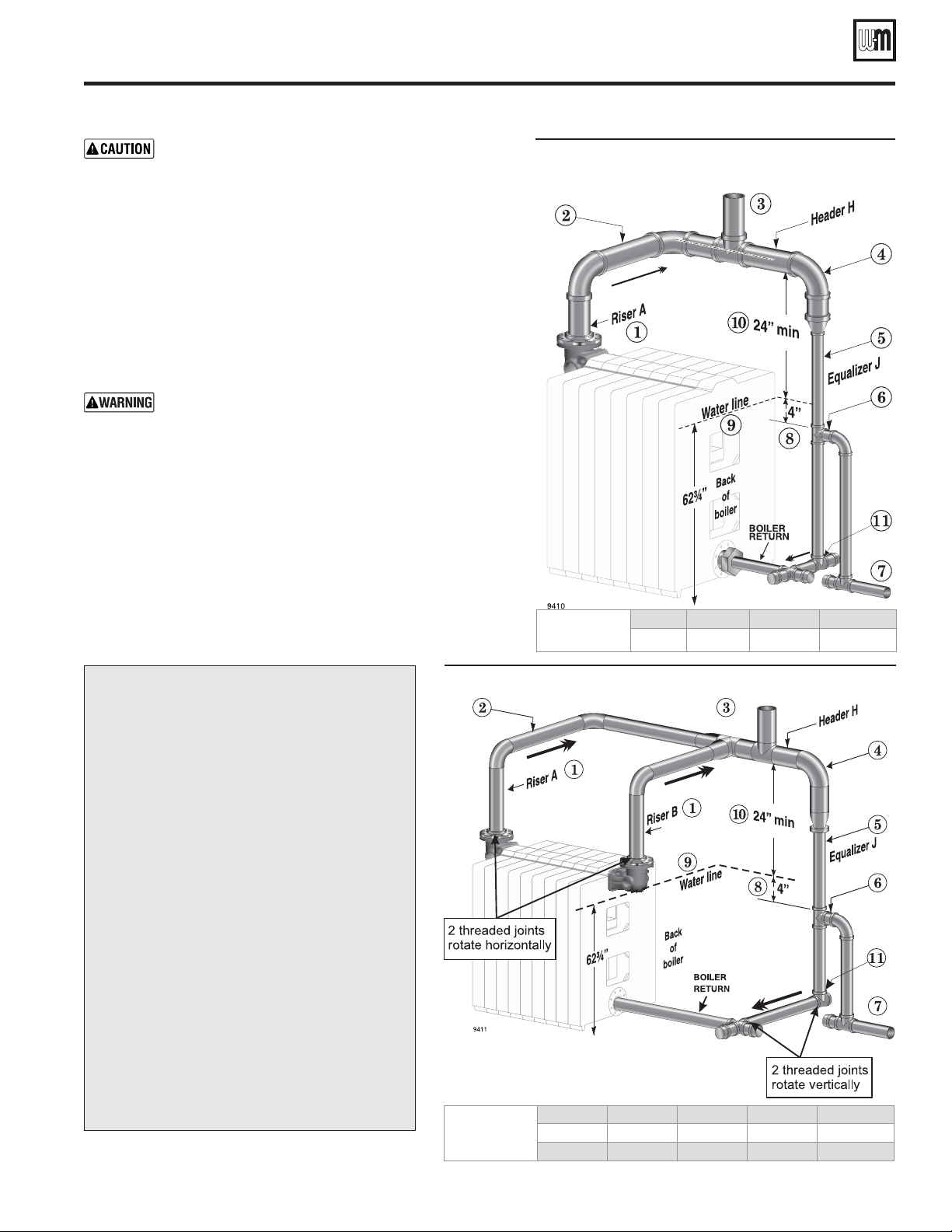
Figure 22 Model 994 through 2094 steam (2 8-inch risers required)
Improperly piped systems or undersized piping can
contribute to erratic boiler operation and possible boiler
or system damage. Piping system must be installed as
shown, using pipe sizes shown. Pipe sizes shown are for
two-pipe, pumped-return systems. Adjust pipe sizing
as needed when connecting to gravity-return systems.
Consult local Weil-McLain distributor or sales office
before installing alternate piping.
Steam boiler piping guidelines
Minimum height of header above water line must
be 24 inches
The boiler header must always be at least 24 inches
above the water line, as shown in all steam boiler pip-
ing diagrams. Installing the pipe lower will result in
increased water carryover to the system, resulting in
potential serious damage to system components and
oxygen corrosion due to excess make-up water.
Hartford loop piping for all steam boilers
1. You must install the system supply pipe between the equalizer
elbow and the last boiler riser pipe connection to the header. This
assists in separating water from the steam as it turns upward into
the steam supply pipe.
2. Locate the top of the Hartford loop return nipple at least 4 inches
below the water line, as shown.
Pipe
Dimensions
Model Riser A Riser B Header H Equalizer J
994-1594 8" 8" 8" 4"
1694-2094 8" 8" 10" 4"
Pipe
Dimensions
Model Riser A Header H Equalizer J
894 8" 8" 4"
Drawing legend & notes
(Figure 21 through Figure 24)
1 Riser pipes (one for each supply outlet)
2 Horizontal pipes needed to offset the header to
allow for expansion and contraction of the header
3 Steam supply must be located between last riser
connection and equalizer elbow
4 Equalizer elbow — full size or reducing
5 Equalizer pipe
6 Close nipple at Hartford loop tee to reduce water
hammer potential
7 Condensate return line (gravity or pumped)
8 Pipe to provide 4 inches between water line and
top of Hartford loop return nipple
9 Boiler water line — all automatic water level con-
trols must be set to maintain this level
10 Minimum 24 inches between water line and bot-
tom of header
11 Offset tee
Loading ...
Loading ...
Loading ...