Loading ...
Loading ...
Loading ...
Weil-McLain 94 Series 3 Water and steam boilers — for Gas, Light Oil, & Gas/Light Oil-Fired Burners
26 Part No. 550-110-275/1018
Install water boiler controls
Install controls:
1. Install furnished controls per Figure 32 and Fig-
ure 33, page 27.
Failure to properly install, pipe and wire
boiler controls can result in severe dam-
age to boiler, building and personnel; and
is not covered by boiler warranty.
2. Relief valve must be installed with spindle in vertical
position. Use fittings provided with boiler. Do not
make any other connection in that piping.
Relief valve discharge line must be piped
using rigid material suitable for 375°F,
threaded one end, near floor close to
drain to eliminate potential of severe
burns. Do not pipe to any area where
freezing could occur. Do not plug, valve
or place any obstruction in discharge line.
3. When installing low water cut-off
a. Must be installed if boiler is located above
radiation level.
b. May be required on water boilers by certain
state, local or territorial codes or insurance
companies.
c. Install low water cutoff designed for water
installations where shown in Figure 32 and
Figure 33, page 27.
d. Pipe float-type low water cut-off(s) with offset
piping to prevent obstruction of boiler access
and cleanout openings. See Figure 38, page 30.
One limit control is supplied with the
boiler. A second limit control must be
supplied by the installer (field installed)
to comply with current ASME Boiler and
Pressure Vessel Code, Section IV.
4. Dual limit control settings:
a. Low – set according to design requirements.
b. High – at least 20° higher than low limit, 240°F
maximum.
5. Install optional controls per control manufacturer's
instructions.
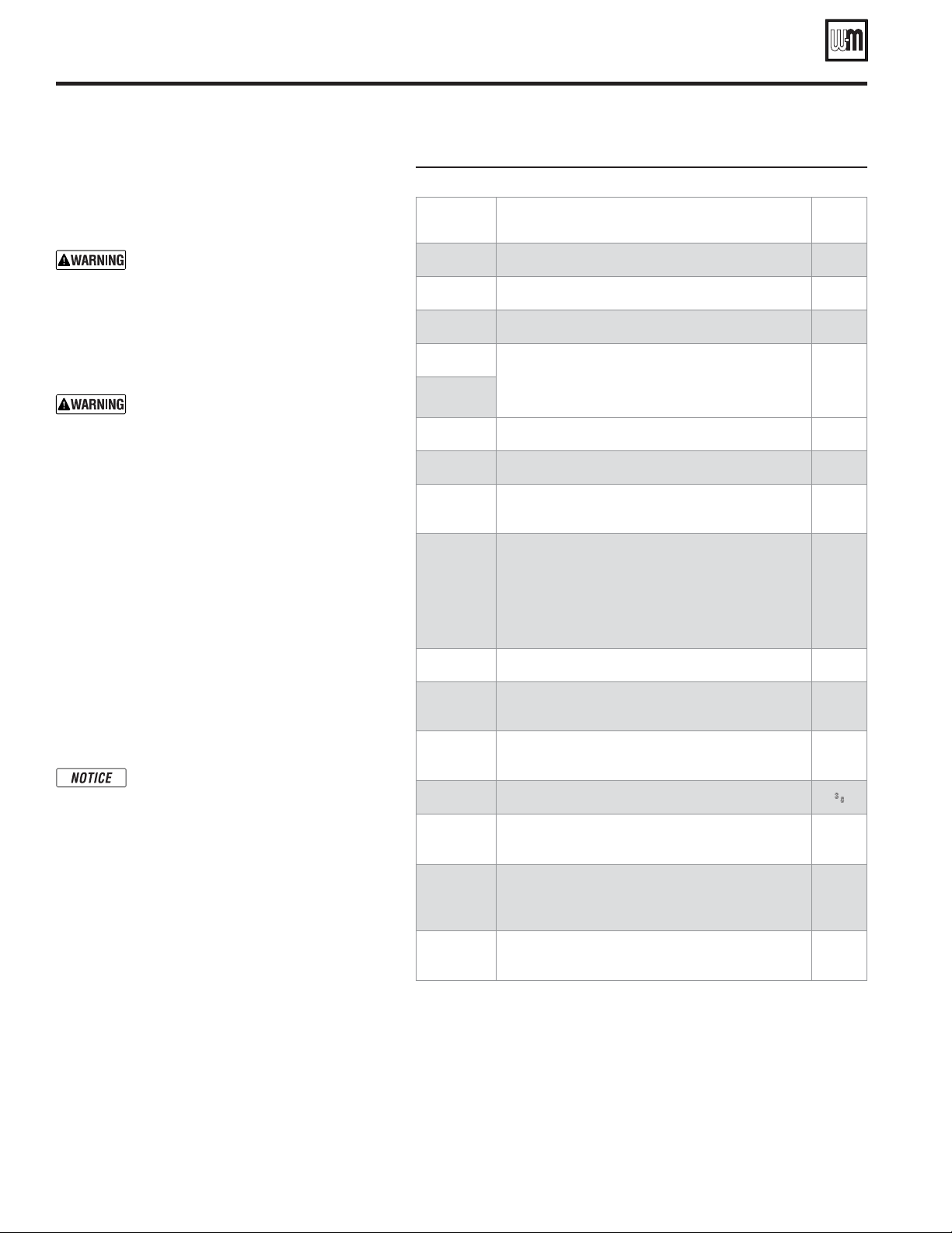
Figure 32 Model 94 water boiler control tappings
Item # Function Size
(Inches NPT)
J1
Temperature control or limit
½
J2 & J5
PLUG these tappings — not used on water boilers
½
M3
Probe-type low water cutoff
1
M1 + M2
Float-type low water cutoff or LWCO/feeder
combination (use offset piping as shown in
Figure 38, page 30)
1
M3 + M4
P1 or R1
Temperature control or limit
3
S1
P/T gauge or temperature gauge
¾
T1 or T2
Temperature control or limit — or —
Air vent piping to compression tank
1¼
U1 & U2
Pressure relief valve(s):
894–2094: Install relief valve in one tapping and plug the
other tapping
2194–2594: Install a relief valve in each tapping (2 relief
valves required on these boilers)
2
V1
Temperature control or limit
4
W1 or W2
Temperature control or limit — or —
P/T gauge or temperature gauge
¾
X1 or X2
Temperature control or limit — or —
Air vent piping to compression tank
1¼
Y1 & Y2
PLUG this tapping — unless needed for a control
3
⁄8
Z1 or Z2
Cleanout tappings — Front section — Install 2" NPT
close nipple and 2" NPT cap in each cleanout tapping
2
Z3 or Z4
Cleanout or drain tappings — Rear section — Install
drain valve in one tapping; install 2" NPT x 2½" length
nipple and 2" NPT cap in the other
2
—
Low limit control (when using tankless heaters) — locate
in control tapping on one of the tankless heaters
—
Loading ...
Loading ...
Loading ...