
Loading ...
Loading ...
Loading ...
EN
W415-2044 / C / 08.20.21
31
fi nishing
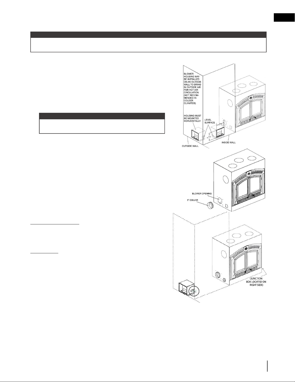
BLOWER INSTALLATION
Consideration should be made for blower location as the closer to the appliance, the greater the air fl ow noise
will be. Blower may be installed on either side of the appliance.
note:
A. Position the blower to an inside or outside wall into a framed
opening 12 3/8” wide by 10 1/2” high (314mm x 267mm).
(Outside wall not recommended in colder climates as cold air
may be drawn into the house even when the blower is off).
The blower housing should be installed onto a level surface
large enough to support the blower assembly. Allow for
fi nishing material when securing the blower housing, as the
grille mounts to the housing.
COLLAR INSTALLATION
B. Determine which side of the appliance the blower is to be
located on. Remove and discard the cover plate and install
the 6” (152mm) collar.
Secure by reaching through the collar and bending the tabs.
Use sealant to ensure that the connection is air tight.
ELECTRICAL CONNECTION
C. Remove the junction box covers on the appliance and the
blower. Removing the junction box cover on the appliance
exposes 4 black, labeled wires:
Appliance Junction Box
Two wires labelled “by-pass” - go to by-pass (summer) switch
(not supplied - overrides the thermally activated switch enabling
the user to run the blower without heat).
IMPORTANT: If the by-pass (summer) switch is not
desired, terminate the wires by attaching wire nuts to
by-pass (summer) switch wire leads separately (do not
connect together).
One wire labelled “blower” - connects to fan-speed control
rheostat and then the fan-speed control connects to the white
blower wire.
One wire labelled “L1” - connects to power (hot lead).
Blower housing may be installed inside a home that has
suffi cient air fl ow.
note:
Loading ...
Loading ...
Loading ...