Loading ...
Loading ...
Loading ...
19
SERVICE AND MAINTENANCE
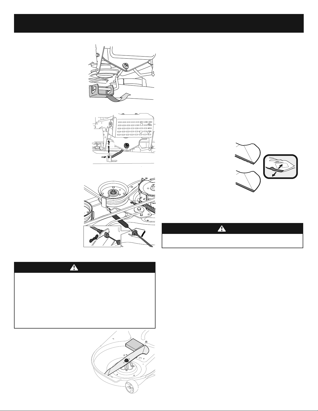
6. Repeat step 5 on the tractor’s right side.
7. Move the deck lift lever into
the top notch on the right
fender to raise the deck lift
arms up and out of the way.
8. On 38” decks, gently slide
the cutting deck toward the
front of the tractor carefully
guiding the hooks on the deck
on the deck off of the deck
stabilizer rod. See Figure 32.
9. On 36”, 42” and 46” decks,
Remove the bow-tie pin (a)
securing the deck stabilizer rod
(b) to the deck. Slide the deck
lift rod from the mounting
weldment on the deck as seen
in Figure 33.
10. Carefully remove the PTO
cable (a) from the rear of the
cutting deck by removing the
bow-tie clip (b) which secures
it. Remove the spring (c) from
the deck idler bracket. See
Figure 34.
11. Gently slide the cutting deck
(from the left side) out from
underneath the tractor.
NOTE: To reinstall the deck after
service, reverse the order of
deck removal steps 1-11 in this
section.
Removing the Blade
WARNING
• Shut the engine off and remove ignition key before removing the cutting
blade(s) for sharpening or replacement. Protect your hands by using
heavy gloves when grasping the blade.
• Periodically inspect the blade and/or spindle for cracks or damage,
especially after you’ve struck a foreign object. Do not operate the tractor
until damaged components are replaced.
• If the cutting edge of the blade has previously been sharpened, or if any
metal separation is present, replace the blades with new ones.
1. Remove the deck from beneath the
tractor, (refer to Deck Removal on page
18) then gently flip the deck over to
expose its underside.
2. Place a block of wood between the
center deck housing baffle and the
cutting blade to act as a stabilizer. See
Figure 35.
3. Remove the hex flange nut that secures
the blade to the spindle assembly. See
Figure 35.
Installing the Blade
1. With the deck removed gently flip the deck over to expose its underside.
2. Line up the hole in the center of the blade with the retainer at the bottom of the
spindle assembly, and the side stamped with “grass-side” or with a part number,
so that it will be facing the ground when with the deck reinstalled and in the
proper operating position.
3. Place a block of wood between the deck housing baffle and the cutting blade to
act as a stabilizer. See Figure 35.
4. Thread on the hex flange nut to secure the blade to the spindle assembly. Use a
torque wrench to tighten the blade spindle hex flange nut to 80-90 ft-lbs (95-122
N-m).
NOTE: When replacing or reinstalling the blade, be sure to install the blade with
the side of the blade marked ‘‘Bottom’’ (or with a part number stamped in it)
facing the ground.
Sharpening the Blade
1. To properly sharpen the cutting
blades, remove equal amounts
of metal from both ends of the
blades along the cutting edges,
parallel to the trailing edge, at
a 25° to 30° angle. Always grind
each cutting blade edge equally
to maintain proper blade balance.
See Figure 36.
2. Test the blade’s balance using a blade balancer. Grind metal from the heavy side
until it balances evenly.
WARNING
A poorly balanced blade will cause excessive vibration, may damage the tractor
and/or result in personal injury.
Figure 32
(a)
(b)
Figure 33
(b)
(b)
(a)
(c)
(b)
Figure 34
Figure 35
Figure 36
Loading ...
Loading ...
Loading ...