Loading ...
Loading ...
Loading ...
15
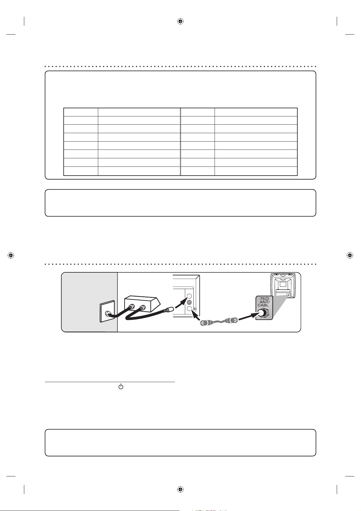
Connection to a cable box or satellite box
Note to the Cable TV System Installer :
This reminder is provided to call the Cable TV system installer’s attention to Article 820-40 of the National Electrical Code,
which provides guidelines for proper grounding - in particular, specifying that the cable ground shall be connected to the
grounding system of the building, as close to the point of cable entry as possible.
DVD/VCR
ANT-IN
ANT-OUT
IN
OUT
E
Cable TV signal
(Cable box or
Satellite box)
(Back of this unit)
RF cable
(supplied)
(Back of TV)
This connection allows you to view or record a scrambled channel. With this connection, channels cannot be changed on this
unit. You can view or record ONLY the channels you have selected on the cable box or the satellite box.
While you are recording, only the recorded channel can be viewed.
If you use the VCR Plus+ programming system, set the Cable/TV channel to 03 or 04 (Cable Box/DBS output channel)
for every VCR Plus+channel in the Channel Line-Up Chart.You must set the Cable Box/DBS to the channel you want
to record; leave the Cable Box/DBS on for the timer recording. (Refer to page 22.)
To select channels of the cable box or satellite box
1) Turn on this unit by pressing [
]. The “POWER” indicator on the front panel will appear. Then, press [CH
+
/
-
] to
select channel 3 or 4 (the same channel as the output channel of the cable box or satellite box).
If noise appears on the TV screen, press [TV/VIDEO] on the remote control.
If you use the channel 4, you will need to change this unit’s RF output to channel 4. Refer to “RF output switch” on
page 100.
2) At the TV, select channel 3 or 4 (the same channel as you have selected at step 1).
3) At the cable box or satellite box, select the channel you want to view or record.
•
•
•
•
After you have completed connections
• Switch the input selector on your TV to an appropriate external input channel (usually near channel 0). Press a
button on the TV’s original remote control that selects an external input channel until the DVD recorder’s picture
appears. Check your TV owner’s manual for details.
Input Mode Names for Common TV Brands (Example)
Admiral
AUX
Panasonic
TV/VIDEO
Curtis Mathis
LINE1, LINE2, 00, 90, 91, 92, 93
RCA
INPUT, TV/VCR, 00, 90, 91, 92, 93
GE
INPUT, TV/VCR, 00, 90, 91, 92, 93
Samsung
TV/VIDEO
Hitachi
INPUT, AUX
Sanyo
VIDEO
JVC
VIDEO, VIDEO 1, VIDEO 2, VIDEO 3
Sharp
00
Kenwood
AUX
Sony
VIDEO1, VIDEO2, VIDEO3
LXI-Series
00
Toshiba
TV/GAME
Magnavox
AUX CHANNEL
Zenith
00
Connection to a TV (cont’d)
To set progressive scan mode, refer to page 90
• This unit is compatible with the Progressive Scan System. The feature provides you with the higher definition
images than the traditional output system does. To utilize this feature, you must set Progressive Scan mode to
“ON”.
E9A90UD_EN.indb 15E9A90UD_EN.indb 15 6/12/2006 4:21:08 PM6/12/2006 4:21:08 PM
Loading ...
Loading ...
Loading ...