Loading ...
Loading ...
Loading ...
FDL (E2.1) 02/2019 page 45/76
Figure 8: Safety thermostat class 2
Function:
The safety thermostat class 2 is functionally and electrically independent of the temperature control device
and turns off the chamber at all poles.
When the control knob (2) is set to the end stop (position 10), the safety thermostat class 2 acts as a
chamber protection device. If it is set somewhat higher than the set-point temperature selected on the
controller, it acts as a material protection device.
When the safety device has turned off the chamber, identifiable by the red alarm lamp (2a) lighting up,
proceed as follows:
• Disconnect the chamber from the power supply.
• Have the cause of the fault examined and rectified by a technician.
• Release safety thermostat class 2 by pressing reset button (2b).
• Restart the chamber as described in chap. 5.
Setting:
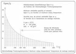
The diagram given in chap. 2.3 indicates the drying temperature to be set on the controller in relation to
the quantity of the introduced solvents. This must not be exceeded. For this reason, adjust the tempera-
ture safety device according to the selected set-point.
DANGER
Excessive drying temperature.
Danger of explosion.
Danger of death.
∅ Do NOT exceed the maximum drying temperature for the solvent quantity.
To check at which temperature the safety device activates, turn on the oven and set the required nominal
value on the temperature controller.
The scale division from 1 to 10 corresponds to the temperature range from 30 °C / 86 °F up to 320 °C /
608 °F and serves as a setting aid.
• Detach the plastic cover over the temperature safety device class 2
(2) with a suitable Phillips screwdriver.
•
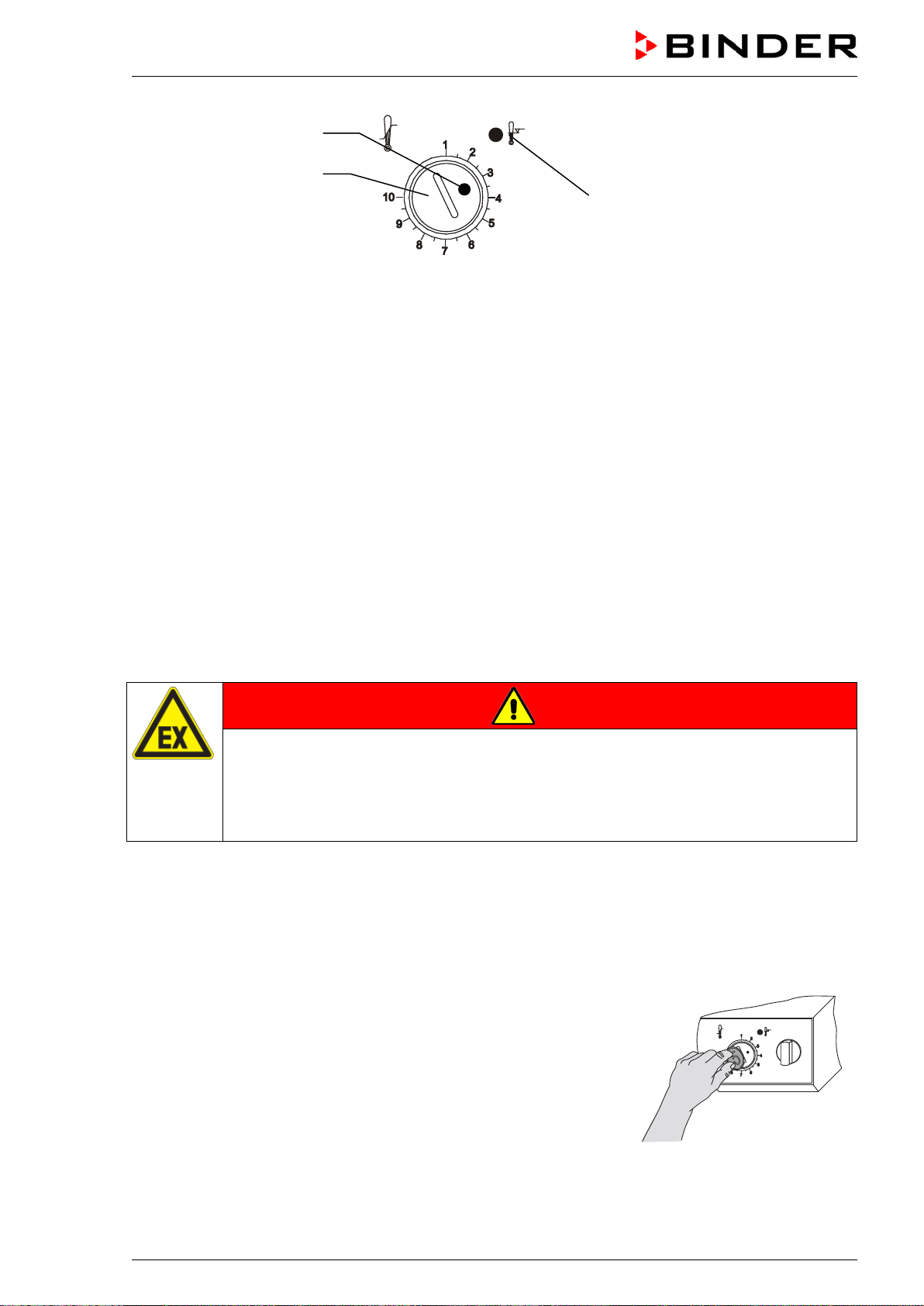
Turn the control knob (2) of the safety device using a coin to its
end-stop (position 10) (chamber protection).
• When the set point is reached, turn back the control knob (2) until
its trip point (turn it counter-clockwise) is reached.
• The red alarm lamp (2a) lighting up identifies the trip point; and the
reset button (2b) pops out.
• The optimum setting of the safety device is obtained by turning the
knob clockwise by approx. one graduation mark on the scale.
• Push the reset button (2b) in again.
• Restore the plastic cover to prevent misadjusting
Figure 9: Setting the safety
device class 2
(2)
(2a)
(2b)
Loading ...
Loading ...
Loading ...