Owner's Guide Tools - Home Improvement
INTRODUCTION
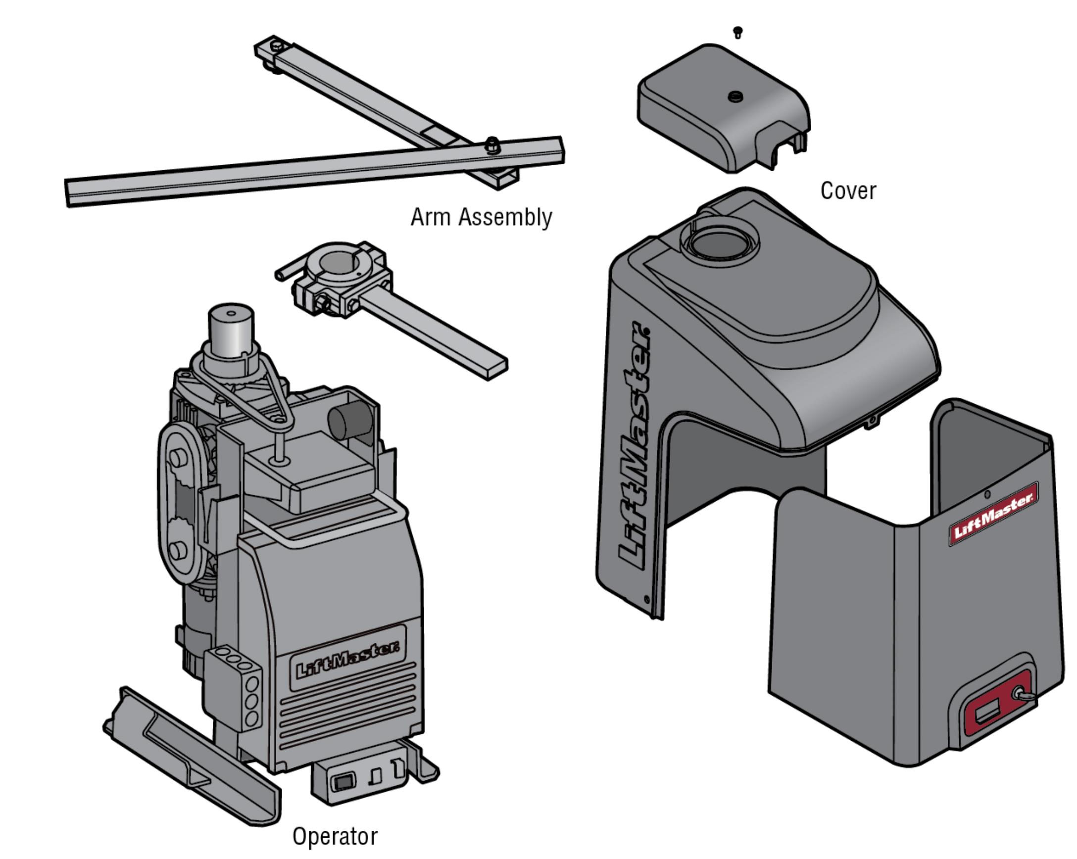
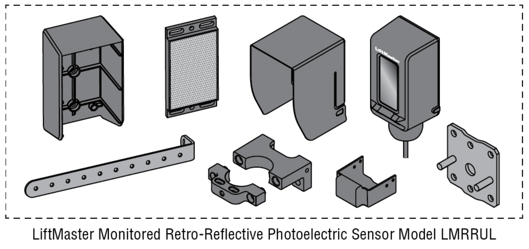
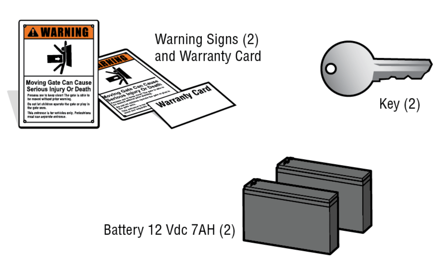
Carton Inventory
NOT SHOWN: Documentation packet and hardware bag
PROGRAMMING
Remote Controls (Not Provided)
A total of 50 Security+ 2.0 ® remote controls or KPW250 keypads and 2 keyless entries (1 PIN for each keyless entry) can be programmed to the operator. When programming a third keyless entry to the operator, the first keyless entry will be erased to allow the third keyless entry to be programmed. When the operator’s memory is full it will exit the programming mode and the remote control will not be programmed. The memory will need to be erased before programming any additional remote controls.
NOTE: If installing an 86LM to extend the range of the remote controls DO NOT straighten the antenna.
There are 3 different options for programming the remote control depending on how you would like the remote control to function. Choose a programming option:
| OPTION |
DESCRIPTION |
PROGRAMMING STEPS |
|
Single button as OPEN only
|
Program a single button on the remote control for open only. The Timer-to-Close can be set to close the gate.
|
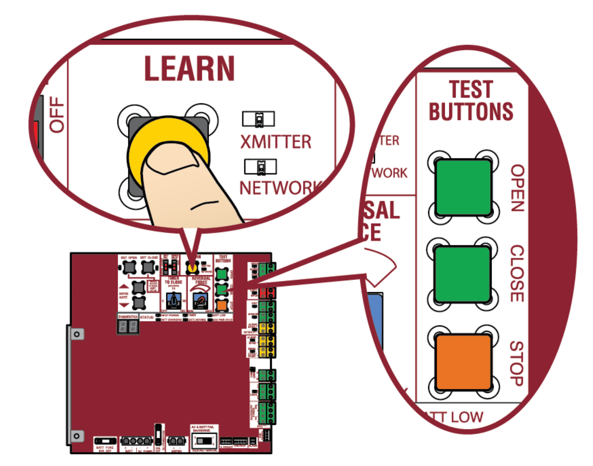
- Press and release the LEARN button (operator will beep and green XMITTER LED will light).
NOTE: The operator will time out of programming mode after 30 seconds.
- Press the OPEN button.
- Press the remote control button that you would like to program.
|
|
Single button (SBC) as OPEN, CLOSE, and STOP
|
Program one remote control button as an open, close, and stop.
|
- Press and release the LEARN button (operator will beep and green XMITTER LED will light).
NOTE: The operator will time out of programming mode after 30 seconds.
- Press the remote control button that you would like to program.
|
|
Three separate buttons as OPEN, CLOSE, and STOP
|
Program each remote control button as an open, close, and stop.
|
- Press and release the LEARN button (operator will beep and green XMITTER LED will light).
NOTE: The operator will time out of programming mode after 30seconds.
- Press the OPEN, CLOSE, or STOP button, depending on the desired function.
- Press the remote control button that you would like to program.
|
The operator will automatically exit learn mode (operator will beep and green XMITTER LED will go out) if programming is successful. To program additional Security+ 2.0 ® remote controls or remote control buttons, repeat the programming steps above.
Entering programming mode using external reset button or 3-button control station:
- Make sure gate/door is closed.
- Give the operator an OPEN command.
- Within 30 seconds, when the gate/door is at the open limit press and release the RESET/STOP button twice to put the operator into programming mode. NOTE: The operator will time out of programming mode after 30 seconds.
NOTICE: This device complies with Part 15 of the FCC rules and Industry Canada’s license-exempt RSSs. Operation is subject to the following two conditions: (1) this device may not cause harmful interference, and (2) this device must accept any interference received, including interference that may cause undesired operation.
Any changes or modifications not expressly approved by the party responsible for compliance could void the user’s authority to operate the equipment.
This device must be installed to ensure a minimum 20 cm (8 in.) distance is maintained between users/bystanders and device.
This device has been tested and found to comply with the limits for a Class B digital device, pursuant to part 15 of the FCC rules and Industry Canada ICES standard. These limits are designed to provide reasonable protection against harmful interference in a residential installation. This equipment generates, uses and can radiate radio frequency energy and, if not installed and used in accordance with the instructions, may cause harmful interference to radio communications. However, there is no guarantee that interference will not occur in a particular installation. If this equipment does cause harmful interference to radio or television reception, which can be determined by turning the equipment off and on, the user is encouraged to try to correct the interference by one or more of the following measures:
- Reorient or relocate the receiving antenna.
- Increase the separation between the equipment and receiver.
- Connect the equipment into an outlet on a circuit different from that to which the receiver is connected.
- Consult the dealer or an experienced radio/TV technician for help.
LiftMaster Internet Gateway (not provided)
To program the operator to the LiftMaster Internet Gateway:
Using the learn button on the opertaor's control board
- Connect the ethernet cable to the LiftMaster Internet Gateway and the router.
- Connect power to the LiftMaster Internet Gateway.
- Create an online account by visiting www.myliftmaster.com.
- Register the LiftMaster Internet Gateway.
- Use an internet enabled computer or smartphone to add devices. The LiftMaster Internet Gateway will stay in learn mode for three minutes.
- Press the Learn button twice on the primary operator (the operator will beep as it enters learn mode). The LiftMaster Internet Gateway will pair to the operator if it is within range and the operator will beep if programming is successful.
Using the reset button on the operator
- Connect the ethernet cable to the LiftMaster Internet Gateway and the router.
- Connect power to the LiftMaster Internet Gateway.
- Create an online account by visiting www.myliftmaster.com.
- Register the LiftMaster Internet Gateway.
- Use an internet enabled computer or smartphone to add devices. The LiftMaster Internet Gateway will stay in learn mode for three minutes.
- Ensure gate is closed.
- Give the operator an OPEN command.
- Within 30 seconds, when the gate is at the open limit press and release the reset button 3 times (on primary gate) to put primary operator into High Band Learn Mode (the operator will beep as it enters learn mode). The LiftMaster Internet Gateway will pair to the operator if it is within range and the operator will beep if programming is successful.
The status as shown by the LiftMaster Internet Gateway app will be either “open” or “closed”. The gate operator can then be controlled through the LiftMaster Internet Gateway app.
Erase All Codes
- Press and release the LEARN button (operator will beep and green XMITTER LED will light).
- Press and hold the LEARN button again until the green XMITTER LED flashes and then release the button (approximately 6 seconds). All remote control codes are now erased.
Erase Limits
- To erase the limits, press and hold the SET OPEN and SET CLOSE buttons simultaneously (5 seconds) until both the SET OPEN and SET CLOSE LEDs blink rapidly and the operator beeps.
- Release the buttons and the SET OPEN and SET CLOSE LEDs will blink slowly indicating the limits will need to be set.
Constant Pressure Override (CPO)
Constant Pressure Override is for use with KPW5 and KPW250 keypads (not provided). The KPW5/KPW250 wireless commercial keypads are security keypads and can only be programmed to ONE gate operator (see the KPW5/KPW250 manual for complete programming instructions).
The Constant Pressure Override feature is intended to temporarily override a fault in the entrapment protection system, in order to operate the gate until the external entrapment protection device is realigned or repaired. Use the feature only in line of sight of the gate when no obstructions to travel are present. External entrapment protection devices include LiftMaster monitored photoelectric sensors and LiftMaster monitored wired and wireless edge sensors. Be sure to repair or replace these devices promptly if they are not working properly.
To use Constant Pressure Override:
- Enter a valid 4-digit PIN.
- Press and hold # for 5 seconds to enter CPO. Continue to hold # to keep the operator in motion. A continuous tone will sound until limit is met and/or # is released.
- The operator will stop when either the operator reaches a limit or the user releases #.
Gate Hold Open Feature
The gate hold open feature will disable the timer and keep the gate at the open limit. The gate hold open feature can be activated through the Reset Button as described on page 30 or through the KPW5 and KPW250 keypads (not provided).
To use the gate hold open feature:
- Enter a valid 4-digit PIN when the gate is at the Open Limit and the timer is running
- The Operator will chirp indicating the timer is canceled.
To restart the gate:
- Re-enter the 4-digit PIN
- Activate a Hard input or a programmed remote
To Remove and Erase Monitored Entrapment Protection Devices
- Remove the entrapment protection device wires from the terminal block.
- Press and release the SET OPEN and SET CLOSE buttons simultaneously. The SET OPEN and SET CLOSE LEDs will turn on (entering learn limit mode).
- Press and release both SET OPEN and SET CLOSE buttons again to turn off the SET OPEN and SET CLOSE LEDs (exiting learn limit mode).
OPERATION
Gate operator setup examples
The following are example setups for the gate operator. Your specific site requirements may be different. Always setup the operator system to the site requirements, including all necessary entrapment protection devices.
RESIDENTIAL: One to four residential homes sharing a gated entrance/exit, allowing vehicle access trumps security concerns
COMMERCIAL/GENERAL ACCESS: A residential community (more than four homes) having one or more gated entrances/exits, allowing vehicle access trumps security concerns
COMMERCIAL: Business site where security (gate closed) is important
INDUSTRIAL: Large business site where security is required
| SETTING |
RESIDENTIAL |
COMMERCIAL/GENERAL ACCESS |
COMMERCIAL |
INDUSTRIAL |
|
Quick Close switch setting
|
Normally set to OFF. Normal gate close (timer or control).
|
Normally set to OFF. Normal gate close (timer or control).
|
Normally set to OFF. Normal gate close (timer or control).
|
Set to ON, so that gate closes immediately after vehicle passes CLOSE EYES/Interrupt loop.
|
|
AC Fail Open switch setting
|
Normally set to BATT. Run on battery if AC power fails.
|
Normally set to BATT. For local jurisdiction requirement, set to OPEN so that the gate will open approximately 15 seconds after AC power fail.
|
Normally set to BATT. Run on battery if AC power fails.
|
Normally set to BATT. Run on battery if AC power fails.
|
|
Low Battery switch setting
|
Normally set to OPEN. If powered from battery and battery is low, gate automatically opens and stays open.
|
Normally set to OPEN. If powered from battery and battery is low, gate automatically opens and stays open.
|
Normally set to CLOSE. If powered from battery and battery is low, gate stays closed.
|
Normally set to CLOSE. If powered from battery and battery is low, gate stays closed.
|
|
Anti-Tail switch setting
|
Normally set to OFF. CLOSE EYES/Interrupt loop reverses a closing gate.
|
Normally set to OFF. CLOSE EYES/Interrupt loop reverses a closing gate.
|
Set to ON. In attempt to prevent vehicle tail-gating, CLOSE EYES/ Interrupt loop pauses a closing gate.
|
Set to ON. In attempt to prevent vehicle tail-gating, CLOSE EYES/ Interrupt loop pauses a closing gate.
|
|
Bipart Delay switch setting
|
For DUAL-GATE site, set to ON for gate that delays upon opening.
|
For DUAL-GATE site, set to ON for gate that delays upon opening.
|
For DUAL-GATE site, set to ON for gate that delays upon opening.
|
For DUAL-GATE site, set to ON for gate that delays upon opening.
|
|
Aux Relay Out – Open Limit Switch
|
Typically not required.
|
Use with SAMS (Sequence Access Management System).
|
- Use with SAMS (Sequence Access Management System).
- Connect “Gate Open” indicator (e.g.light).
|
- Use with SAMS (Sequence Access Management System).
- Connect “Gate Open” indicator (e.g.light).
|
|
Aux Relay Out – Close Limit Switch
|
Typically not required.
|
Typically not required.
|
Connect “Gate Close/Secure” indicator (e.g. light).
|
Connect “Gate Close/Secure” indicator (e.g. light).
|
|
Aux Relay Out – Gate Motion
|
Attach alert signal (audible or visual alert system).
|
Attach alert signal (audible or visual alert system).
|
Attach alert signal (audible or visual alert system).
|
Attach alert signal (audible or visualalert system).
|
|
Aux Relay Out – Pre-Motion Delay
|
Attach alert signal (audible or visual alert system).
|
Attach alert signal (audible or visual alert system).
|
Attach alert signal (audible or visual alert system).
|
Attach alert signal (audible or visualalert system).
|
|
Aux Relay Out – Power
|
Attach visual alert to know when system is charging batteries (i.e. not running on batteries).
|
Attach visual alert to know when system is charging batteries (i.e. not running on batteries).
|
Attach visual alert to know when system is charging batteries (i.e. not running on batteries).
|
Attach visual alert to know when system is charging batteries (i.e. not running on batteries).
|
|
Cycle Quantity Feedback
|
Use during servicing only to determine operator cycles.
|
Use during servicing only to determine operator cycles.
|
Use during servicing only to determine operator cycles.
|
Use during servicing only to determine operator cycles.
|
|
Fire Dept Open Input
|
Typically not required.
|
Connect emergency access system (Knox box switch, SOS system, etc.).
|
Typically not required.
|
Typically not required.
|
|
Heater Accessory (Model HTR)
|
The heater keeps the gearbox and batteries at a suitable temperature when the outside temperature is below -4°F. The thermostat MUST be set between 45°F and 60°F to ensure proper gate operation.
|
The heater keeps the gear \box and batteries at a suitable temperature when the outside temperature is below -4°F. The thermostat MUST be set between 45°F and 60°F to ensure proper gate operation.
|
The heater keeps the gearbox and batteries at a suitable temperature when the outside temperature is below -4°F. The thermostat MUST be set between 45°F and 60°F to ensure proper gate operation.
|
The heater keeps the gearbox and batteries at a suitable temperature when the outside temperature is below -4°F. The thermostat MUST be set between 45°F and 60°F to ensure proper gate operation.
|
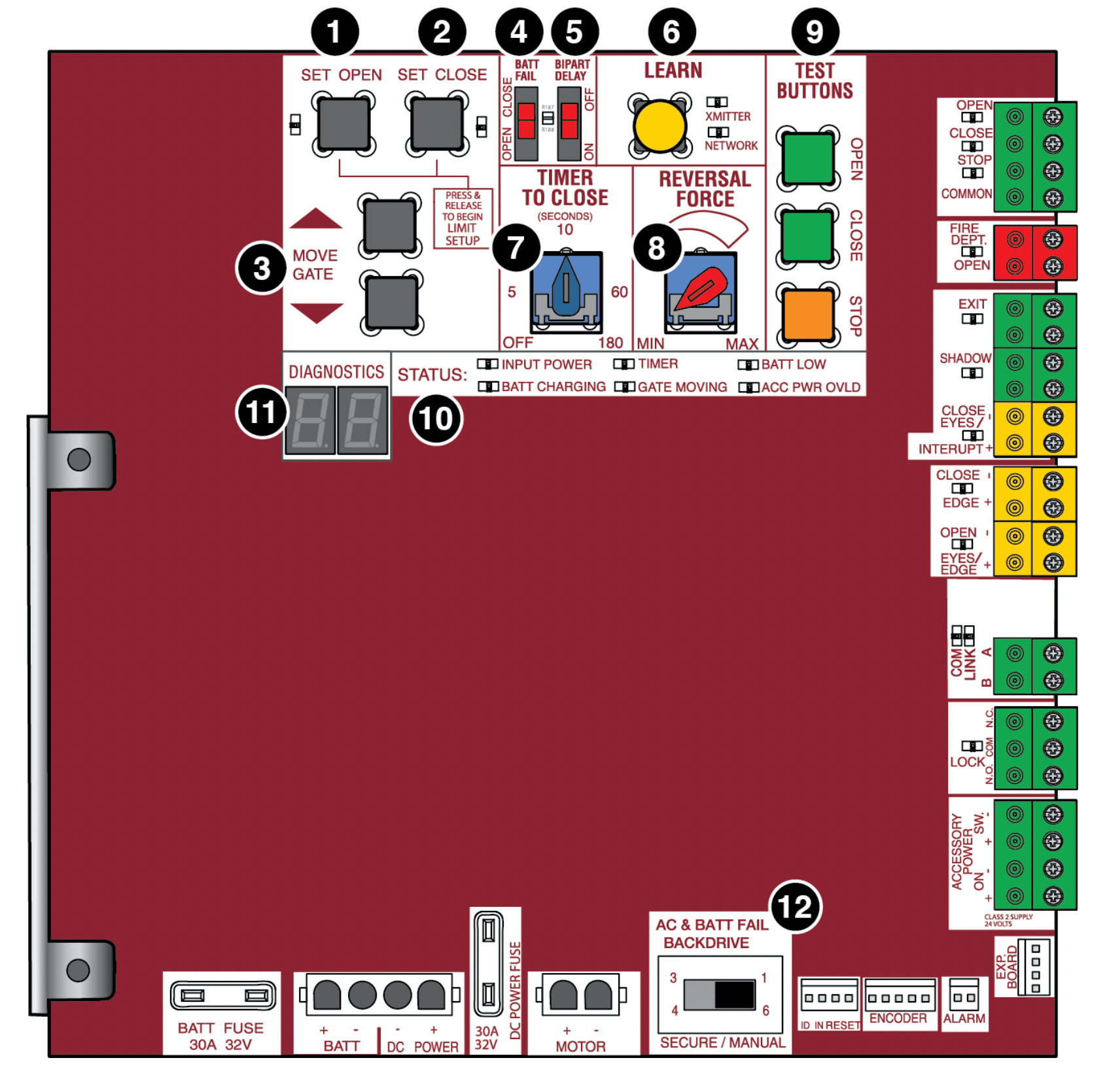
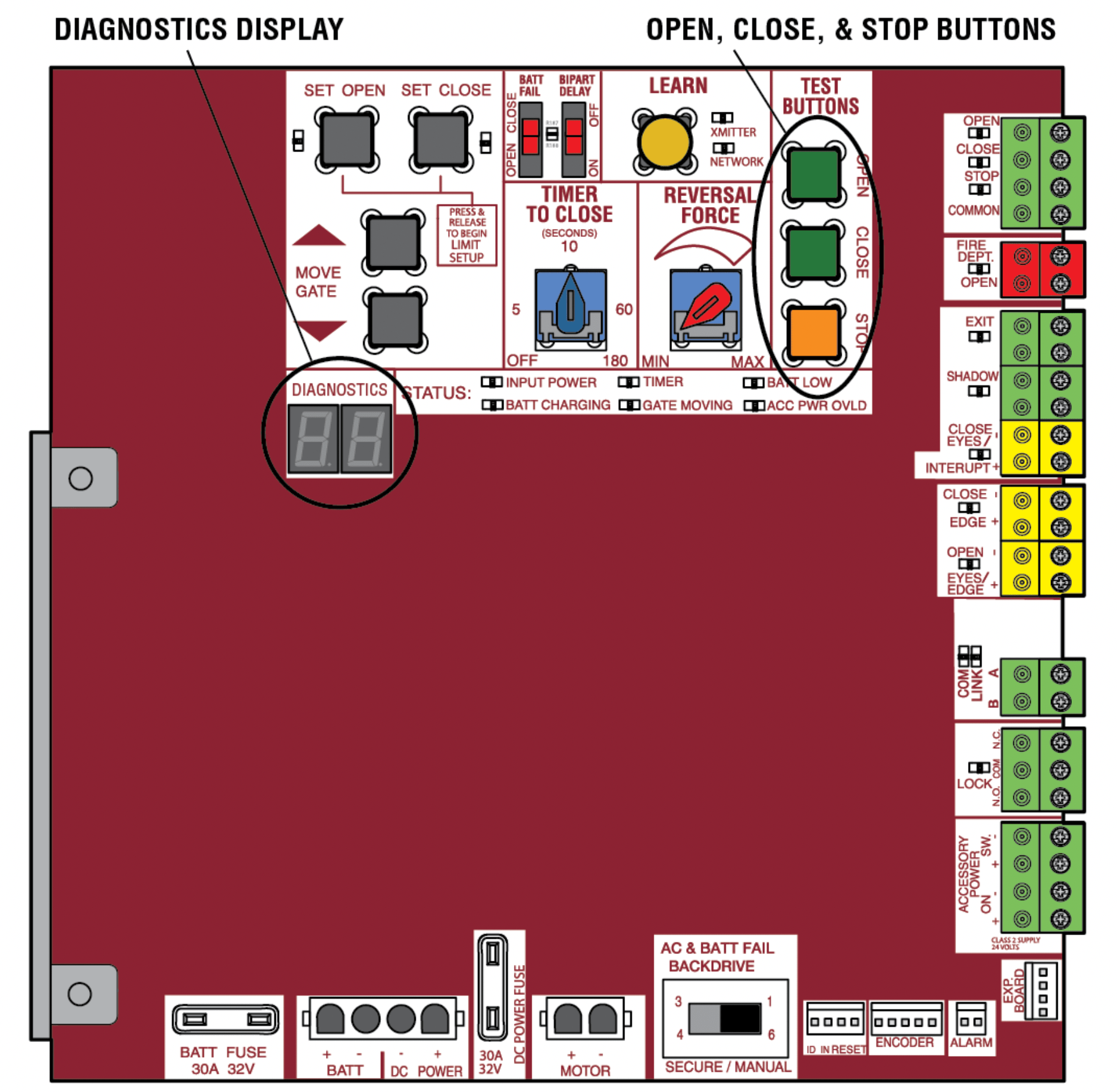
Control Board Overview
- SET OPEN Button: The SET OPEN button sets the OPEN limit. See Adjust Limits section.
- SET CLOSE Button: The SET CLOSE button sets the CLOSE limit. See Adjust Limits section.
- MOVE GATE Buttons: The MOVE GATE buttons will either open or close the gate when the operator is in Limit setting mode. See Adjust Limits section.
- BATT FAIL:
When AC power is OFF and battery voltage is critically low the gate will latch at a limit until AC power is restored or batteries voltage increases.
Option select switch set to OPEN forces gate to automatically open and then latch at the OPEN limit until AC power is restored or battery voltage increases.
Option select switch set to CLOSE forces gate to latch at CLOSE limit if at CLOSE limit or on next CLOSE command until AC power restored or battery voltage increases.
Constant pressure on a hard command input overrides to open or close the gate.
Critically low battery is less than 23 V
- BIPART DELAY Switch: The LOCK/BIPART DELAY switch is used only for dual gates. See Bipart Delay section.
- LEARN Button: The LEARN button is for programming remote controls and the network.
- TIMER-TO-CLOSE dial: The TIMER-TO-CLOSE (TTC) dial can be set to automatically close the gate after a specified time period. The TTC is factory set to OFF. If the TTC is set to the OFF position, then the gate will remain open until the operator receives another command from a control. Rotate the TIMER-TO-CLOSE dial to the desired setting. The range is 0 to 180 seconds, 0 seconds is OFF. NOTE: Any radio command, single button control, or CLOSE command on the control board prior to the TTC expiring will close the gate. The TTC is reset by any signals from the open controls, loops, close edges, and close photoelectric sensors (IR’s).
- REVERSAL FORCE dial: The REVERSAL FORCE dial fine tunes the force. See Force Adjustment section.
- TEST BUTTONS: The TEST BUTTONS will operate the gate (OPEN, STOP and CLOSE).
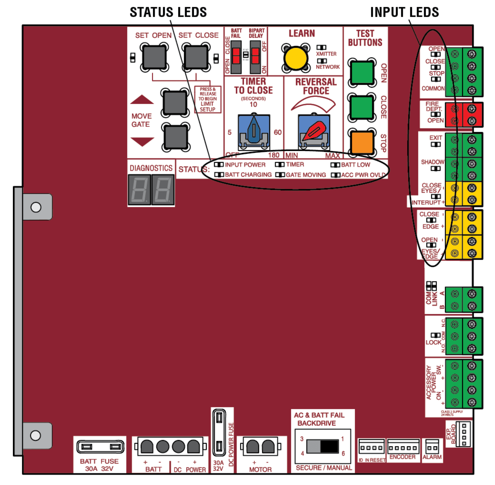
- STATUS LEDs: The STATUS LEDs indicate the status of the operator. See Status LED Chart in the Troubleshooting section.
- DIAGNOSTICS Display: The diagnostics display will show the operator type, firmware version, and codes. The operator type will display as "SG" followed by a "24" which indicates the operator type as CSW24UL. The firmware version will show after the operator type, example "1.2".
- BACKDRIVE Switch: Set to MANUAL will allow the gate to be manually pushed open or closed if there is a loss of AC and battery power. Set to SECURE makes the gate difficult to push open or closed if there is a loss of AC and battery power.
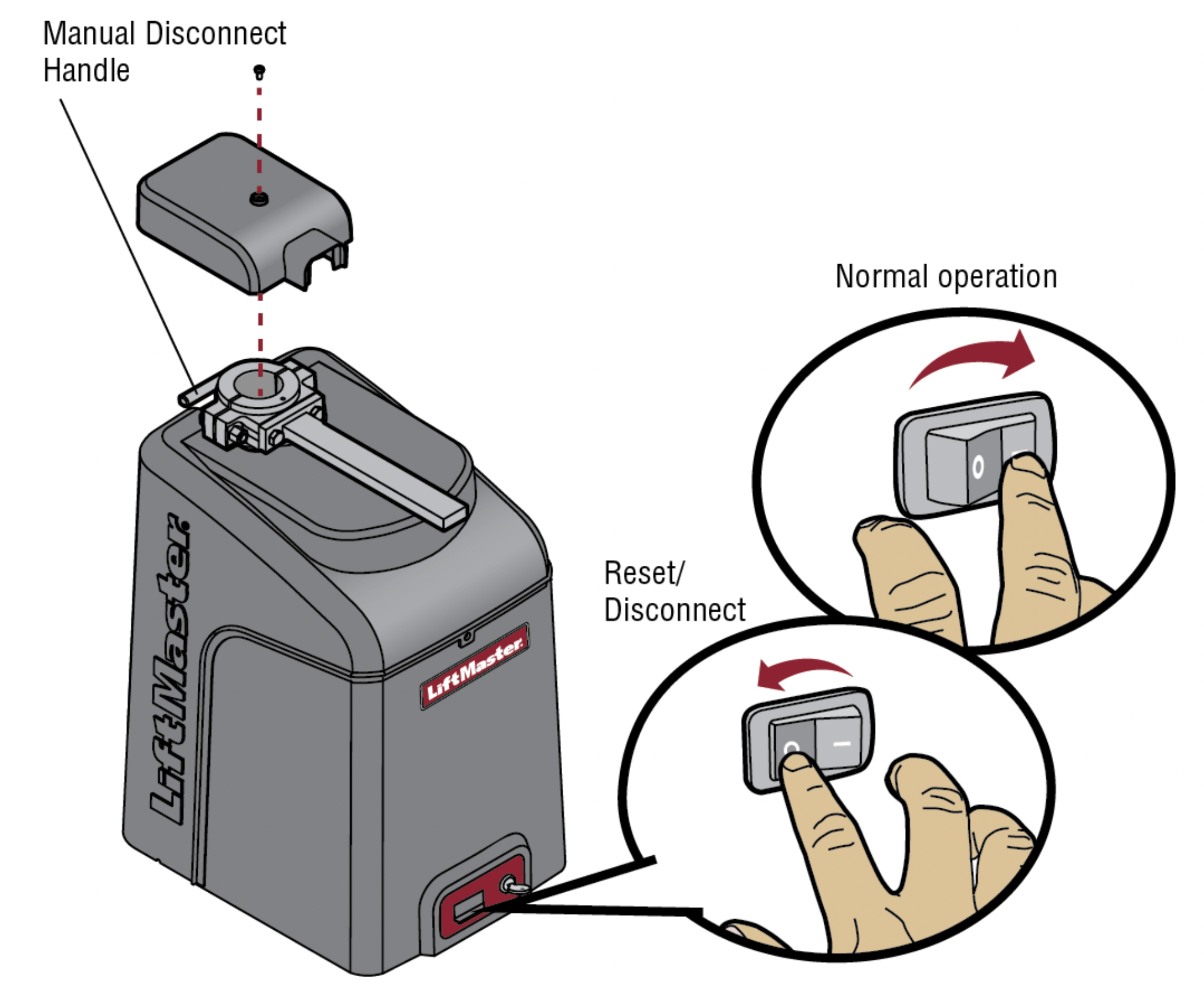
Manual Disconnect
Press the reset switch to RESET/DISCONNECT. Release the handle on the operator arm to allow the gate to be opened and closed manually. On a dual gate application the handle must be released on both operators. To resume normal function tighten the handle by pushing it down.
Reset Switch
The reset switch is located on the front of the operator and serves several functions.
Toggling the reset switch will stop a moving gate during a normal open/ close cycle, like a stop button. The operator does not need to be reset after doing this. The reset switch will disable the gate in the present position and will energize the solenoid lock for two minutes and disable the maglock for two minutes.
Operator Alarm
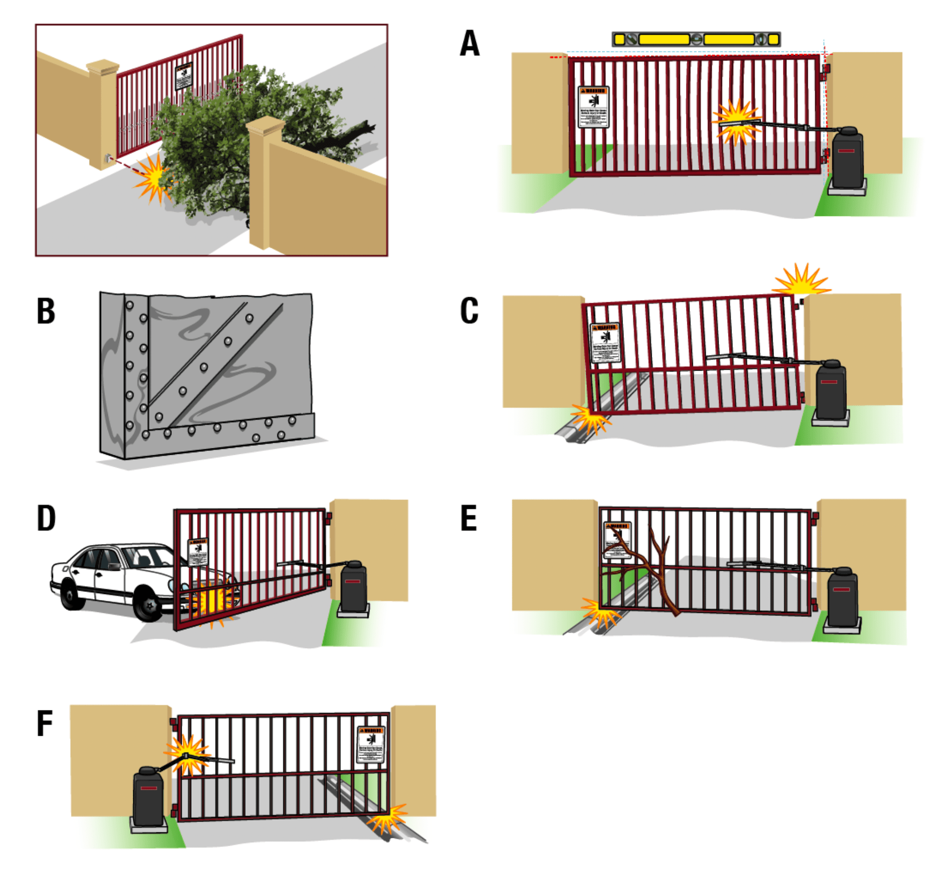
If a contact sensor detects an obstruction twice consecutively the alarm will sound (up to 5 minutes) and the operator will need to be reset. When the inherent force of the operator (RPM/current sensor) detects the following (twice consecutively) the alarm will sound (up to 5 minutes) and the operator will need to be reset.
A. The operator arm or gate is incorrectly installed.
B. The gate does not meet specifications.
C. Gate hinges are too tight or broken and the gate is not moving freely.
D. The gate is moving and a car pushes the gate.
E. A foreign object is on the gate frame while the gate is moving.
F. The gate hits the driveway or curb and gets stuck or bent in an awkward position.
Remove any obstructions. Press the reset button to shut off the alarm and reset the operator. After the operator is reset, normal functions will resume.
The operator alarm will beep 3 times with a command if the battery is low.
Remote control
Single Button Control (SBC) Functionality
Once the remote control has been programmed the operator will operate as follows:
When gate is in the closed position, activation of the remote control button will open the gate. During the open cycle another activation of the remote control will stop the gate and the next activation of the remote control will close the gate.
When the gate is in the open position, activation of the remote control button will close the gate. If the remote control is activated while the gate is closing, the gate will stop and the next activation will open the gate.
ACCESSORY WIRING
All control wiring used to connect external devices to Class 2 circuits of the operator must be (QPTZ) Power-Limited Circuit Cables, Type CL2, CL2P, CL2R, or CL2X or other cable with equivalent or better electrical, mechanical, and flammability ratings.
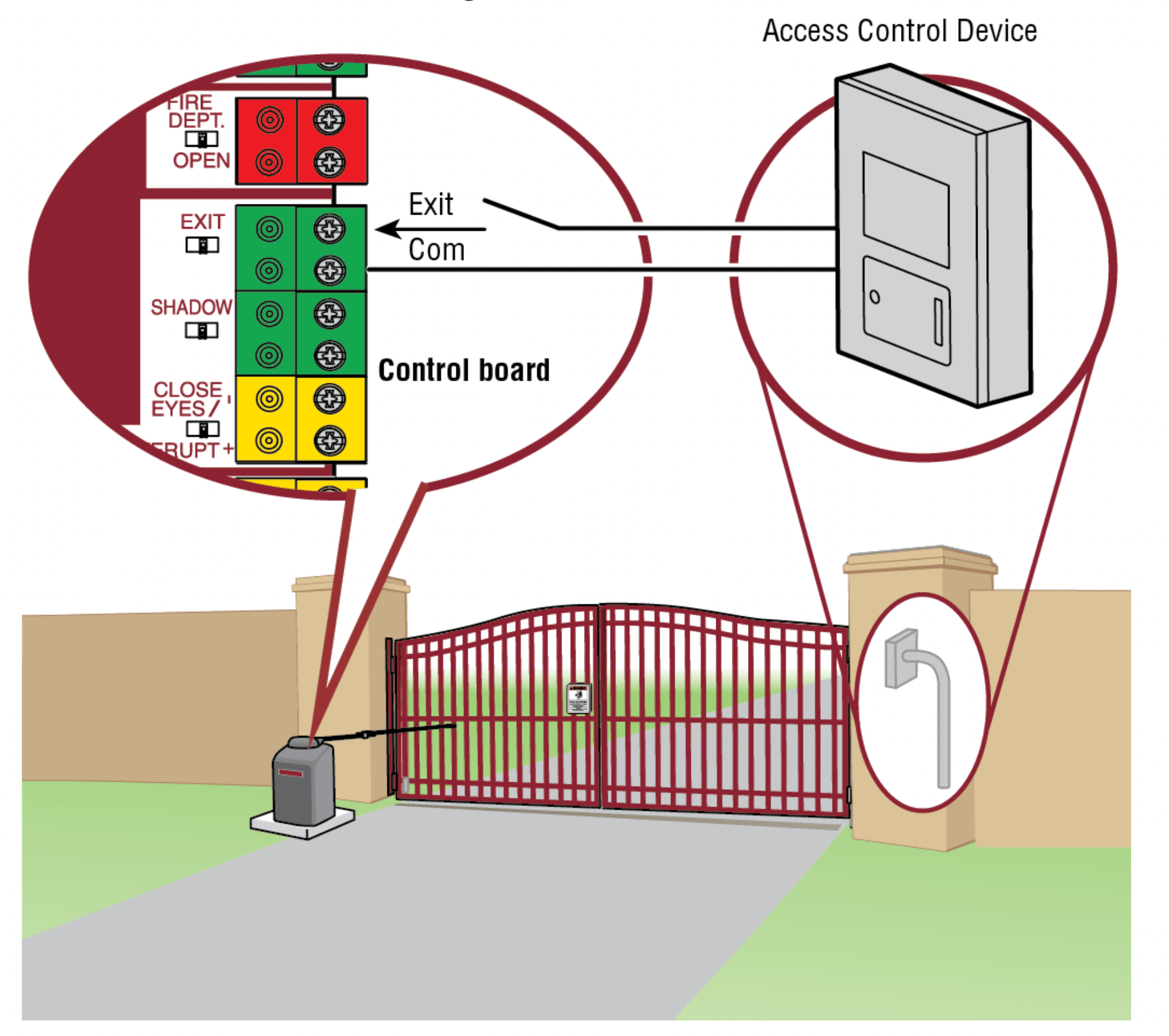
External control devices
Access control device wiring
Loop wiring
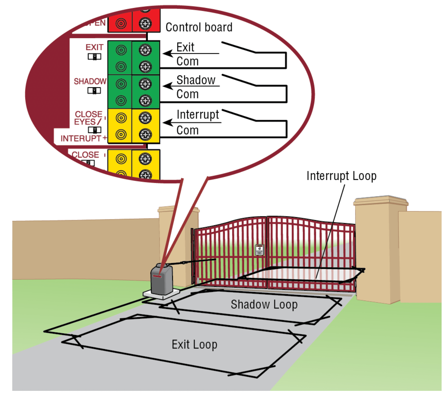
EXIT (2 Terminals)
This input is a soft open command (maintained switch does not override external safeties and does not reset alarm condition). Used for exit probe, telephone entry, external exit loop detector, or any device that would command the gate to open.
- Opens a closing gate and holds open an open gate, if maintained, pauses Timer-to-Close at OPEN limit.
SHADOW (2 Terminals)
This input is used for external shadow loop detector when loop is positioned under the swing of the gate.
- Holds open gate at open limit
- Only active when the gate is at the OPEN limit, disregarded at all other times
- Pauses Timer-to-Close at OPEN limit
INTERRUPT (2 Terminals)
This input is used for photoelectric sensors and external interrupt loop detector when loop is on the outside of the gate.
- Holds open gate at open limit
- Stops and reverses a closing gate to open limit
- Pauses Timer-to-Close at OPEN limit, activates quick close and antitailgate features when enabled on the expansion board
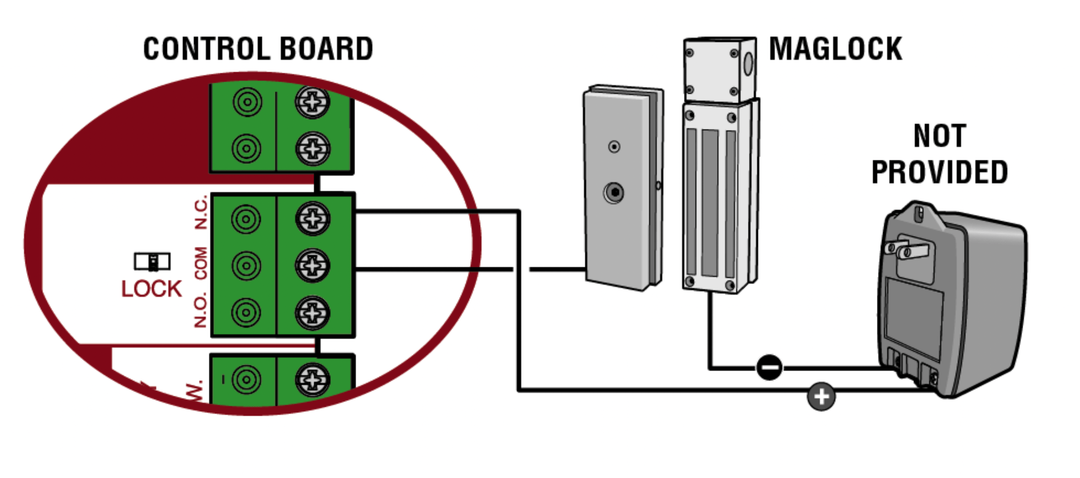
Locks
Maglock (2 Terminals, N.C. and COM)
Relay contact output, Normally - closed (N.C.) output for maglocks. Relay activates prior to motor activation and during motor run. Relay is off when motor is off.
Miscellaneous wiring
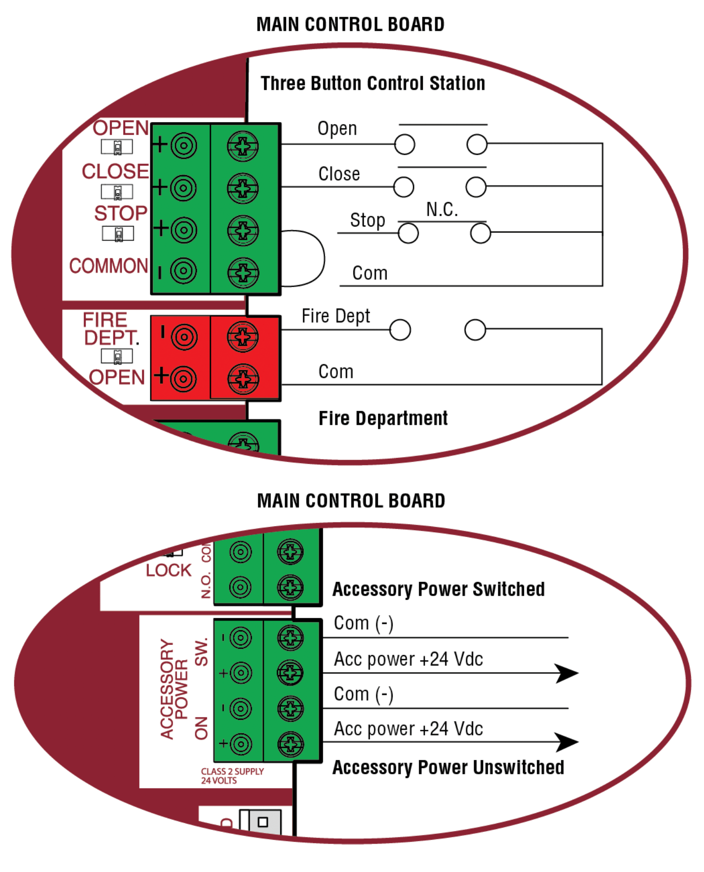
Three button control station (4 Terminals)
- OPEN and COM: Opens a closed gate. Hard open (maintained switch overrides external safeties and resets alarm condition). If maintained, pauses Timer-to-Close at OPEN limit. Opens a closing gate and holds open an open gate (within line-of-sight).
- CLOSE and COM: Closes an open gate. Hard close (maintained switch overrides external safeties and resets alarm condition within line-of-sight)
- STOP and COM: Stops a moving gate. Hard stop (maintained switch overrides Open and Close commands and resets alarm condition). If maintained, pauses Timer-to-Close at OPEN limit. Overrides Open and Close commands (within line-of-sight).
Fire department open input (2 Terminals)
Acts as hard open.
Maintained input overrides (ignores) external safeties (photoelectric sensor and edge), pauses Timer-to-Close momentary input logic as single button control and safeties remain active, re-enables Timer-to-Close.
Accessory power 24 VDC, MAX 500 mA (4 Terminals)
- SWITCHED: Switched ON with gate motion and at the open limit when Timer-to-Close is active. Turns off 5 seconds after motion.
- UNSWITCHED: 24 Vdc voltage out to power accessories, always ON.
EXPANSION BOARD
CAUTION: To AVOID damaging the circuit board, relays or accessories, DO NOT connect more than 42 Vdc (32 Vac) to the AUX relay contact terminal blocks.
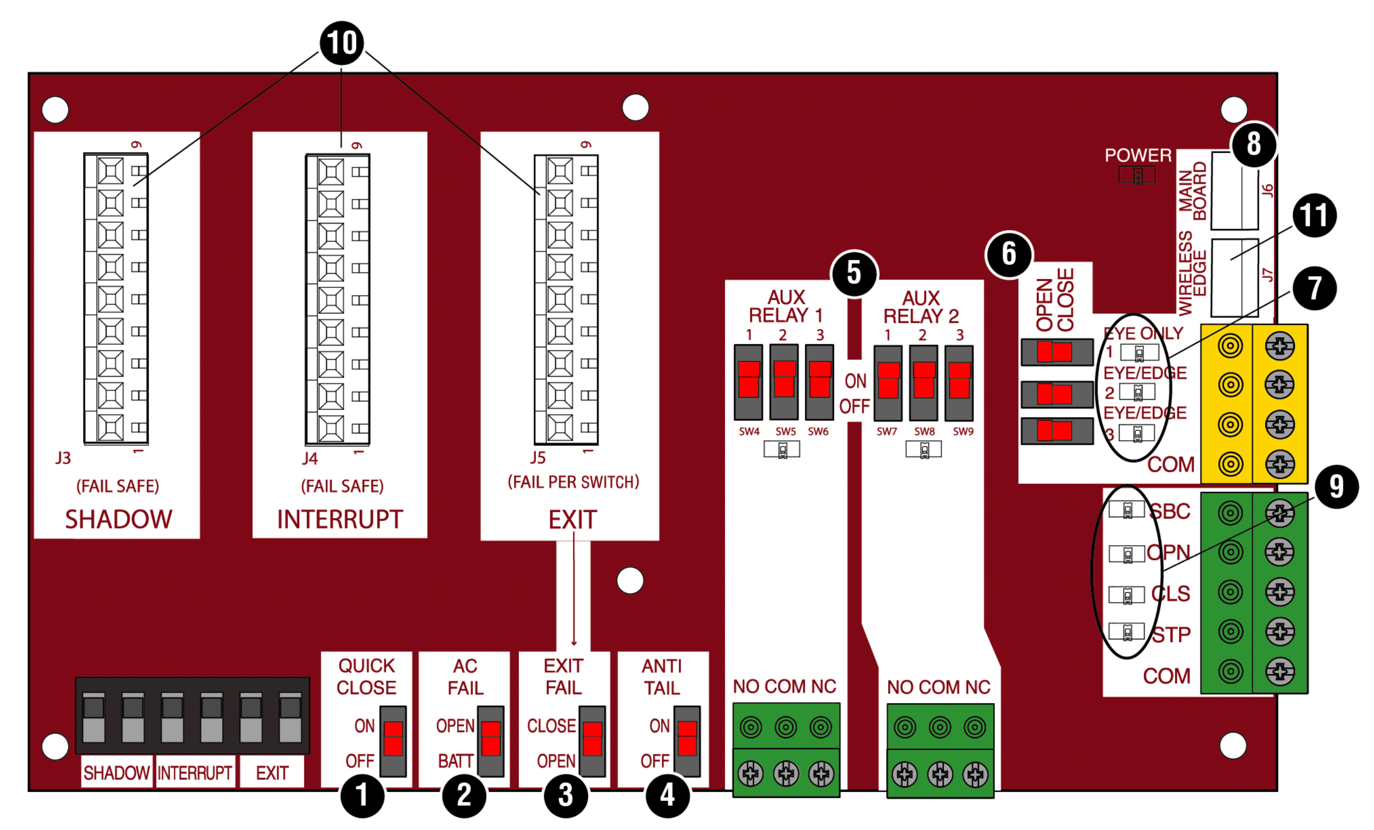
Expansion board overview
- QUICK CLOSE switch:
OFF: No change to the gate's normal operation.
ON: When CLOSE EYES/Interrupt loop is deactivated it causes an opening or a stopped gate to close (ignores the Timer-to-Close).
- AC FAIL switch:
OPEN: Loss of AC power will cause the gate to open approximately 15 seconds after AC power fail and remain OPEN until AC power is restored (enabling the Timer-to-Close).
BATT: With loss of AC power, gate will remain in present position and operator is powered from batteries.
- EXIT FAIL switch:
When set to OPEN, if the EXIT plug-in loop detector (Model LOOPDETLM) detects a fault, then the gate will open and remain open until fault is cleared. When set to CLOSE, then plug-in EXIT loop detector faults are ignored (EXIT loop is faulted and inoperative).
- ANTI-TAIL switch:
OFF: When CLOSE EYES/Interrupt loop is activated it causes a closing gate to stop and reverse.
ON: When CLOSE EYES/Interrupt loop is activated it causes a closing gate to pause. Once the vehicle is clear the gate will continue to close.
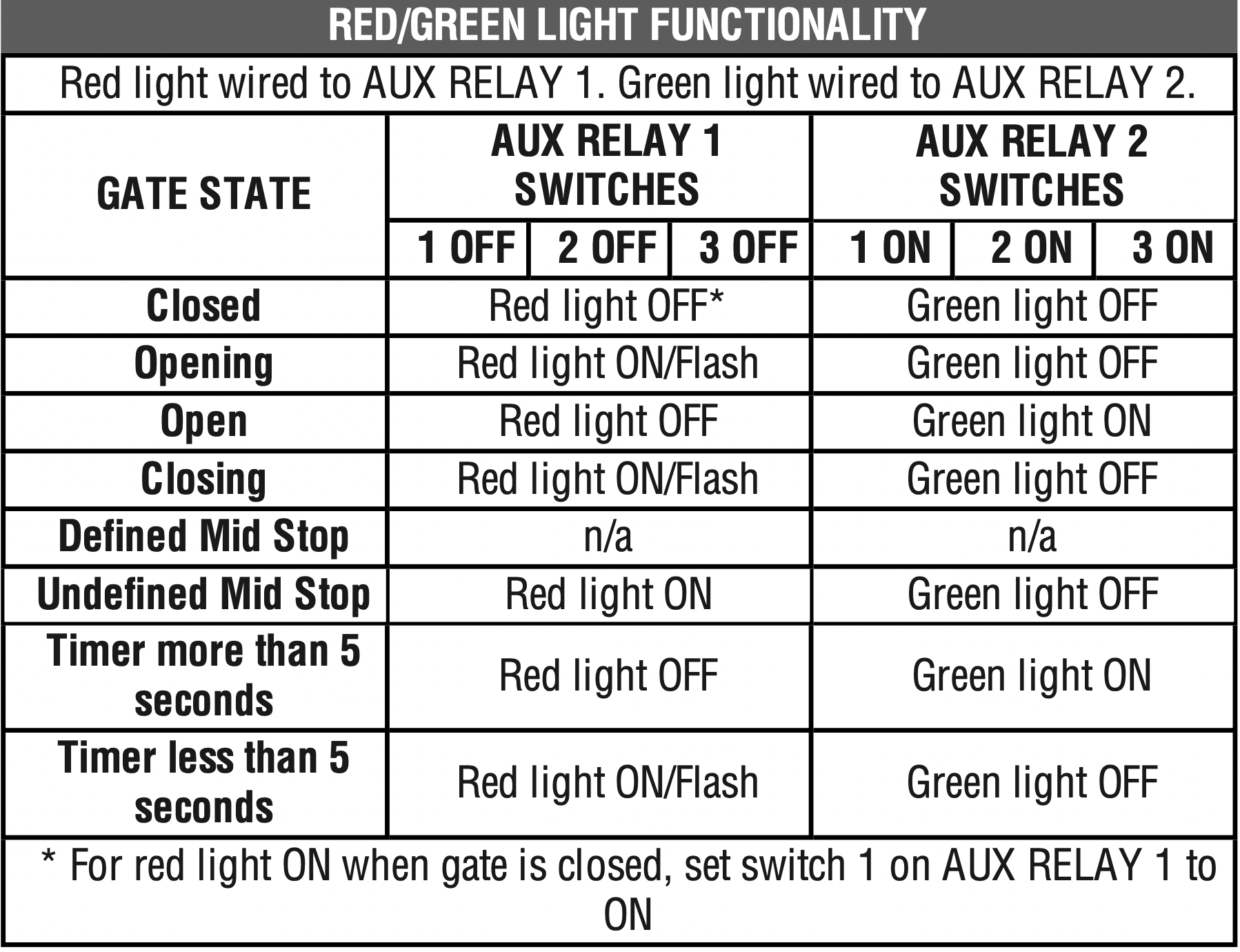
- AUX RELAY switches:
Set the AUX RELAY switches as needed to obtain the desired function as shown on the following page.
- EYE/EDGE switches:
Set the EYE/EDGE switches as needed to obtain the desired OPEN or CLOSE functionality.
- 1, 2, and 3 LEDs:
LEDs indicating the status of the EYE/EDGE inputs. Also used to check the firmware version of the expansion board:
1. Locate the 1, 2, and 3 LEDs on the expansion board.
2. Disconnect AC/DC power to the main control board for 15 seconds.
3. Connect power. The 1, 2, and 3 LEDs will flash in sequence until the main control board firmware revision is displayed. When the green POWER LED glows solid the LED 1 will flash the version number, then stop, then the LED 2 will flash the revision number (for example: For version 5.1 when the green POWER LED is solid the LED 1 will flash 5 times, then stop, then the LED 2 will flash once).
- MAIN BOARD input:
Input Connection for the main board connector.
- Input LEDs:
LEDs indicating the status of the SBC, OPN, CLS, and STP inputs.
- Loop detector inputs:
Inputs for the Plug-In Loop Detectors (Model LOOPDETLM)
- Wireless edge input:
Input for the Wireless Edge Kit (Model LMWEKITU)
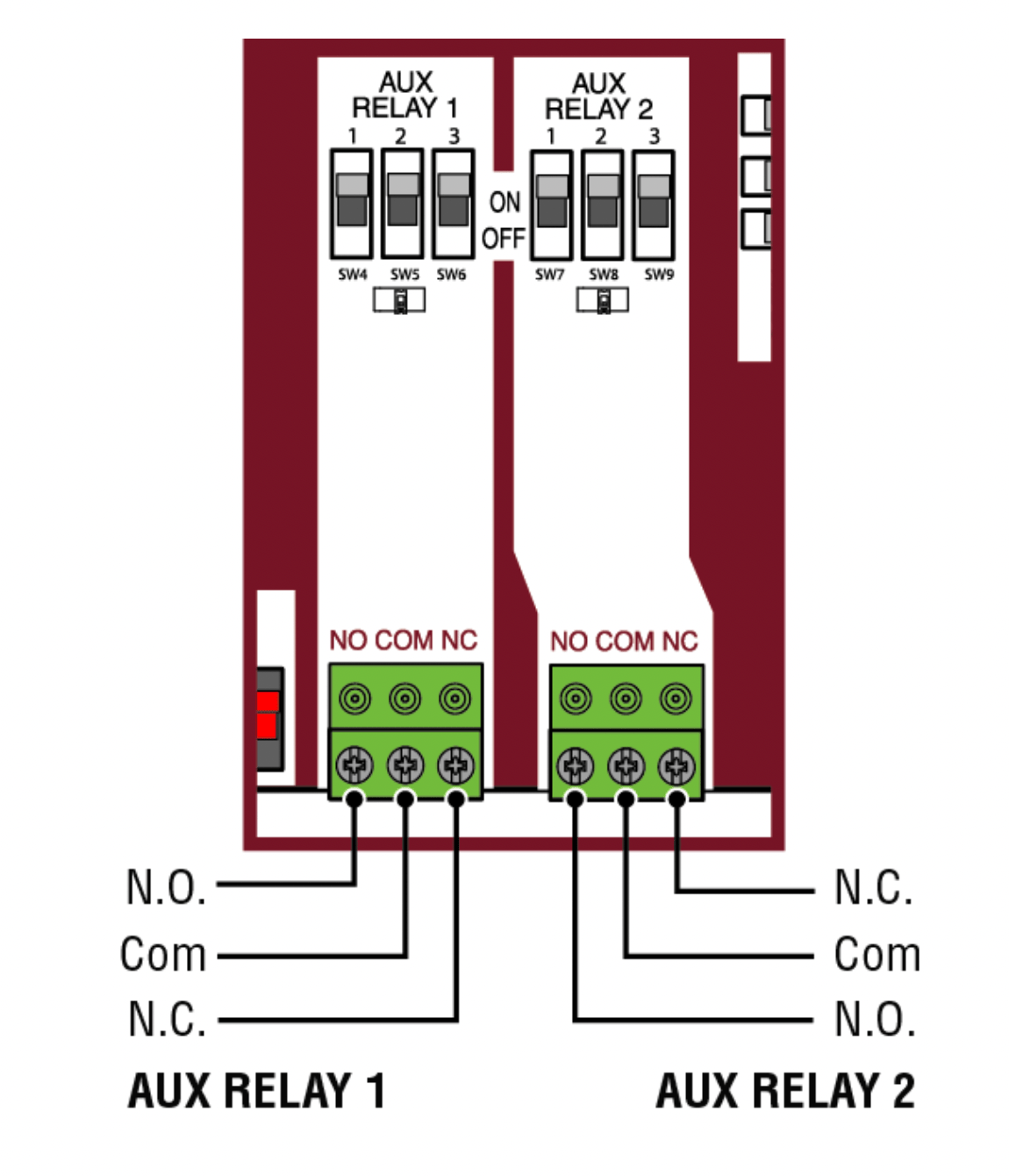
Auxiliary relay 1 and 2
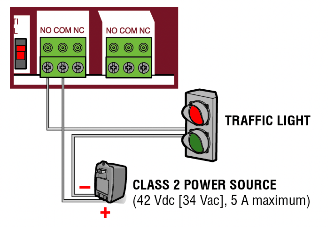
Normally Open (N.O.) and Normally Closed (N.C.) relay contacts to control external devices, for connection of Class 2, low voltage (42 Vdc [34 Vac] max 5 Amps) power sources only. Function of relay contact activation determined by switch settings.
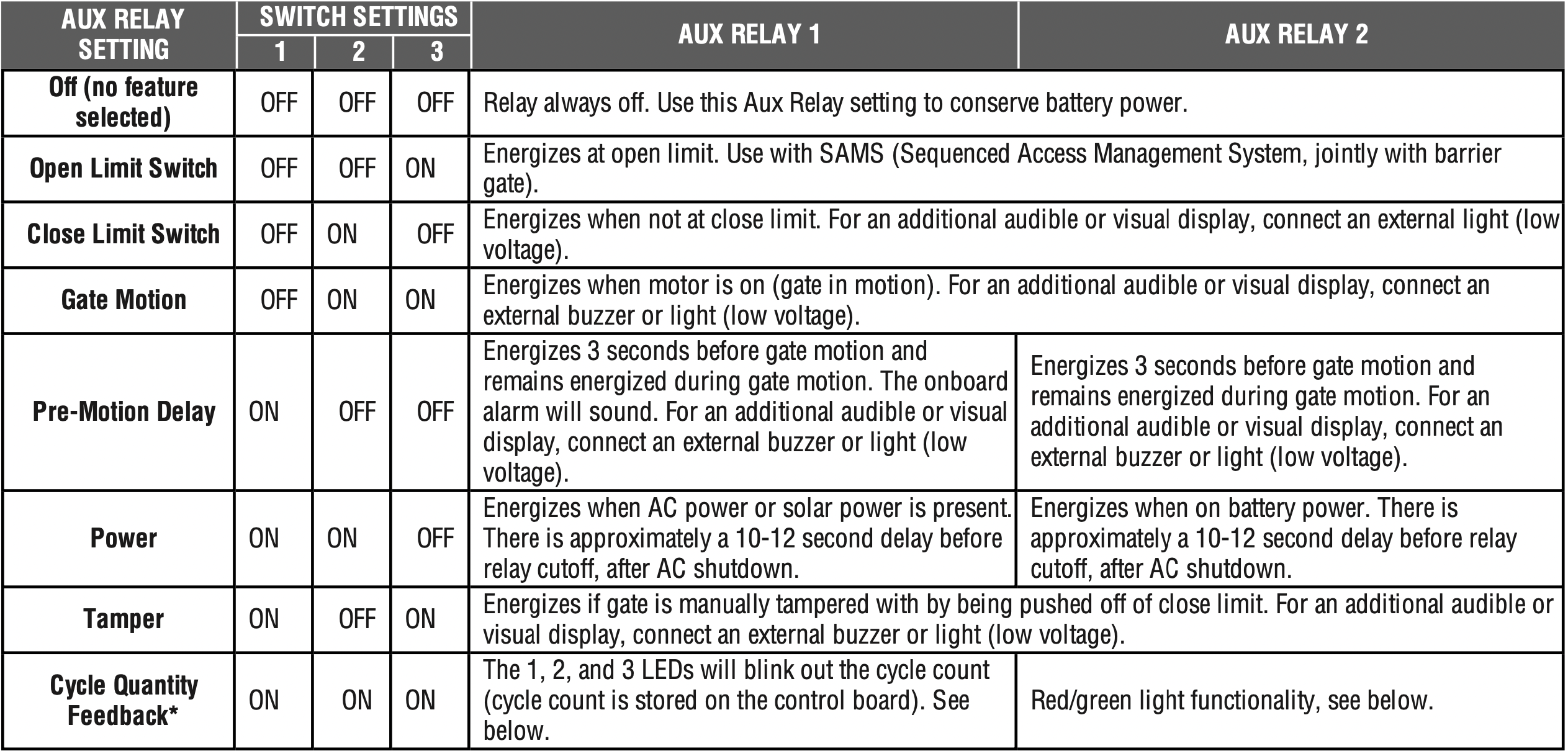
* Cycle count
First, note the current Aux Relay switch positions. To determine the actual cycles that the gate operator has run (in thousands), set all three Aux Relay switches to the ON setting for Aux Relay 1. The Expansion Board’s 1, 2, and 3 LEDs will blink out the cycle count, with 1 LED blinking 1000’s, 2 LED blinking 10,000’s, 3 LED blinking 100,000’s, and simultaneously all three LED’s blink 1,000,000’s (e.g. 1 LED blinks 3 times, 2 LED blinks 6 times, and 3 LED blinks once. Cycle count is 163,000.). Cycle count displayed is between 1,000 and 9,999,000 cycles. After servicing, set Aux Relay switches back to their appropriate positions. Cycle count cannot be reset or changed. If under 1,000 cycles the 1, 2, and 3 LEDs will turn on for 10 seconds, then turn off.
NOTE: The expansion board will flash the cycle count 3 times then all the LEDs will turn on solid for 10 seconds then turn off.
Auxiliary relay wiring example
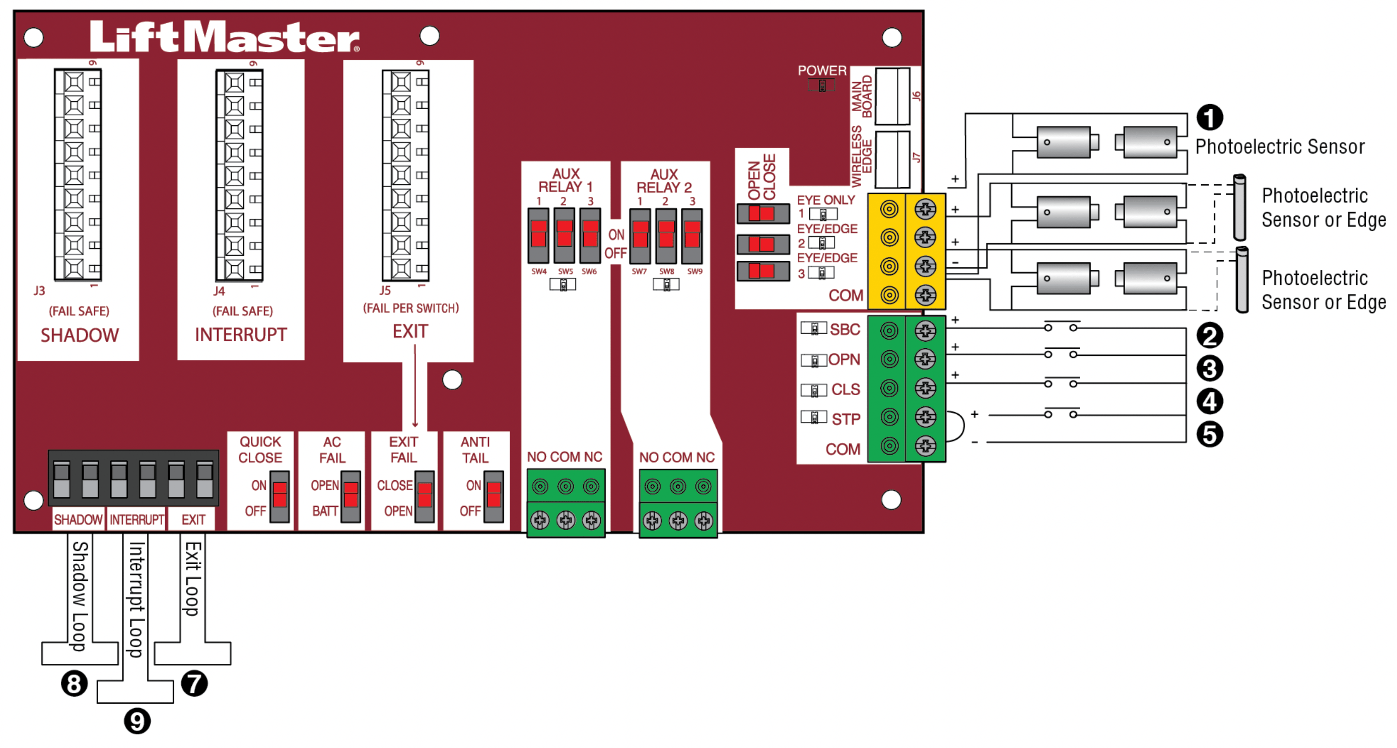
Wiring accessories to the expansion board
Refer to the chart below and the corresponding image for a description of the expansion board inputs.
|
1
|
Wireless edge
|
Connection for wireless edge receiver
|
|
2
|
Entrapment Protection Device Inputs (4 terminals total), Open or Close Direction based on switch setting next to inputs
|
EYES ONLY Input: Open or Close Direction Photoelectric Sensors, Close: reverses fully, Open: reverses 4 seconds
EYES/EDGE Input(s): Open or Close Direction Photo electric Sensors, Infrared detector wired or Edge Sensor, reverses 4 seconds
|
|
3
|
Single Button Control, SBC (2 terminals)
|
Gate command sequence - Open, Stop, Close, Stop, ... Soft Open, Soft Close, Soft Stop (maintained switch does not over ride external safeties and does not reset alarm condition)
|
|
4
|
Open Input (& common) (3-Button Control Station, 4 terminals total)
|
Open command - opens a closed gate.
Soft open (maintained switch does not over ride external safeties and does not reset alarm condition) If maintained, pauses Timer-to-Close at OPEN limit.
Opens a closing gate and holds open an open gate.
|
|
5
|
Close Input (& common) (3-Button Control Station, 4 terminals total)
|
Close command - closes an open gate.
Soft close (maintained switch does not over ride external safeties and does not reset alarm condition).
|
|
6
|
Stop Input (& common) (3-PB station, 4 terminals total)
|
Stop command - stops a moving gate.
Hard stop (maintained switch overrides Open and Close commands and resets alarm condition) If maintained, pauses Timer-to-Close at OPEN limit.
Overrides an Open or Close command.
|
|
7
|
Exit Loop Input (2 terminals)
|
Loop wire connection for plug-in loop detector when loop is inside secured area near gate.
Open command - opens a closed gate.
Soft open (maintained switch does not override external safeties and does not reset alarm condition) If maintained, pauses Timer-to-Close at OPEN limit.
Opens a closing gate and holds open an open gate.
|
|
8
|
Shadow Loop Input (2 terminals)
|
Loop wire connection for plug-in loop detector when loop is positioned under the gate.
- Holds open gateat open limit
- Disregarded during gate motion
- Pauses Timer-to-Close at Open Limit
|
|
9
|
Interrupt Loop Input (2 terminals)
|
Loop wire connection for plug-in loop detector when loop is along the side of the gate.
- Holds open gateat open limit
- Stops and reverses a closing gate
- Pauses Timer-to-Close at Open Limit
|
MAINTENANCE
IMPORTANT SAFETY INSTRUCTIONS
WARNING:
To reduce the risk of SEVERE INJURY or DEATH:
- READ AND FOLLOW ALL INSTRUCTIONS.
- ANY maintenance to the operator or in the area near the operator MUST NOT be performed until disconnecting the electrical power (AC or solar and battery) and locking-out the power via the operator power switch. Upon completion of maintenance the area MUST be cleared and secured, at that time the unit may be returned to service. Disconnect power at the fuse box BEFORE proceeding. Operator MUST be properly grounded and connected in accordance with national and local electrical codes. NOTE: The operator should be on a separate fused line of adequate capacity.
- NEVER let children operate or play with gate controls. Keep the remote control away from children.
- ALWAYS keep people and objects away from the gate. NO ONE SHOULD CROSS THE PATH OF THE MOVING GATE.
- The entrance is for vehicles ONLY. Pedestrians MUST use separate entrance.
- Test the gate operator monthly. The gate MUST reverse on contact with an object or reverse when an object activates the noncontact sensors. After adjusting the force or the limit of travel, retest the gate operator. Failure to adjust and retest the gate operator properly can increase the risk of INJURY or DEATH.
- Use the manual disconnect release ONLY when the gate is NOT moving.
- KEEP GATES PROPERLY MAINTAINED. Read the owner’s manual. Have a qualified service person make repairs to gate hardware.
- ALL maintenance MUST be performed by a LiftMaster professional. Activate gate ONLY when it can be seen clearly, is properly adjusted and there are no obstructions to gate travel.
- To reduce the risk of FIRE or INJURY to persons use ONLY LiftMaster part 29-NP712 for replacement batteries.
CAUTION: ALWAYS wear protective gloves and eye protection when changing the battery or working around the battery compartment.
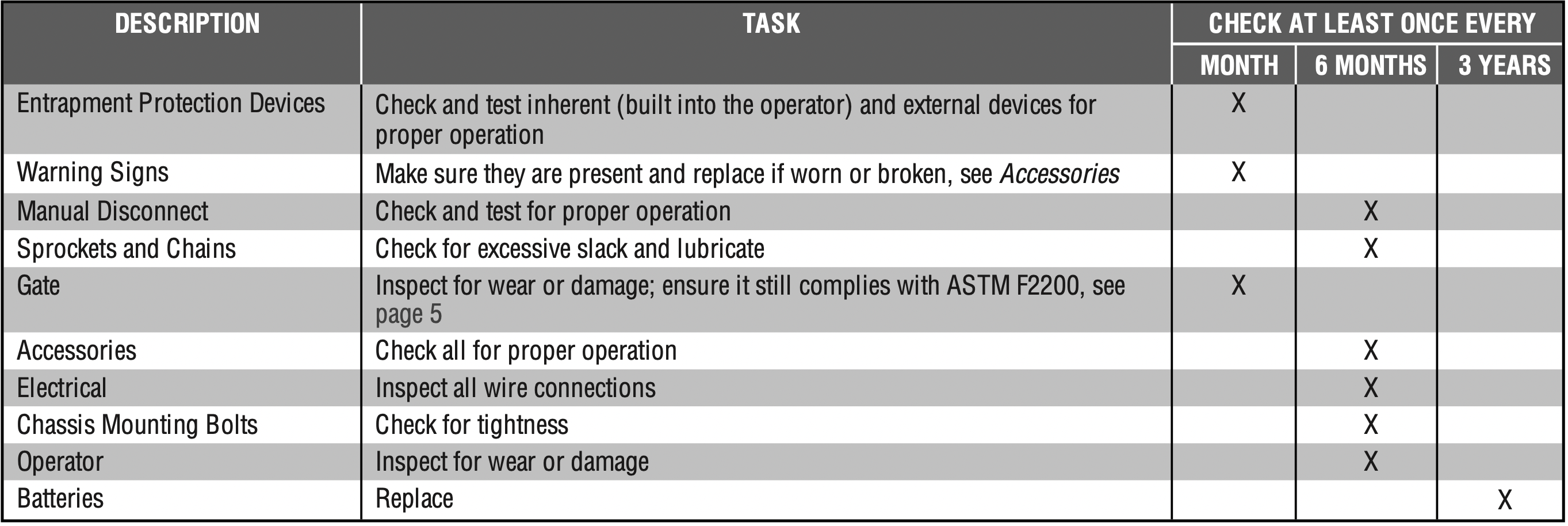
Maintenance Chart
Disconnect all power (AC, solar, battery) to the operator before servicing. The operator's AC Power switch ONLY turns off AC power to the control board and DOES NOT turn off battery power. ALWAYS disconnect the batteries to service the operator.
NOTES:
- Severe or high cycle usage will require more frequent maintenance checks.
- It is suggested that while at the site voltage readings be taken at the operator. Using a digital voltmeter, verify that the incoming voltage to the operator is within ten percent of the operator’s rating.
Batteries
Batteries will degrade over time depending on temperature and usage. The operator alarm will beep 3 times with a command if the battery is low. Batteries do not perform well in extremely cold temperatures. For best performance, the batteries should be replaced every 3 years. Use only LiftMaster part 29-NP712 for replacement batteries. The batteries contain lead and need to be disposed of properly.
The operator comes with two 7AH batteries. Two 33AH batteries (A12330SGLPK), Solar Harness Kit (K94-37236) with additional battery tray (K10-36183) may be used in place of the 7AH batteries.
NOTE: If your application includes a heater, two 33AH batteries will not fit into the operator enclosure.
TROUBLESHOOTING
WARNING:
To protect against fire and electrocution:
- DISCONNECT power (AC or solar and battery) BEFORE installing or servicing operator.
For continued protection against fire:
- Replace ONLY with fuse of same type and rating.
Diagnostic Codes
NOTE: When cycling or disconnecting power (ac/dc) to the control board, it is recommended that you unplug the J15 plug.
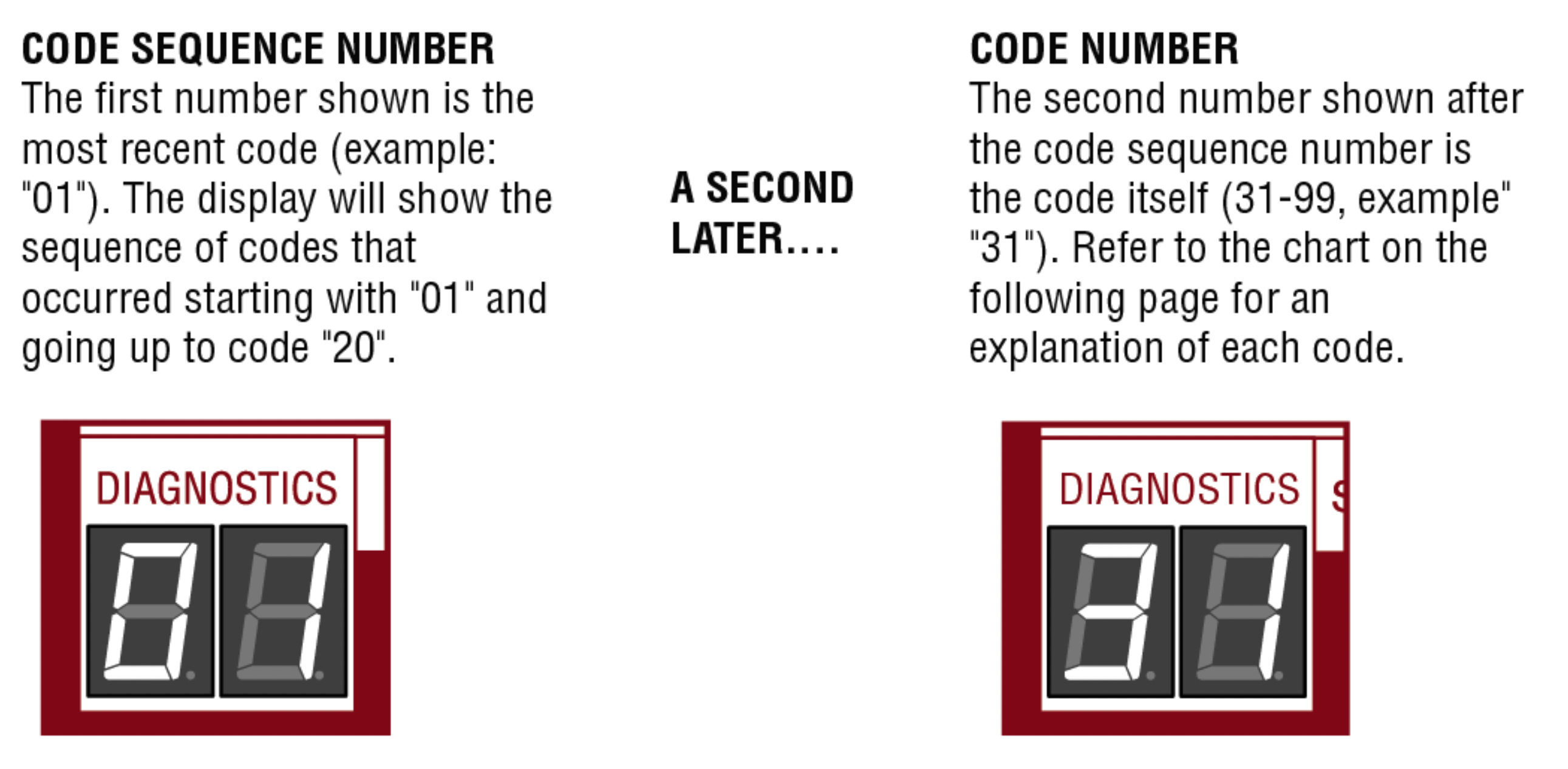
To View the Codes
The codes will show on the diagnostic display.
The operator will show the code sequence number followed by the code number:
To Scroll Through the Saved Codes
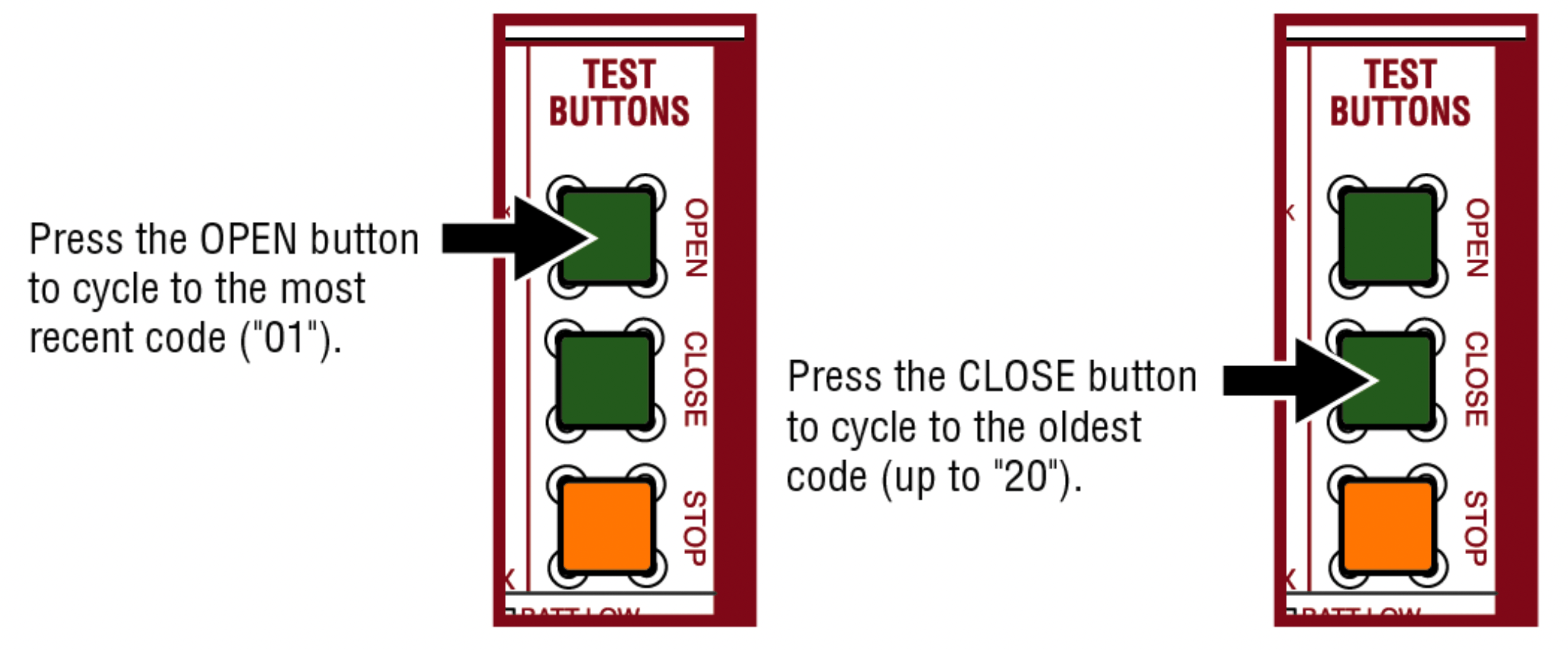
The operator will only keep track of up to 20 codes, then will start saving over the oldest codes as new codes occur.
To Exit
Press and release the STOP button to exit. The display will also time out after two minutes of inactivity.
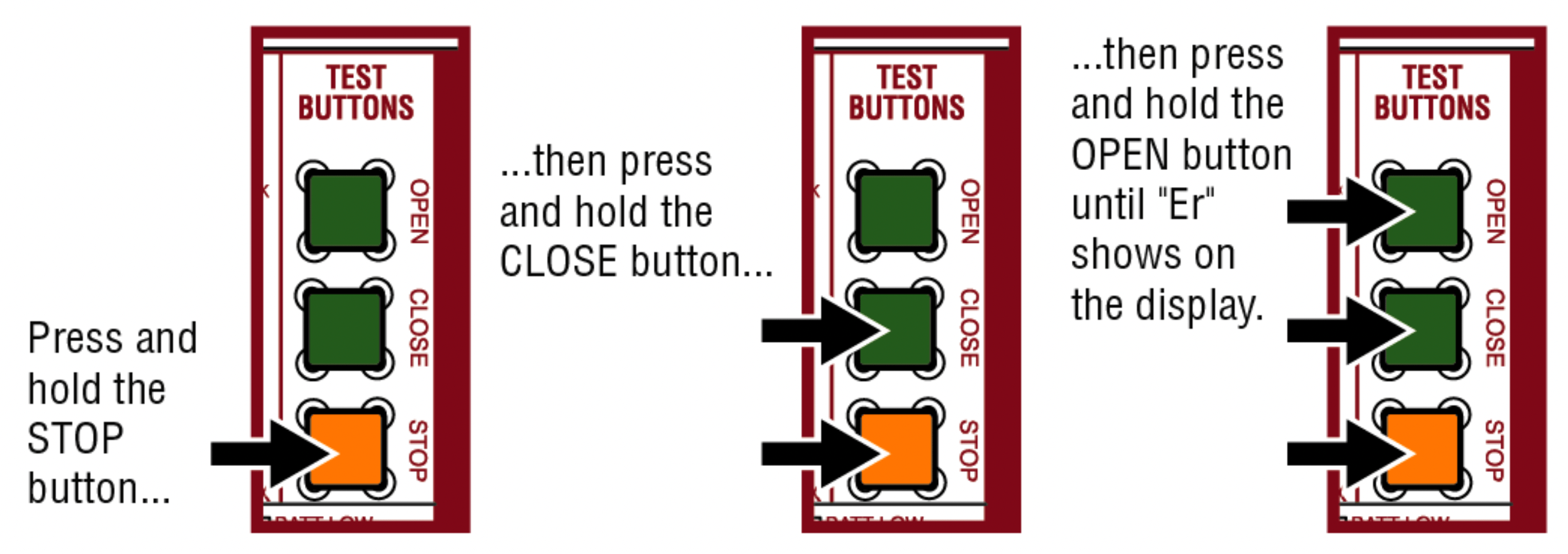
To Reset the Code History
- Press and hold the STOP button for six seconds. The display will show "Er" then "CL" alternately for six seconds.
- Release the STOP button. The code history has now been reset and the display will show "- -" until a new code occurs.
- Press and release the STOP button to exit.
Diagnostic Codes Table
Some codes are saved in the code history and some are not. If a code is not saved it will briefly appear on the display as it occurs, then disappear.
 LiftMaster System
 Installed System
 Informational
 External Entrapment Protection
 Inherent Entrapment Protection
| Code |
Meaning
|
Solution |
Saved |
|

|
Main control board has experienced aninternal failure.
|
Disconnect all power, wait 15 seconds, then reconnect power (reboot). If issue continues, replace main control board.
|
NO
|
 |
Absolute Position Encoder Error, not getting position information from encoder
|
Check APE assembly and wiring connections. Replace the APE assembly if necessary.
|
YES
|
|

|
Max-Run-Time Exceeded Error
|
Check for an obstruction, then reprogram the limits.
|
YES
|
|

|
Product ID Error
|
Was the control board just replaced? If so, erase limits, enter limit setup mode and set limits. If not, disconnect all power, wait 15 seconds, then reconnect power before changing product ID harness.
|
YES
|
|

|
Product ID Failure
|
Unplug product ID harness then plug back in. Disconnect all power, wait 15 seconds, then reconnect power before replacing product ID harness.
|
YES
|
|

|
Hard Stop Limit (Arm 1)
|
Limit may be set too tightly against a non-resilient hard stop (re-adjust limit). Operator may be at end of travel (re-adjust mounting).
|
NO
|
|

|
Battery over voltage
|
Too much voltage on the battery. Check harness. Make sure there is NOT a 24V battery on a 12V system.
|
YES
|
|

|
Battery over current
|
Possible short of the battery charge harness. Check harness. Make sure you do NOT have a 12V battery on a 24V system.
|
YES
|
|

|
No battery at boot up
|
Check battery connections and installation. Replace batteries if depleted to less than 20V on a 24V system or less than 10V on a 12V system. Make sure there is NOT a single 12V battery on a 24V system.
|
YES
|
|

|
Exit Loop Error
|
Failure or missing loop (SHORT or OPEN - LiftMaster Plug-in Loop Detector only) Check loop wiring throughout connection. May be a short in the loop, or an open connection in the loop.
|
YES
|
|

|
Shadow Loop Error
|
|

|
Interrupt Loop Error
|
|

|
Wireless edge battery low
|
Replace batteries in wireless edge.
|
YES
|
|

|
Run-Distance Error
|
The limits are less than the minimum requirement or longer than what was learned. Check limit positions and proper switch function. Run-distance can be re-learned by setting the handing again.
|
YES
|
|

|
Brown out occurred
|
AC/DC board supply dipped below allow able level. Review power supply and wiring. If rebooting, ensure enough time for discharge of power to force a fresh boot.
|
YES
|
|

|
Wireless Second Operator Communication Error
|
Check the second operator for power. If OFF, restore power and try to run the system. If powered, deactivate the wireless feature and then re-learn the second operator.
|
YES
|
|

|
Minimum number of monitored entrapment protection devices not installed.
|
Review monitored entrapment protection device connections. This swing gate operator will operate only after installation of a minimum of one external safety device in either the open or close direction.
|
NO
|
|

|
CLOSE EYE/INTERRUPT held more than 3 minutes
|
Check wired input on main control board; check for alignment or obstruction.
|
YES
|
|

|
CLOSE EDGE held more than 3 minutes
|
|

|
OPEN EYE/EDGE held more than 3minutes
|
|

|
CLOSE EYE/INTERRUPT held more than 3 minutes
|
Check wired input on expansion board; check for alignment or obstruction.
|
YES
|
|

|
CLOSE EYE/EDGE held more than 3minutes
|
|

|
OPEN EYE/EDGE held more than 3minutes
|
|

|
Wireless edge triggered more than 3minutes
|
Check wired input for wiring issue or obstruction.
|
YES
|
|

|
Wireless edge loss of monitoring
|
Check wireless edge inputs.
|
YES
|
|

|
Wireless edge triggered
|
IF an obstruction occurred, no action required. If an obstruction did NOT occur, check inputs and wiring.
|
NO
|
|

|
CLOSE EYE/INTERRUPT triggered, causing reversal, preventing close, or resetting TTC
|
IF an obstruction occurred, no action required. If an obstruction did NOT occur, check alignment, inputs, and wiring on main control board
|
NO
|
|

|
CLOSE EDGE triggered, causing reversal, NO preventing close, or canceling TTC
|
|

|
OPEN EYE/EDGE triggered, causing reversal or preventing opening
|
|

|
CLOSE EYE/INTERRUPT triggered, causing reversal, preventing close, or resetting TTC
|
IF an obstruction occurred, no action required. If an obstruction did NOT occur, check alignment, inputs, and wiring on expansion board.
|
NO
|
|

|
CLOSE EYE/EDGE triggered, causing reversal and preventing close or canceling TTC
|
|

|
OPEN EYE/EDGE triggered, causing reversal or preventing opening
|
|

|
Close input (EYE/EDGE) communication faultfrom other operator
|
Check inputs and communication method between operators, either wired bus or radio. Ensure operator is powered. May have to erase the wireless communication and reprogram the two operators.
|
YES
|
|

|
Open input (EYE/EDGE) communication fault from other operator
|
|

|
Close input (EYE/EDGE) communication fault (expansion board)
|
Check the connections between the main board and the expansion board.
|
YES
|
|

|
Open input (EYE/EDGE) communication fault (expansion board)
|
|

|
Non-monitored device detected on the wireless safety system
|
Non-monitored contact closure devices are not supported. Make sure connected devices are monitored. Check edges for proper orientation and resistive end cap connection.
|
YES
|
|

|
Force Reversal (Operator 1)
|
Check for obstruction. If no obstruction, check that the mechanical assembly is engaged and free to move. See section on Limit and Force Adjustment, and Obstruction Test.
|
YES
|
|

|
RPM / STALL Reversal (Operator 1)
|
Check for obstruction. If no obstruction, check the operator wiring and that the mechanical assembly is engaged and free to move. Replace APE assembly.
|
YES
|
|
99
|
Normal Operation
|
No action required
|
YES
|
Control Board LEDs
| STATUS LEDS |
|
INPUT POWER
|
OFF
|
OFF state
|
|
ON
|
AC charger or Solar power available
|
|
BATT CHARGING
|
OFF
|
Not charging
|
|
ON
|
Three stage battery charging
|
|
TIMER
|
OFF
|
The timer is disabled
|
|
ON
|
The timer is enabled
|
|
MEDIUM BLINK (1 blink per second)
|
The timer is running
|
|
FAST BLINK (2 blinks per second)
|
The timer is paused
|
|
FASTEST BLINK (8 blinks per second)
|
The timer is canceled
|
|
GATE MOVING
|
OFF
|
The gate is stopped
|
|
ON
|
The gate is opening or closing
|
|
MEDIUM BLINK (1 blink per second)
|
Operator is in E1 (single entrapment)
|
|
FASTEST BLINK (8 blinks per second)
|
The operator is in E2 (double entrapment)
|
|
BATT LOW
|
OFF
|
No battery error
|
|
ON
|
Battery low
|
|
MEDIUM BLINK (1 blink per second)
|
Battery critically low
|
|
ACC PWR OVLD
|
OFF
|
Accessory power is okay
|
|
ON
|
Accessory overload protector opened
|
| INPUT LEDS |
|
OPEN, CLOSE, STOP INPUT
|
OFF
|
Input inactive
|
|
ON
|
Input active
|
|
BLINK
|
Input active on other operator
|
|
FIRE DEPT INPUT
|
OFF
|
Input inactive
|
|
ON
|
Input active
|
|
BLINK
|
Input active on other operator
|
|
EXIT
|
OFF
|
Input inactive
|
|
ON
|
Input active
|
|
BLINK
|
Input active on other operator
|
|
SHADOW
|
OFF
|
Input inactive
|
|
ON
|
Input active
|
|
BLINK
|
Input active on other operator
|
|
CLOSE EYES/INTERRUPT
|
OFF
|
Input inactive
|
|
ON
|
Input active
|
|
BLINK
|
Input active on other operator
|
|
CLOSE EDGE
|
OFF
|
Input inactive
|
|
ON
|
Input active
|
|
BLINK
|
Input active on other operator
|
|
OPEN EYES/EDGE
|
OFF
|
Input inactive
|
|
ON
|
Input active
|
|
BLINK
|
Input active on other operator
|
|
LOCK
|
OFF
|
Maglock relay inactive
|
|
ON
|
Maglock relay active
|
Troubleshooting Chart
| SYMPTOM |
POSSIBLE CAUSES |
SOLUTIONS |
|
Operator does not run and diagnostic display not on.
|
- No power to controlboard
- Open fuse
- If on battery power only, low or dead batteries
- Defective control board
|
- Check AC and battery power
- Check fuses
- Charge batteries by AC or solar power or replace batteries
- Replace defective control board
|
|
Control board powers up, but motor does not run.
|
- Reset switch is stuck
- Stop button active or jumper not in place for stop circuit
- If on battery power only, low or dead batteries
- Open or Close input active
- Entrapment Protection Device active
- Vehicle loop detector or probe active
- Defective control board
|
- Check reset switch
- Check Stop button is not “stuck on”, or verify that the stop button is a normally closed circuit, or put a jumper on the stop circuit.
- Charges batteries by AC or solar power or replace batteries
- Check all Open and Close inputs for a “stuck on” input
- Check all Entrapment Protection Device inputs for a “stuck on” sensor
- Check all vehicle detector inputs for a “stuck on” detector
- Replace defective control board
|
|
Gate moves, but can not set correct limits.
|
- Gate does not move to a limit position
- Gate is too difficult to move
|
- Use manual disconnect, manually move gate, and ensure gate moves easily limit to limit.
Repair gate as needed.
- Gate must move easily and freely through its entire range, limit to limit.
Repair gate as needed.
|
|
Gate does not fully open or fully close when setting limits.
|
- Gate does not move to a limit position
- Gate is too difficult to move
|
- Use manual disconnect, manually move gate, and ensure gate moves easily limit to limit. Repair gate as needed.
- Gate must move easily and freely through its entire range, limit to limit.
Repair gate as needed.
|
|
Operator does not respond to a wired control/command (example: Open, Close, SBC, etc.)
|
- Check Open and Close command input LEDs
- Stop button is active
- Reset button is stuck
- If on battery power only, low or dead batteries
- Entrapment Protection Device active
- Vehicle loop detector or vehicle probe active
|
- Check all Open and Close inputs for a “stuck on” input
- Check Stop button is not “stuck on”
- Check Reset button
- Charges batteries by AC or solar power or replace batteries
- Check all Entrapment Protection Device inputs for a “stuck on” sensor
- Check all vehicle detector inputs for a “stuck on” detector
|
|
Operator does not respond to a wireless control or transmitter
|
- Check XMITTER LED when wireless control is active
- Stop button is active
- Reset button is stuck
- Poor radio reception
|
- Activate wireless control and check XMITTER LED is on. Re-learn wireless control/transmitter to control board. Replace wireless control as needed.
- Check Stop button is not “stuck on”
- Check Reset button
- Check if similar wired control operates correctly. Check if wireless controls works properly when within a few feet of operator. Check operator’s antenna and antenna wire. Check other wireless controls or devices.
|
|
Gate stops during travel and reverses immediately.
|
- Control (Open, Close) becoming active
- Vehicle loop detectoractive
- Low battery voltage
|
- Check all Open and Close inputs for an active input
- Check all vehicle detector inputs for an active detector
- Battery voltage must be 23.0 Vdc or higher. Charge batteries by AC or solar power or replace batteries
|
|
Gate opens, but will not close with transmitter or Timer-to-Close.
|
- Open control active
- Vehicle loop detector active
- Loss of AC power with AC FAIL set to OPEN
- Low battery with LOW BATT set to OPEN
- Fire Dept input active
- Timer-to-Close not set
- Close Entrapment Protection Device active
|
- Check all Open inputs for an active input
- Check all vehicle detector inputs for an active detector
- Check AC power and AC Fail option setting
- Check if AC power is available. If no AC power, then running on batteries and battery voltage must be 23.0 Vdc or higher. Charge batteries by AC or solar power or replace batteries.
- Check Fire Dept input
- Check Timer-to-Close (TTC) setting
- Check all Entrapment Protection Device inputs for an active sensor
|
|
Gate closes, but will not open.
|
- Vehicle loop detector active
- Low battery with LOW BATT option set to CLOSE
|
- Check all vehicle detector inputs for an active detector
- Check if AC power is available. If no AC power, then running on batteries and battery voltage must be 23.0 Vdc or higher. Charge batteries by AC or solar power or replace batteries.
|
|
Exit loop activation does not cause gate to open.
|
- Exit vehicle detector setup incorrectly
- Defective Exit loop detector
- Low battery with LOW BATT option set to CLOSE
|
- Review Exit loop detector settings. Adjust settings as needed.
- Replace defective Exit loop detector.
- Check if AC power is available. If no AC power, then running on batteries and battery voltage must be 23.0 Vdc or higher. Charge batteries by AC or solar power or replace batteries.
|
|
Interrupt loop does not cause gate to stop and reverse.
|
- Vehicle detector set up incorrectly
- Defective vehicle loop detector
- Anti-tail set to ON
|
- Review Interrupt loop detector settings. Adjust settings as needed.
- Replace defective Interrupt loop detector.
- Set anti-tail to OFF.
|
|
Shadow loop does not keep gate at open limit.
|
- Vehicle detector set up incorrectly
- Defective vehicle loop detector
|
- Review Shadow loop detector settings. Adjust settings as needed.
- Replace defective Shadow loop detector.
|
|
Obstruction in gate's path does not cause gate to stop and reverse.
|
|
- Refer to the Adjustment section to conduct the obstruction test and perform the proper force adjustment that is needed.
|
|
Photo electric sensor does not stop or reverse gate.
|
- Incorrect photo electric sensor wiring
- Defective photo electric sensor
|
- a. Check photoelectric sensor wiring. Retest that obstructing photoelectric sensor causes moving gate to stop,and may reverse direction.
- b. Replace defective photoelectric sensor. Retest that obstructing photoelectric sensor causes moving gate tostop, and may reverse direction.
|
|
Edge Sensor does not stop or reverse gate.
|
- Incorrect edge sensor wiring
- Defective edge sensor
|
- Check edge sensor wiring. Retest that activating edge sensor causes moving gate to stop and reverse direction.
- Replace defective edge sensor. Retest that activating edge sensor causes moving gate to stop and reverse direction.
|
|
Alarm sounds for 5 minutes or alarm sounds with a command.
|
- Double entrapment occurred (two obstructions within a single activation)
|
- Check for cause of entrapment (obstruction) detection and correct. Press the reset button to shut off alarm and reset the operator.
|
|
Alarm beeps three times with a command.
|
|
- Check if AC power is available. If no AC power, then running on batteries and battery voltage must be 23.0 Vdc or higher. Charge batteries by AC or solar power or replace batteries
|
|
On dual-gate system, incorrect gate opens first or closes first.
|
- Incorrect Bipart switch setting
|
- Change setting of both operator’s Bipart switch settings. One operator should have Bipart switch ON (operator that opens second) and the other operator should have Bi part switch OFF (operator that opens first).
|
|
Alarm beeps when running.
|
- Expansion board setting
- Constant pressure to open or close is given
|
- Pre-warning is set to "ON"
- Constant pressure to open or closed is given
|
|
Expansion board function not controlling gate.
|
- Defective main board to expansion board wiring
- Incorrect input wiring to expansion board
- Defective expansion board or defective main board
|
- Check main board to expansion board wiring. If required, replace wire cable.
- Check wiring to all inputs on expansion board.
- Replace defective expansion board or defective main board
|
|
Maglock not working correctly.
|
- Maglock wired incorrectly
|
- Check that Maglock is wired to N.C. and COM terminals. Check that Maglock has power (do not power maglock from control board accessory power terminals). If shorting lock’s NO and COM wires does not activate Maglock, then replace Maglock or Maglock wiring (refer to Wiring Diagrams).
|
|
Solenoid lock not working correctly.
|
- Solenoid wired incorrectly
|
- Check that Solenoid is wired to N.O. and COM terminals. Check that Solenoid has power (do not power solenoid from control board accessory power terminals). If shorting lock’s NC and COM wires does not activate Solenoid, then replace Solenoid lock or Solenoid wiring (refer to Wiring Diagrams).
|
|
Switched (SW) Accessory power remaining on.
|
|
|
|
Accessories connected to Switch (SW) Accessory power not working correctly, turning off, or resetting.
|
|
- Move accessory to accessory power "ON"
|
|
Accessories connected to Accessory power not working correctly, turning off, or resetting.
|
- Accessory power protector active
- Defective control board
|
- Disconnect all accessory powered devices and measure accessory power voltage (should be 23 – 30 Vdc). If voltage is correct, connect accessories one at a time, measuring accessory voltage after every new connection.
- Replace defective control board
|
|
Quick Close not working correctly.
|
- Quick Close setting incorrect
- Interruptloop detector
- DefectiveExpansionboard
|
- Check that Quick Close setting is ON
- Check operation of Interrupt Loop detector
- Replace defective Expansion board
|
|
Anti-Tail gating not working correctly.
|
- Anti-Tail setting incorrect
- Interrupt loop detector
- Defective Expansion board
|
- Check that Anti-Tail setting is ON
- Check operation of Interrupt Loop detector
- Replace defective Expansion board
|
|
AUX Relay not working correctly.
|
- AUX Relay setting incorrect
- AUX Relay wiring incorrect
- DefectiveExpansionboard
|
- Check AUX Relay switches settings
- Check that wiring is connected to either N.O. and COM or to N.C. and COM.
- Set AUX Relay to another setting and test. Replace defective expansion board.
|
|
Solar operator not getting enough cycles per day.
|
- Insufficient panel wattage
- Excessive accessory power draw
- Old batteries
- Solar panels are not getting enough sunlight
|
- Add more solar panels
- Reduce the accessory power draw by using LiftMaster low power accessories
- Replace batteries
- Relocate the solar panels away from obstructions (trees, buildings, etc.)
|
|
Solar operator, insufficient stand by time.
|
- Insufficientpanel wattage
- Excessive accessory power draw
- Battery capacity too low
|
- Add more solar panels
- Reduce the accessory power draw by using LiftMaster low power accessories
- Use batteries with higher amp hour (AH) rating
|