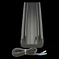
WRAPAROUND EDGE
Models WR4, WR5, WR6, WS4, WS5, WS6
LiftMaster
®
sensing edges provide monitored
entrapment protection. Sensing edges are UL
Recognized Components and meet UL 325
requirements. A monitored entrapment protection
device MUST be installed in each entrapment zone.
For use with LiftMaster
®
door and gate operators
and wireless edge kit. Refer to the operator manual
to ensure compatibility.
NOT FOR USE ON SWING GATES.
Model WR4 4 Foot Wraparound Round Edge
Model WR5 5 Foot Wraparound Round Edge
Model WR6 6 Foot Wraparound Round Edge
Model WS4 4 Foot Wraparound Square Edge
Model WS5 5 Foot Wraparound Square Edge
Model WS6 6 Foot Wraparound Square Edge
OVERVIEW
Illustrations are for reference only, your application
may look different.
To prevent possible SERIOUS INJURY or DEATH from a closing gate or door:
• Be sure to DISCONNECT ALL POWER to the operator BEFORE installing the sensing edge.
• The gate or door MUST be in the fully opened or closed position BEFORE installing the LiftMaster
®
Monitored Entrapment Protection device.
• Correctly install, connect, and test the sensing edge for proper operation.
• LiftMaster
®
Monitored Entrapment Protection devices are for use with LiftMaster
®
UL 325 compliant Gate and Commercial Door Operators and accessories ONLY. Use
with ANY other product voids the warranty.
• Monitored external entrapment protection devices MUST be installed per the operator installation manual for each Entrapment Zone.
• NOT for use on swing gates.
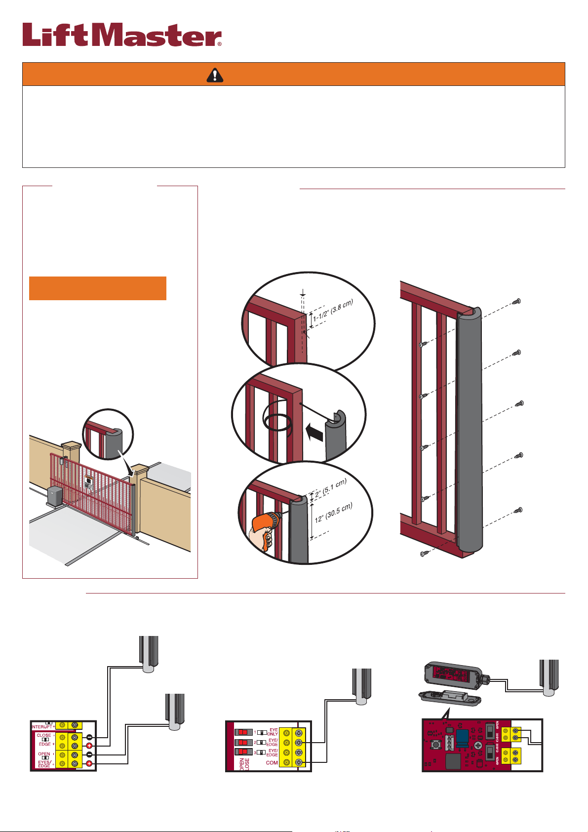
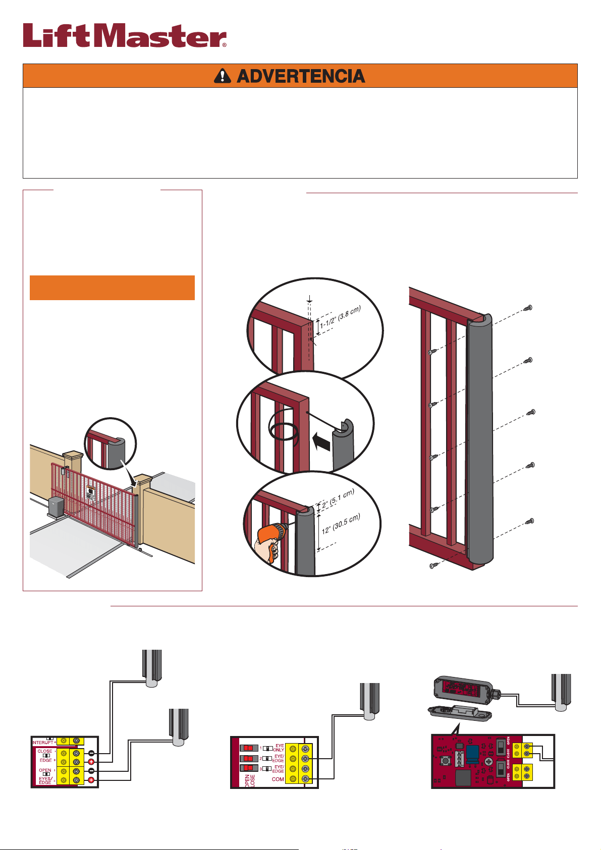
For close cycle
Control Board
For open cycle
Expansion Board
For open or
close cycle
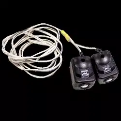
Wireless edge transmitter
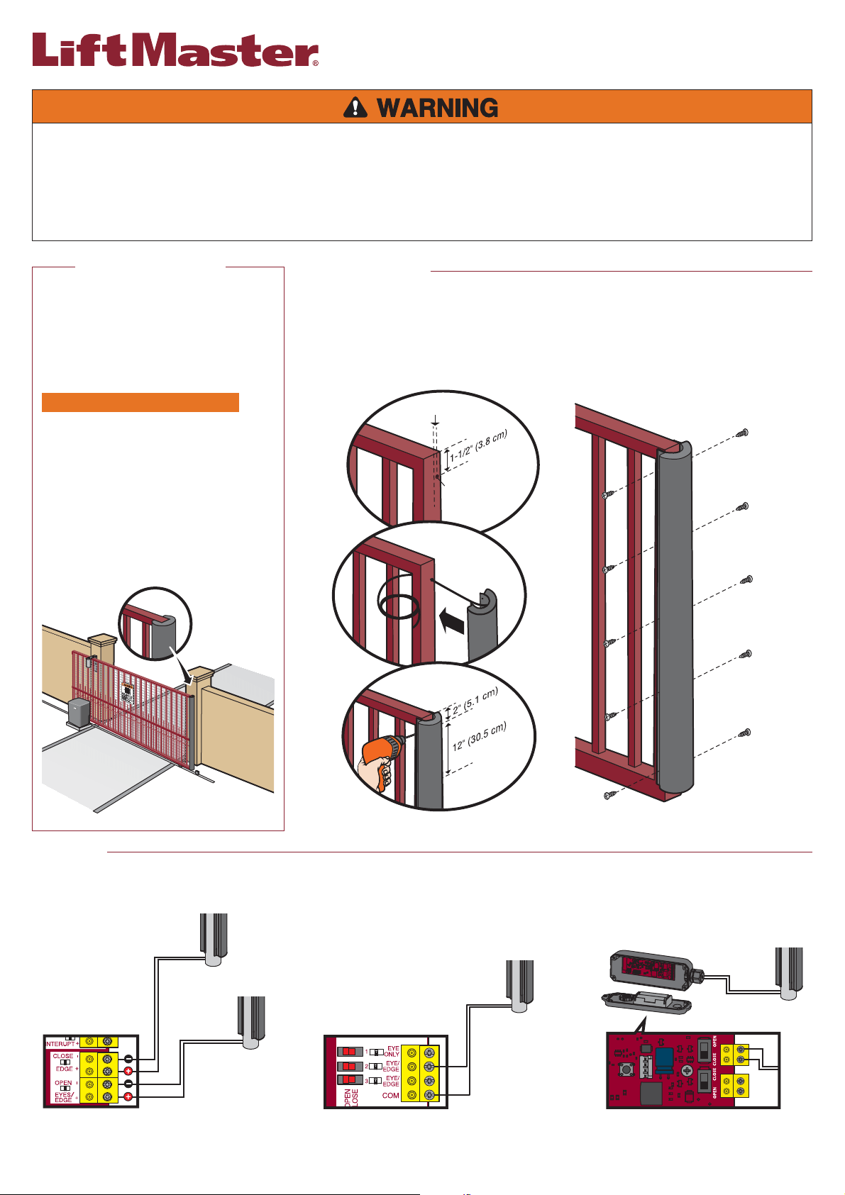
INTRODUCTION INSTALLATION
1. Measure 1-1/2" (3.8 cm) from the top edge of the gate and 0.8" (2 cm) off center of the gate as shown. Drill a
1/2" (1.3 cm) hole in this location.
2. Insert the wire from the wraparound edge through the hole and fit the edge around the gate frame.
3. Measure 2" (5.1 cm) from the top of the edge and pre-drill a 1/8" (0.3 cm) hole through the mounting flange
and gate. Continue to pre-drill holes every 12" (30.5 cm) for the length of the gate.
4. Secure the edge to the gate with self-tapping screws (not provided).
1. Connect the wires to the EDGE terminal on the operator control board, the EYE/EDGE terminal on the expansion board, or to the LiftMaster LMWEKITU wireless edge transmitter. A
wireless edge transmitter is recommended (not provided). Place an obstruction at different points of gate travel. 2. Reconnect power and operate gate. The gate will stop and reverse.
3. Test ALL installed edge sensors for proper operation.
0.8" (2 cm)
1/2"
(1.3 cm)
WIRING
BORDURE ENVELOPPANTE
Modèles WR4, WR5, WR6, WS4, WS5, WS6
Les bordures détectrices LiftMaster
®
fournissent une
protection surveillée contre le piégeage. Les bordures
détectrices sont des composants homologués par l’UL et
qui répondent aux exigences de la norme UL 325. Un
dispositif surveillé de protection contre le piégeage DOIT
être installé dans chaque zone de piégeage. Pour usage
avec les actionneurs de porte et de barrière et le
nécessaire de bordure sans fil LiftMaster
®
. Consulter le
manuel de l’actionneur pour garantir la compatibilité du
produit.
USAGE NON PRÉVU SUR DES
BARRIÈRES PIVOTANTES.
Modèle WR4 Bordure enveloppante de 1,2 m (4 pi)
Modèle WR5 Bordure enveloppante de 1,5 m (5 pi)
Modèle WR6 Bordure enveloppante de 1,8 m (6 pi)
Modèle WS4 Bordure enveloppante carrée de 1,2 m (4 pi)
Modèle WS5
Bordure enveloppante carrée de 1,5 m (5 pi)
Modèle WS6
Bordure enveloppante carrée de 1,8 m (6 pi)
VUE D’ENSEMBLE
Les illustrations ne sont fournies qu’à titre de référence,
votre application pourrait avoir une apparence différente.
Pour prévenir d’éventuelles BLESSURES GRAVES, voire MORTELLES lorsqu’une porte ou une barrière se ferme :
• S’assurer de DÉBRANCHER L’ALIMENTATION à l’actionneur AVANT d’installer la bordure détectrice.
• La barrière DOIT être complètement ouverte ou complètement fermée AVANT d’installer le dispositif surveillé de protection contre le piégeage LiftMaster
®
.
• Installer et connecter correctement la bordure détectrice et en vérifier le bon fonctionnement par une mise à l’essai.
• Les dispositifs surveillés de protection contre le piégeage LiftMaster
®
sont prévus pour être utilisés UNIQUEMENT avec les actionneurs de barrière et de porte
commerciale LiftMaster
®
conformes à la norme UL 325. L’utilisation avec TOUT autre produit annule la garantie.
• Les dispositifs de protection contre le piégeage DOIVENT être installés selon les instructions fournies dans le manuel du propriétaire pour chaque zone de piégeage.
• NON prévu pour un usage sur des barrières pivotantes.
Tableau de commande
Pour le cycle
de fermeture
Pour le cycle
d’ouverture
Tableau d’extension
Pour le cycle
d’ouverture
ou de fermeture
Émetteur sans fil de bordure
ATTENTION
AVERTISSEMENT
AVERTISSEMENT
AVERTISSEMENT
AVERTISSEMENT
INTRODUCTION INSTALLATION
1. Mesurer 3,8 cm (1,5 po) du bord supérieur de la barrière et 2 cm (0,8 po) du centre de la barrière comme montré. Percer un
trou de 1,3 cm (1/2 po) à cet endroit.
2. Insérer le fil de la bordure enveloppante par le trou et ajuster la bordure autour du cadre de la barrière.
3. Mesurer 5,1 cm (2 po) du haut de la bordure et prépercer un trou de 0,3 cm (1/8 po) à travers la bride de montage et la
barrière. Continuer de prépercer des trous tous les 30,5 cm (12 po) sur toute la longueur de la barrière.
4. Fixer la bordure à la barrière avec les vis autotaraudeuses.
1. Connecter les fils à la borne EDGE (bordure) sur le tableau de commande de l’actionneur, à la borne EYE/EDGE (cellule photoélectrique/bordure) du tableau d’extension ou à l’émetteur sans fil de la bordure
LiftMaster LMWEKITU. Un émetteur sans fil de bordure est recommandé (non fourni). Placer un obstacle à différents points de la trajectoire de la barrière. 2. Reconnecter l’alimentation et faire fonctionner la
barrière. La barrière s’arrêtera et inversera sa course. 3. Tester TOUS les capteurs pour vérifier leur bon fonctionnement.
0.8" (2 cm)
1/2"
(1.3 cm)
CÂBLAGE
BORDE DE LA ENVOLTURA
Modelos WR4, WR5, WR6, WS4, WS5, WS6
Los bordes de detección de LiftMaster
®
proporcionan
protección contra atrapamientos monitoreada. Los bordes
de detección son componentes reconocidos por UL y
cumplen con los requerimientos de UL 325. Se DEBE
instalar un dispositivo de protección contra atrapamientos
monitoreado en cada zona de atrapamiento. Para usar con
operadores de puertas y compuertas LiftMaster
®
y el
juego de borde inalámbrico. Consulte el manual del
operador para garantizar la compatibilidad.
NO APTO PARA USO EN COMPUERTAS
ABATIBLES.
Modelo WR4 Borde redondo de envoltura de 4 pies (1.2m)
Modelo WR5 Borde redondo de envoltura de 5 pies (1.5m)
Modelo WR6
Borde redondo de envoltura de 6 pies (1.8m)
Modelo WS4
Borde cuadrado de envoltura de 4 pies (1.2m)
Modelo WS5
Borde cuadrado de envoltura de 5 pies (1.5m)
Modelo WS6 Borde cuadrado de envoltura de 6 pies (1.8m)
DESCRIPCIÓN GENERAL
Las ilustraciones son solo de referencia, su solicitud
puede tener un aspecto diferente.
Para evitar la posibilidad de una LESIÓN GRAVE O INCLUSO LA MUERTE cuando una puerta o compuerta se esté cerrando:
• Asegúrese de DESCONECTAR TODA LA ENERGÍA al operador ANTES de instalar el borde de detección.
• La compuerta o puerta DEBEN estar en una posición totalmente abierta o cerrada ANTES de instalar el dispositivo de protección contra atrapamientos monitoreado LiftMaster
®
.
• Instale, conecte y pruebe correctamente el borde de detección para una operación correcta.
• Los dispositivos de protección contra atrapamientos monitoreados LiftMaster
®
son ÚNICAMENTE para accesorios y operadores de puertas o compuertas de uso
comercial LiftMaster
®
que cumplan con normas UL 325. El uso con CUALQUIER otro producto anula los términos de la garantía.
• Los dispositivos de protección contra atrapamientos externos y monitoreados DEBEN instalarse según las instrucciones del manual de instalación del operador por
cada Zona de atrapamiento.
• NO apto para uso en compuertas abatibles.
Tarjeta de control
Para el ciclo
de cierre
Para el ciclo
de apertura
Tarjeta de expansión
Para el ciclo
de apertura
y cierre
Transmisor inalámbrico de borde
PRECAUCIÓN
ADVERTENCIA
INTRODUCCIÓN INSTALACIÓN
1. Mida 1-1/2 de pulg. (3.8 cm) del borde superior de la compuerta y 0.8 de pulg. (2 cm) del centro de la compuerta tal como
se indica. Perfore un orificio de 1/2 de pulg. (1.3 cm) en esta ubicación.
2. Inserte el cable del borde de la envoltura a través del orificio y conecte el borde alrededor de la estructura de la compuerta.
3. Mida 2 pulg. (5.1 cm) de la parte superior del borde y pretaladre un orificio de 1/8 de pulg. (0.3 cm) a través de la brida de
montaje y la compuerta. Siga pretaladrando orificios cada 12 pulg. (30.5 cm) de la longitud de la compuerta.
4. Fije el borde de la compuerta con tornillos autorroscantes (no incluidos).
1. Conecte los cables a la terminal del BORDE en el tablero de control del operador, la terminal del BORDE en el tablero de expansión, o en el transmisor de borde inalámbrico LiftMaster LMWEKITU. Se
recomienda un transmisor de borde inalámbrico (no incluido). Coloque una obstrucción en diferentes puntos de la trayectoria de la compuerta. 2. Reconecte la corriente y opere la compuerta. El operador
debería detenerse y arrancar en dirección opuesta. 3. Pruebe el funcionamiento correcto de TODOS sensores de borde.
0.8" (2 cm)
1/2"
(1.3 cm)
CONEXIONES

01-38305
© 2016, LiftMaster
All Rights Reserved
Tous droits réservés
Todos los derechos reservados