| Operator does not run and diagnostic display not on. |
a. No power to control board
b. Open fuse
c. If on battery power only, low or dead batteries
d. Inoperable control board
e. Inoperable power board
|
a. Check AC and battery power
b. Check fuses on the power board
c. Charge batteries by AC or solar power or replace batteries
d. Replace inoperable control board
e. Replace power board
|
| Control board powers up, but motor does not run. |
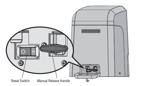
a. Reset switch is in the RESET position
b. Jumper is not in place for stop circuit
c. If on battery power only, low or dead batteries
d. Open or close input active
e. Entrapment protection device active
f. Vehicle loop detector or probe active
g. Inoperable control board
h. Inoperable motor or motor control module
|
a. Set reset switch to NORMAL OPERATION
b. Put a jumper on the stop circuit
c. Charges batteries by AC or solar power or replace batteries
d. Check all open and close inputs for a “stuck on” input
e. Check all entrapment protection device inputs for a “stuck on” sensor
f. Check all vehicle detector inputs for a “stuck on” detector
g. Replace inoperable control board
h. Replace motor or motor control module
|
| Gate moves, but cannot set correct limits. |
a. Gate does not move to a limit position
b. Gate is too difficult to move
c. Limits are set too close
|
a. Use manual disconnect, manually move gate, and ensure gate moves easily limit to limit. Repair gate as needed.
b. Gate must move easily and freely through its entire range, limit to limit. Repair gate as needed.
c. Ensure the gate moves at least four feet between the OPEN limit and the CLOSE limit.
|
| Gate does not fully open or fully close when setting limits |
a. Gate does not move to a limit position
b. Gate is too difficult to move
|
a. Use manual disconnect, manually move gate, and ensure gate moves easily limit to limit. Repair gate as needed.
b. Gate must move easily and freely through its entire range, limit to limit. Repair gate as needed.
|
| Operator does not respond to a wired control/command (example: open, close, SBC, etc.) |
a. Check open and close command input LEDs
b. Reset switch is in the RESET position
c. If on battery power only, low or dead batteries
d. Entrapment protection device active
e. Vehicle loop detector or vehicle probe active
|
a. Check all open and close inputs for a “stuck on” input
b. Set reset switch to NORMAL OPERATION, see page 31
c. Charges batteries by AC or solar power or replace batteries
d. Check all entrapment protection device inputs for a “stuck on” sensor
e. Check all vehicle detector inputs for a “stuck on” detector
|
| Operator does not respond to a wireless control or transmitter |
a. Check XMITTER LED when wireless control is active
b. Reset switch is in the off position
c. Poor radio reception
|
a. Activate wireless control and check XMITTER LED is on. Re-learn wireless control/transmitter to control board. Replace wireless control as needed.
b. Set reset switch to NORMAL OPERATION, see page 31
c. Check if similar wired control operates correctly. Check if wireless controls works properly when within a few feet of operator. Check operator’s antenna and antenna wire. Check other wireless controls or devices.
|
| Gate stops during travel and reverses immediately. |
a. Control (open, close) becoming active
b. Vehicle loop detector active
c. Low battery voltage
d. Inherent entrapment protection was activated while moving
|
a. Check all open and close inputs for an active input
b. Check all vehicle detector inputs for an active detector
c. Battery voltage must be 23 Vdc or higher. Charge batteries by AC or solar power or replace batteries
d. If there are no obstructions in gate path, manually disconnect the gate, and ensure it moves easily limit to limit. Repair gate as needed.
|
| Gate opens, but will not close with transmitter or Timer-to-Close. |
a. Open control active
b. Vehicle loop detector active
c. Loss of AC power with AC FAIL set to OPEN
d. Low battery with LOW BATT set to OPEN
e. Fire dept input active
f. Timer-to-Close not set
g. Close entrapment protection device active
|
a. Check all open inputs for an active input
b. Check all vehicle detector inputs for an active detector
c. Check AC power and AC Fail option setting
d. Check if AC power is available. If no AC power, then running on batteries and battery voltage must be 23 Vdc or higher. Charge batteries by AC or solar power or replace batteries.
e. Check Fire Dept input
f. Check Timer-to-Close (TTC) setting
g. Check all entrapment protection device inputs for an active sensor
|
| Gate closes, but will not open. |
a. Vehicle loop detector active
b. Low battery with LOW BATT option set to CLOSE
|
a. Check all vehicle detector inputs for an active detector
b. Check if AC power is available. If no AC power, then running on batteries and battery voltage must be 23 Vdc or higher. Charge batteries by AC or solar power or replace batteries.
|
| Exit loop activation does not cause gate to open. |
a. Exit vehicle detector setup incorrectly
b. Inoperable exit loop detector
c. Low battery with LOW BATT option set to CLOSE
|
a. Review exit loop detector settings. Adjust settings as needed.
b. Replace inoperable exit loop detector.
c. Check if AC power is available. If no AC power, then running on batteries and battery voltage must be 23 Vdc or higher. Charge batteries by AC or solar power or replace batteries.
|
| Interrupt loop does not cause gate to stop and reverse |
a. Vehicle detector setup incorrectly
b. Inoperable vehicle loop detector
c. Anti-tail set to ON
|
a. Review Interrupt loop detector settings. Adjust settings as needed.
b. Replace inoperable Interrupt loop detector.
c. Set anti-tail to OFF.
|
| Shadow loop does not keep gate at open limit. |
a. Vehicle detector setup incorrectly
b. Inoperable vehicle loop detector
|
a. Review shadow loop detector settings. Adjust settings as needed.
b. Replace inoperable shadow loop detector.
|
| Obstruction in gate's path does not cause gate to stop and reverse. |
a. Force adjustment needed |
a. Refer to the Adjustment section to conduct the obstruction test and perform the proper force adjustment that is needed. |
| Photoelectric sensor does not stop or reverse gate. |
a. Incorrect photoelectric sensor wiring
b. Inoperable photoelectric sensor
|
a. Check photoelectric sensor wiring. Retest that obstructing photoelectric sensor causes moving gate to stop, and may reverse direction.
b. Replace inoperable photoelectric sensor. Retest that obstructing photoelectric sensor causes moving gate to stop, and may reverse direction.
|
| Edge sensor does not stop or reverse gate. |
a. Incorrect edge sensor wiring
b. Inoperable edge sensor
|
a. Check edge sensor wiring. Retest that activating edge sensor causes moving gate to stop and reverse direction.
b. Replace inoperable edge sensor. Retest that activating edge sensor causes moving gate to stop and reverse direction.
|
| Alarm sounds for 5 minutes or alarm sounds with a command. |
a. Double entrapment occurred (two obstructions within a single activation) |
a. Check for cause of entrapment (obstruction) detection and correct. Press the reset button to shut off alarm and reset the operator. |
| Alarm beeps three times with a command. |
a. Low battery |
a. Check if AC power is available. If no AC power, then running on batteries and battery voltage must be 23 Vdc or higher. Charge batteries by AC or solar power or replace batteries |
| Alarm beeps when running. |
a. Expansion board setting
b. Constant pressure to open or close is given
|
a. Pre-warning is set to "ON"
b. Constant pressure to open or close is given
|
|
Expansion board function not controlling gate.
|
a. Inoperable main board to expansion board wiring
b. Incorrect input wiring to expansion board
c. Inoperable expansion board or inoperable main board
|
a. Check main board to expansion board wiring. If required, replace wire cable.
b. Check wiring to all inputs on expansion board.
c. Replace inoperable expansion board or main board
|
| Maglock not working correctly. |
a. Maglock wired incorrectly |
a. Check that maglock is wired to N.C. and COM terminals. Check that maglock has power (do not power maglock from control board accessory power terminals). If shorting lock’s NO and COM wires does not activate maglock, then replace maglock or maglock wiring (refer to wiring diagram). |
| Solenoid lock not working correctly. |
a. Solenoid wired incorrectly |
a. Check that solenoid is wired to N.O. and COM terminals. Check that solenoid has power (do not power solenoid from control board accessory power terminals). If shorting lock’s NC and COM wires does not activate solenoid, then replace solenoid lock or solenoid wiring (refer to wiring diagram). |
| Switched (SW) accessory power remaining on. |
a. In limit setup mode |
a. Learn the limits |
| Accessories connected to switched (SW) accessory power not working correctly, turning off, or resetting. |
a. Normal behavior |
a. Move accessory to accessory power "ON" |
| Accessories connected to Accessory power not working correctly, turning off, or resetting |
a. Accessory power protector active
b. Inoperable control board
|
a. Disconnect all accessory powered devices and measure accessory power voltage (should be 23 – 30 Vdc). If voltage is correct, connect accessories one at a time, measuring accessory voltage after every new connection.
b. Replace inoperable control board
|
| Quick close not working correctly. |
a. Quick close setting incorrect
b. Interrupt loop detector
c. Inoperable expansion board
|
a. Check that quick close setting is ON
b. Check operation of interrupt loop detector
c. Replace inoperable expansion board
|
| Anti-tailgating not working correctly. |
a. Anti-tail setting incorrect
b. Interrupt loop detector
c. Inoperable expansion board
|
a. Check that anti-tail setting is ON
b. Check operation of Interrupt loop detector
c. Replace inoperable expansion board
|
| AUX relay not working correctly. |
a. AUX relay setting incorrect
b. AUX relay wiring incorrect
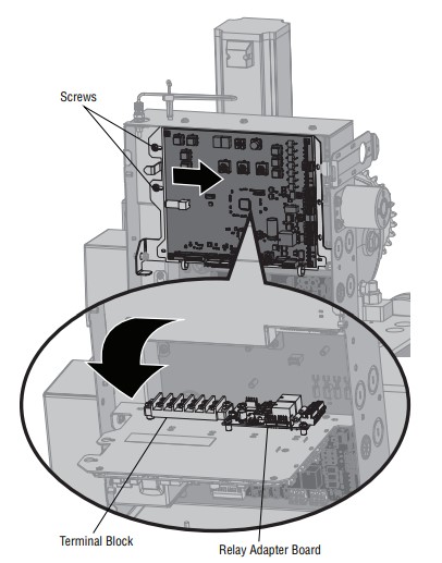
c. Inoperable expansion board or relay adapter board
|
a. Check AUX relay switches settings
b. Check that wiring is connected to either N.O. and COM or to N.C. and COM.
c. Set AUX relay to another setting and test. Replace inoperable expansion board or relay adapter board.
|
| Solar operator not getting enough cycles per day. |
a. Insufficient panel wattage
b. Excessive accessory power draw
c. Old batteries
d. Solar panels are not getting enough sunlight
|
a. Add more solar panels
b. Reduce the accessory power draw by using LiftMaster low power accessories
c. Replace batteries
d. Relocate the solar panels away from obstructions (trees, buildings, etc.)
|
| Solar operator, insufficient standby time. |
a. Insufficient panel wattage
b. Excessive accessory power draw
c. Battery capacity too low
|
a. Add more solar panels
b. Reduce the accessory power draw by using LiftMaster low power accessories
c. Use batteries with higher amp hour (AH) rating
|