A
B
B
B
C
E
F
D
G
G
G
G
H
12V Replacement Motor
Model 041D1624-2
Specifications
Volts ...................................120 Vac - 60 Hz, Only
Current ...........................................1.5 AMP
Rated Load ...................................385 in/ lb./sec.
Included Items
Motor and Bracket Assembly .............................. (1)
WARNING: This product can expose you to chemicals including
lead, which are known to the State of California to cause cancer or
birth defects or other reproductive harm. For more information go
to www.P65Warnings.ca.gov
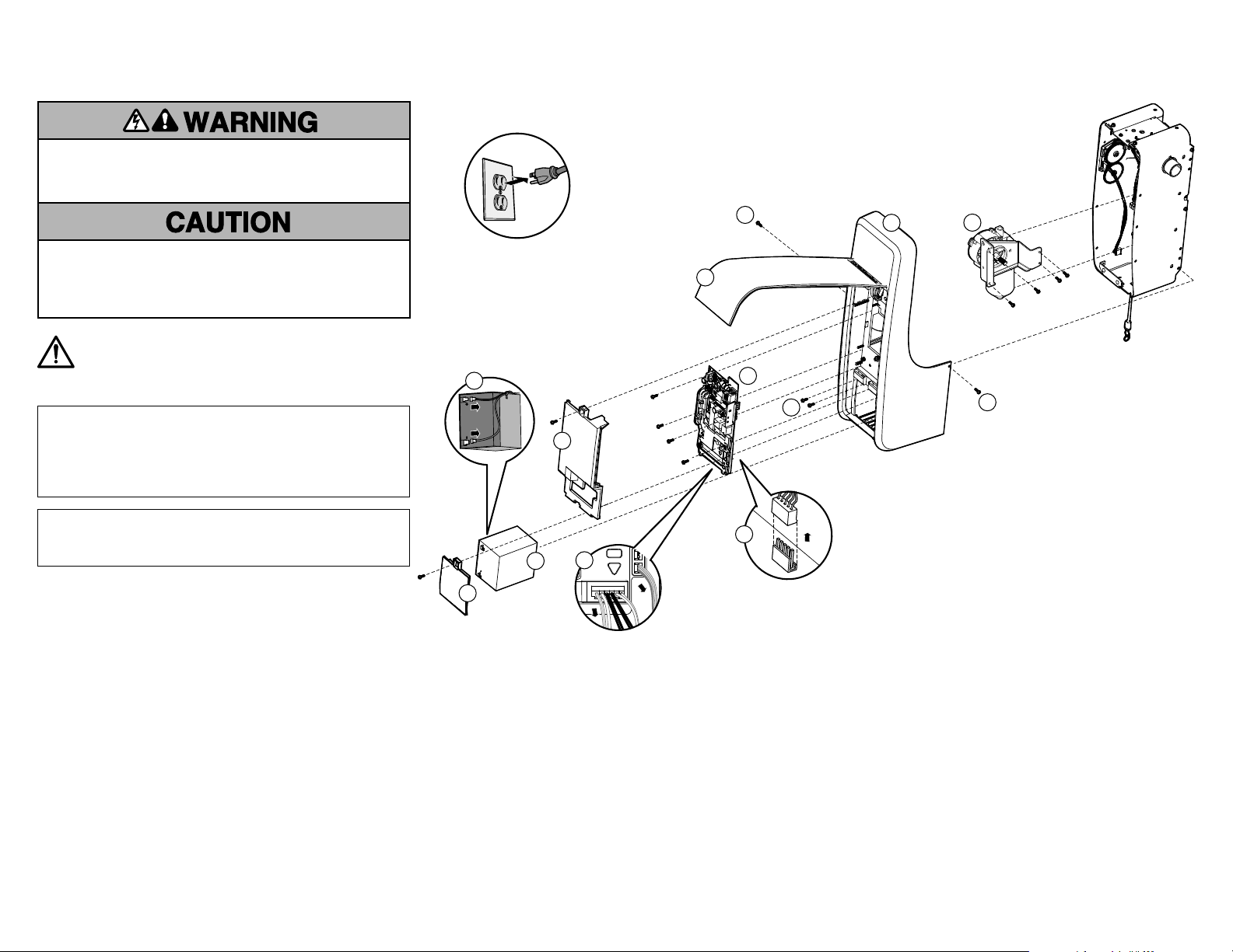
To prevent possible SERIOUS INJURY or DEATH:
• Disconnect ALL electric and battery power BEFORE performing ANY
service or maintenance.
To prevent damage to the receiver logic board, DO NOT touch printed
circuit board of replacement receiver logic board during installation.
ALWAYS wear protective gloves and eye protection when changing the
battery or working around the battery compartment.
9. Remove wires from the motor
bracket. Remove the E-Clip and
push clevis pin down, then remove
the 4 screws (5/16" and 1/4")
holding the motor in place (H).
10. Lift motor bracket up and off of
the clevis pin, remove chain from
motor sprocket and discard motor.
11. Reinstall new motor, ensure chain
is on unit sprocket, place chain
over motor sprocket, push clevis
pin into place, install C-clip. Fasten
motor down with 4 screws.
12. Reinstall the cover. Verify that the
tabs in the cover align with the
holes in the top of the chassis.
Route the wire harnesses and
wires through the cover (G).
13. Install the receiver logic board
and connect the wire harnesses.
Ensure the wire harnesses are
connected properly. Route the
antenna through the channel in the
cover. Install receiver logic board
cover.
14. Reconnect the wires to the quick
connect terminals (C).
15. Install the battery (if applicable)
and connect the battery
connectors. Install the battery
cover.
16. Reconnect power.
Refer to your manual to reset your
travel and force settings.
8. Remove the four screws
securing the cover to the
chassis (G).
6. Unplug the wire
harnesses from the
receiver logic board (E).
7. Remove the four screws
securing the receiver
logic board, remove and
discard (F).
4. Label wires for reinstallation.
Disconnect the wires from the quick
connect terminals (C).
NOTE: If there is a resistor located on
the green wire traps, do not remove.
5. Remove the receiver logic board
cover (D).
1. Disconnect power.
2. Open the front panel (A).
3. Remove the battery cover. Disconnect the
battery (if applicable). Remove the battery
and set aside (B).
5/16"
screws
1/4"
screws
1
Moteur de rechange de 12V
Modéle 041D1624-2
Données techniques
Volts ..............................120 Vca - 60 Hz, seulement
Courant...........................................1.5 AMP
Performance homologuée........................ 385 po/livre/s.
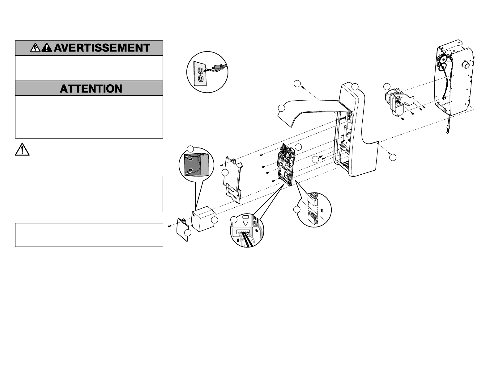
Pour prévenir d’éventuelles BLESSURES GRAVES ou LA MORT:
• Débrancher l’alimentation batterie et l’alimentation secteur AVANT
TOUTE réparation ou maintenance.
Pour empêcher tout dommage à la carte logique du récepteur, NE
touchez PAS au circuit imprimé de la carte logique du récepteur de
remplacement durant l’installation.
Munissez-vous TOUJOURS de gants de protection et de protection
pour les yeux quand vous travaillez sur une pile électrique ou sur un
compartiment de batterie.
AVERTISSEMENT : Ce produit peut vous exposer à des produits
chimiques comme le plomb, reconnu par l’État de la Californie
comme cause de cancers, d’anomalies congénitales et d’autres
problèmes liés à la reproduction. Pour plus d’informations, visitez
www.P65Warnings.ca.gov
A
B
B
B
C
E
F
D
G
G
G
G
H
9. Enlever les fils du support du
moteur. Enlever l’agrafe en E et
pousser l’axe de chape vers le bas,
puis enlever les quatre vis (5/16 de
po et 1/4 de po) qui retiennent le
moteur en place (H).
10. Lever le support du moteur vers
le haut et hors de l’axe de chape,
enlever la chaîne de la poulie du
moteur et jeter le moteur.
11. Installer le moteur neuf, s’assurer
que la chaîne sur la poulie, placer
la chaîne par-dessus la poulie,
pousser l’axe de chape en place
et installer l’agrafe en C. Fixer le
moteur en place avec les quatre vis.
12. Reposer le couvercle. Vérifier
que les pattes dans le couvercle
s’alignent sur les orifices sur le
dessus du châssis. Acheminer l
es faisceaux et les fils par le
couvercle (G).
13. Installer la carte logique du
récepteur et connecter les faisceaux
de fils. S’assurer que les faisceaux
de fils sont connectés correctement.
Réinstaller la carte logique et
connecter les faisceaux de câblage.
Installer le couvercle de la carte
logique du récepteur.
14. Raccorder les fils aux bornes à
raccordement rapide (C).
15. Installer la batterie (s’il y a lieu)
et connecter les connecteurs de
la batterie. Remettre en place le
couvercle de la batterie.
16. Reconnecter l’alimentation.
Consulter le manuel pour
réinitialiser les paramètres de
course et de force.
8. Enlever les quatre vis qui
retiennent le couvercle
du châssis (G).
6. Déconnecter les faisceaux
de fils de la carte logique du
récepteur (E).
7. Enlever les quatre fils qui
retiennent la carte logique
du récepteur, enlever la
carte logique et la jeter (F).
4. Étiqueter les fils pour la
réinstallation. Raccorder les fils aux
bornes à raccordement rapide (C).
REMARQUE: Si une résistance est
située sur les trappes de fil vert, ne
pas l’enlever.
5. Enlever le couvercle de la carte
logique du récepteur (D).
1. Débrancher l’alimentation électrique.
2. Ouvrir le panneau avant (A).
3. Remettre en place le couvercle de
la batterie. Déconnecter la batterie
(s’il y a lieu). Enlever la batterie et
la mettre de côté (B).
5/16
de po vis
1/4
de po vis
Articles inclus
Assemblage du moteur et du support........................ (1)
2
Motor de reemplazo de 12V
Modelo 041D1624-2
Especificaciones
Voltio............................120 V c.a. - 60 Hz, únicamente
Corriente..........................................1.5 AMP
Carga Clasificada.............................385 pulg./lib./seg.
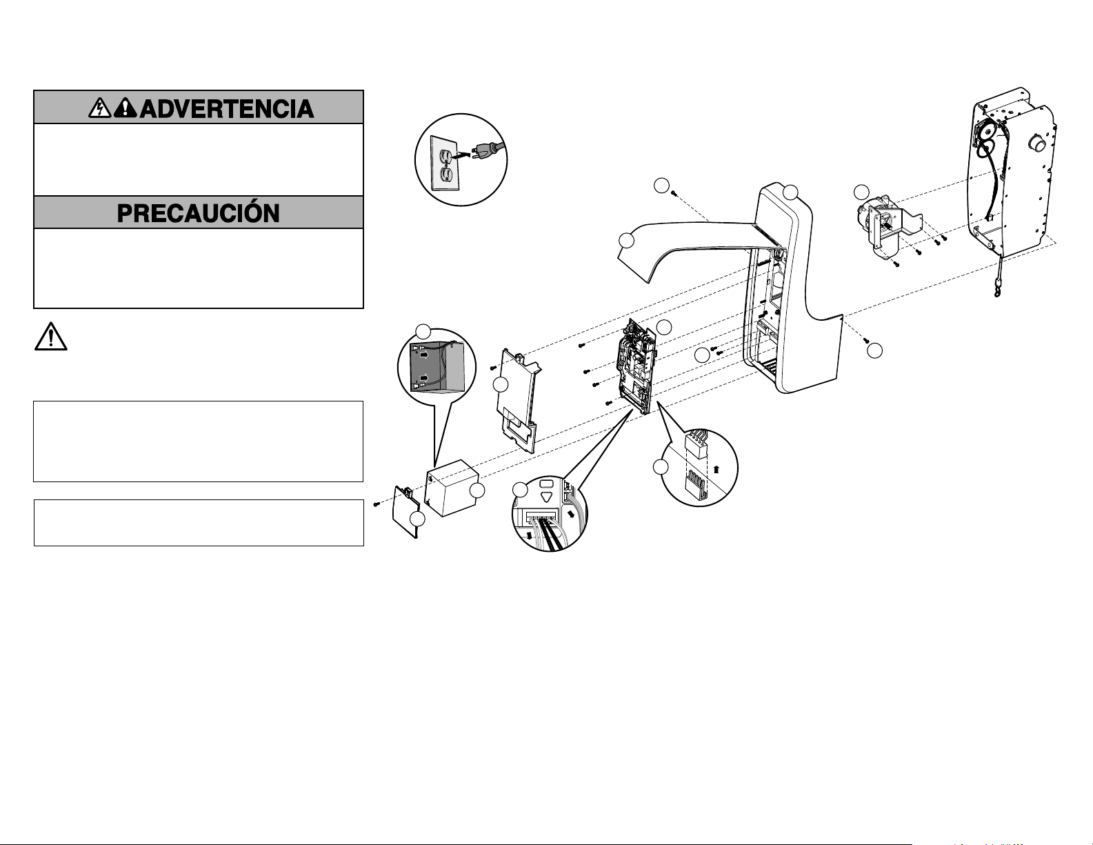
Para evitar la posibilidad de LESIONES GRAVES o INCLUSO LA
MUERTE:
• Desconecte TODA la corriente eléctrica y de la batería ANTES de
realizar cualquier servicio o mantenimiento.
Para evitar que se dañe la tarjeta lógica/el receptor, NO toque la tarjeta
de circuito impresa de la tarjeta lógica/del receptor de reemplazo
durante la instalación.
SIEMPRE uso los guantes protectores y protección ocular cuando
cambiar la batería o trabajando cerca el compartimiento de la batería.
ADVERTENCIA: Este producto puede exponerle a productos
químicos (incluido el plomo), que a consideración del
estado de California causan cáncer, defectos congénitos u
otros daños reproductivos. Para más información, visite
www.P65Warnings.ca.gov
A
B
B
B
C
E
F
D
G
G
G
G
H
9. Retire los cables de la ménsula
del motor. Retire el pasador en E
y presione el pasador de horquilla
hacia abajo, luego retire los cuatro
tornillos (5/16 de pulg. y 1/4 de
pulg.) manteniendo el motor en su
lugar (H).
10. Levante la ménsula del motor y
sáquela del pasador de horquilla,
retire la cadena del portacadena del
motor y deseche el motor.
11. Vuelva a instalar el nuevo motor,
asegúrese de que la cadena esté en
el portacadena de la unidad, coloque
la cadena en el pasador de horquilla
e introdúzcala en su lugar, instale
el pasador en C. Fije el motor hacia
abajo con cuatro tornillos.
12. Vuelva a colocar la cubierta.
Verifique que las lengüetas de la
cubierta estén alineadas con los
orificios de la parte superior del
chasis. Tienda los cables y los
arneses del cableado a través de la
cubierta (G).
13. Instale el tablero lógico del receptor
y conecte los arneses de cableado.
Asegúrese de que los arneses de
cableado estén correctamente
conectados. Coloque la antena
por el canal en la cubierta. Instale
la cubierta del tablero lógico del
receptor.
14. Vuelva a conectar los cables a los
terminales de conexión rápida (C).
15. Instale la batería (si corresponde)
y conecte los conectores de esta.
Instale la cubierta de la batería.
16. Vuelva a conectar la energía.
Consulte el manual para reiniciar
la configuración de fuerza y
desplazamiento.
8. Retire los cuatro tornillos
que sujetan la cubierta al
chasis (G).
6. Desenchufe los arneses
de cableado del tablero
lógico del receptor (E).
7. Retire los cuatro tornillos
que aseguran el tablero
lógico del receptor,
retírelo (F).
4. Etiquete los cables para la
reinstalación. Desconecte los
cables de los terminales de
conexión rápida (C).
NOTA: Si hay un resistor ubicado
en las trampas de alambre verde,
no lo retire.
5. Retire la cubierta del tablero
lógico del receptor (D).
1. Desconecte la energía eléctrica.
2. Abra el panel frontal (A).
3. Retire la cubierta de la batería.
Desconecte la batería (si
corresponde). Retire la batería y
colóquela a un costado (B).
5/16
de pulg.
tornillos
1/4
de pulg.
tornillos
Elementos que se incluyen
Ensamblaje de la ménsula y del motor ....................... (1)
3

© 2017, The Chamberlain Group, Inc.
All rights reserved
Tous droits réservés
114A5124 Todos los derechos reservados