User Manual Gate Operator
INTRODUCTION
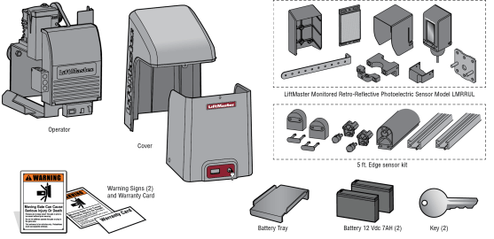
Carton Inventory
NOT SHOWN: Documentation Packet, Chain #41 - 30 feet, Eye Bolt Kit
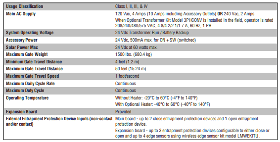
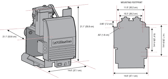
Operator Specifications
Site Preparation
Check the national and local building codes BEFORE installation
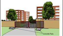
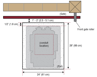
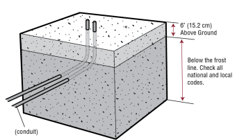
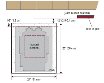
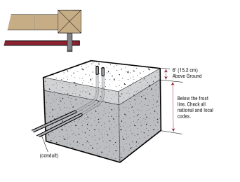
Conduit and Concrete Pad
Trench and install conduit. Before trenching, contact underground utility locating companies. Conduit must be UL approved for low and high voltage. Consider the operator placement BEFORE installing the pad or post.
Gate
Gate must be constructed and installed according to ASTM F2200 standards (refer to page 4). Gate must fit specifications of operator (refer to specifications).
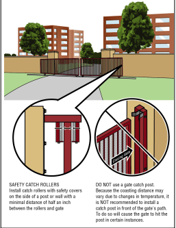
Safety
Entrapment protection devices are required to protect against any entrapment or safety conditions encountered in your gate application. Install a warning sign (two provided) on the inside and outside of the property, where easily visible

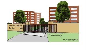
Additional Accessories
The vehicle loops allow the gate to stay open when vehicles are obstructing the gate path. Suggested for vehicles 14 feet (4.27 m) or longer. Vehicle loops are not required but are recommended. Before installing your Access Control Device(s) be sure to complete a site survey and determine the best device for your site needs.
INSTALLATION
Types of Installations
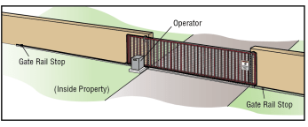
Standard Installation
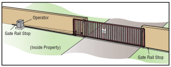
Rear Installation
Step 1 Determine Location for Operator
Check the national and local building codes before installation.
Standard Installation
1. The gate operator should be installed near the front roller of the gate. Lay out the concrete pad.
2. Install the electrical conduit.
3. Pour a concrete pad (reinforced concrete is recommended).
Rear Installation
1. The gate operator should be installed near the back of the gate in the OPEN position. Lay out the concrete pad.
2. Install the electrical conduit.
3. Pour a concrete pad (reinforced concrete is recommended).
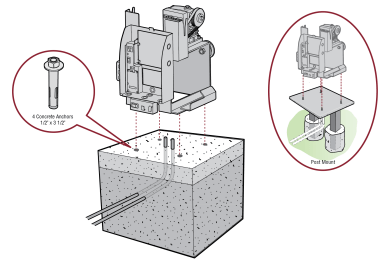
Step 2 Install the Operator
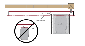
Attach the operator to the concrete pad with appropriate fasteners. The gate operator should be installed near the front roller of the gate or near the back of the gate (in the OPEN position). The space between the gate and the output sprocket must be a minimum of 4 inches (10.2 cm). NOTE: An alternative to a concrete pad is to post mount the operator (refer to Accessories).
Step 3 Attach the Chain
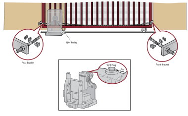
Standard Installation
DO NOT run the operator until instructed.
1. Manually open the gate and line up the front bracket so the chain will be level with the idler pulley and parallel to the ground. Weld the front bracket in this position.
2. Manually close the gate and line up the rear bracket so the chain will be level with the idler pulley and parallel to the ground. Weld the rear bracket in this position.
3. Route the chain through the operator.
4. Connect the chain to the brackets using the eye bolt hardware. Chain should not be too tight or have excessive slack.
5. Remove the pin from the vent plug on the gear box.
NOTE: The chain should have no more than 1 inch (2.5 cm) of sag for every 10 feet (3 m) of chain length.
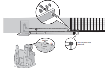
Rear Installation
DO NOT run the operator until instructed.
NOTE: This installation will require two extra idler pulleys. Make sure all exposed pinch points are guarded. Refer to Gate Construction Information on page 4.
1. Move the back pulley to the bottom hole in the operator.
2. Manually close the gate and align the bottom bracket so the chain will be level with the bottom idler pulley and parallel to the ground. Weld the bottom bracket in this position.
3. Align the top bracket so the chain will be level with the top idler pulley and parallel to the ground. Weld the upper bracket in this position.
4. Route the chain through the operator.
5. Connect the chain to the brackets using the eye bolt hardware. Chain should not be too tight or have excessive slack.
6. Remove the pin from the vent plug on the gear box.
NOTE: The chain should have no more than 1 inch (2.5 cm) of sag for every 10 feet (3 m) of chain length.
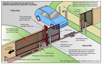
Step 4 Install Entrapment Protection
Entrapment protection MUST be installed according to the following UL 325 requirements:
- Slide gate operators require a minimum of two external monitored entrapment protection devices to function; one in the open direction and one in the close direction.
- Every installation is unique. It is the responsibility of the installer to ensure that ALL entrapment zones are protected with an external monitored entrapment protection device, protecting both the open and close gate cycles.
- LiftMaster monitored external entrapment protection devices MUST be used with LiftMaster operators to meet UL325 requirements, see Accessories.
- Test ALL entrapment protection devices after completing installation of the operator. For testing instructions, refer to the manual provided with your entrapment protection device.
Definitions
ENTRAPMENT: The condition when a person is caught or held in a position that increases the risk of injury.
SLIDE GATE ENTRAPMENT ZONE: An entrapment zone exists if at any point during travel, the gap between the gate and any opposing fixed edge or surface such as posts, walls, pillars, columns or operator itself, is less than 16" (406 mm) in a location up to 6 ft. (1.8 m) above grade.
Illustrations provided by DASMA Gate Systems Safety Guide
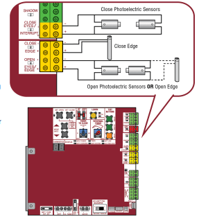
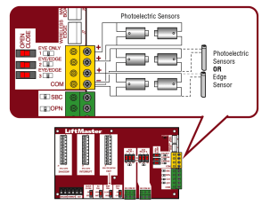
Wire Entrapment Protection Devices
There are three options for wiring the entrapment protection devices depending on the specific device and how the device will function. Refer to the specific entrapment protection device manual for more information. These entrapment protection device inputs are for monitored devices, which include pulsed photoelectric sensors, resistive edge sensors, and pulsed edge sensors. Only one monitored entrapment protection device may be wired to each input. Additional entrapment protection devices may be wired to the expansion board.
Control Board
CLOSES EYES/INTERRUPT
(2 Terminals) The CLOSE EYES/INTERRUPT input is for photoelectric sensor entrapment protection for the close direction. When an obstruction is sensed during gate closing the gate will open to the full open position and resets the Timer-to-Close. This input will be disregarded during gate opening.
CLOSE EDGE
(2 Terminals) The CLOSE EDGE input is for edge sensor entrapment protection for the close direction. When an obstruction is sensed during gate closing the gate will reverse to the full open position, disengaging the Timer-to-Close. This input will be disregarded during gate opening.
OPEN EYES/EDGE
(2 Terminals) The OPEN EYES/EDGE input is for photoelectric sensor or edge sensor entrapment protection for the open direction. When an obstruction is sensed during gate opening the gate will reverse for 4 seconds then stop. This input will be disregarded during gate closing.
Expansion Board
EYE ONLY and COM
Open or Close Direction Photoelectric Sensors, the functionality is based on the switch settings (located next to the terminals)
Switch set to CLOSE: gate reverses fully when an obstruction is sensed
Switch set to OPEN: gate reverses 4 seconds when an obstruction is sensed
EYE/EDGE and COM
Open or Close Direction Photoelectric Sensors or Edge Sensor, the functionality is based on the switch settings (located next to the terminals)
Switch set to CLOSE: gate reverses fully when an obstruction is sensed
Switch set to OPEN: gate reverses 4 seconds when an obstruction is sensed
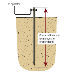
Step 5 Earth Ground Rod
Use the proper earth ground rod for your local area. The ground wire must be a single, whole piece of wire. Never splice two wires for the ground wire. If you should cut the ground wire too short, break it, or destroy its integrity, replace it with a single wire length.
1. Install the earth ground rod within 3 feet (.9 m) of the operator.
2. Run wire from the earth ground rod to the operator.
NOTE: If the operator is not grounded properly the range of the remote controls will be reduced and the operator will be more susceptible to lightning and surge damage.
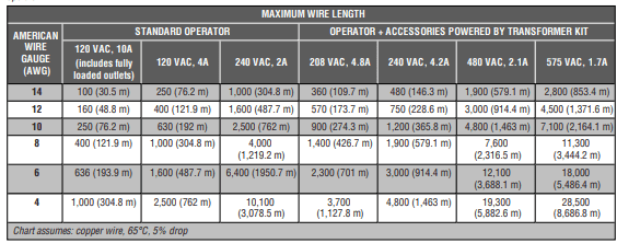
Step 6 Power Wiring
The operator can be wired for either 120 Vac or 240 Vac or a solar panel (not provided). Follow the directions according to your application. An optional Transformer Kit (Model 3PHCONV) can be used to change the input voltage (208/240/480/575 Vac) to an output voltage of 120 Vac (refer to Accessories). For dual gate applications, power will have to be connected to each operator. Main power supply and control wiring MUST be run in separate conduits. SOLAR APPLICATIONS: For solar applications refer to Solar Panels section in the Appendix. Follow the directions according to your application.
NOTE: If using an external receiver use shielded wire for the connections and mount the receiver away from the operator to avoid interference from the operato
All control wiring used to connect external devices to Class 2 circuits of the operator must be (QPTZ) Power-Limited Circuit Cables, Type CL2, CL2P, CL2R, or CL2X or other cable with equivalent or better electrical, mechanical, and flammability ratings.
240 VAC only
The accessory outlet is disabled and cannot be used with the 240 Vac option.
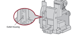
1. Remove the outlet housing from the electrical box by removing the screws (2).
2. Pull the outlet housing out and locate the power wiring connector on the EMI board.
3. Unplug the power wiring connector from the 120 Vac socket (factory default location) and plug it into the 240 Vac socket.
4. Replace the outlet housing by securing with the screws. The operator is now set for 240 Vac operation.
120 VAC and 240 VAC
1. Turn off the AC power from the main power source circuit breaker.
2. Run the AC power wires to the operator.
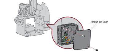
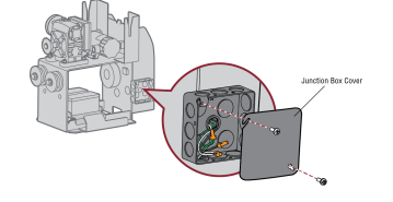
3. Remove the junction box cover.
4. Connect the green wire to the earth ground rod and AC ground using a wire nut. NOTE: The earth ground rod can be grounded to the chassis.
5. Connect the white wire to NEUTRAL using a wire nut.
6. Connect the black wire to HOT using a wire nut.
7. Replace the junction box cover. Ensure the wires are not pinched.
AC power switch
The AC Power switch on the operator will turn the incoming 120/240 Vac power ON or OFF. The operator's AC Power switch ONLY turns off AC power to the control board and DOES NOT turn off battery power.
Step 7 Connect Batteries
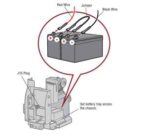
7AH battery
The batteries are charged in the circuit by the integrated transformer. The batteries are for battery backup.
1. Turn OFF AC power to the operator.
2. Unplug the J15 plug labeled BATT on the control board by squeezing the plug and pulling it from the control board. This disconnects the ac/dc power to the control board.
3. Connect a jumper between the positive (+) terminal of one battery to the negative terminal (-) of the other battery.
4. Connect the red wire from the J15 plug to the positive (+) terminal of the battery.
5. Connect the black wire from the J15 plug to the negative (-) terminal of the battery.
6. Plug the J15 plug back into the control board. This will power up the control board. NOTE: You may see a small spark when plugging the J15 plug into the board.
7. Turn ON AC power to the operator.
8. Turn ON the AC power switch on the operator.
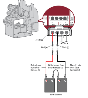
33AH battery
The batteries are charged in the circuit by the integrated transformer. The batteries are for battery backup or solar installation. The 33AH application requires the Solar Harness Kit (Model K94-37236) and an additional battery tray (Model K10-34758-2).
1. Locate the J15 plug on the control board and disconnect it.
2. Connect the white jumper from the Solar Harness Kit between the positive (+) terminal of one battery and the negative (-) terminal of the other battery.
3. Connect one end of the red (+) wire from the Solar Harness Kit to the red wire from the J15 plug as shown. Connect the other end of the red (+) wire to the positive (+) terminal on the battery as shown.
4. Connect one end of the black (-) wire from the Solar Harness Kit to the black wire from the J15 plug as shown. Connect the other end of the black (-) wire to the negative (-) terminal on the battery as shown.
5. Turn ON AC power to the operator.
6. Turn ON the AC power switch on the operator.
7. Reconnect the J15 plug to the control board.
NOTE: You may see a small spark when plugging the J15 plug into the board
Step 8 Dual gate setup
There are two options for dual gate communication: wired or wireless. Follow the directions according to your application. Do not use wired and wireless communication simultaneously. Wired dual gate applications will have a longer battery standby time than wireless applications.
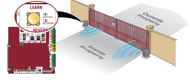
Wireless setup
To activate the wireless feature:
1. Choose an operator to be the network primary operator. All wireless accessories will need to be programmed to the primary operator. NOTE: We recommend that all accessories and board configurations are set on the primary operator.
2. Press and release the LEARN button on the primary operator. The green XMITTER LED will light. NOTE: The operator will time out of programming mode after 180 seconds.
3. Press and release the LEARN button again on the primary operator. The yellow NETWORK LED will light.
4. Press and release the OPEN test button to assign this operator as network primary.
5. Press and release the LEARN button on the second operator. The green XMITTER LED will light.
6. Press and release the LEARN button again on the second operator. The yellow NETWORK LED will light.
7. Press and release the CLOSE test button to assign this operator as network second.
Both operators will beep and the yellow NETWORK LEDs will turn off indicating programming is successful.
To deactivate the wireless feature:
1. Press and release the LEARN button on either operator. The green XMITTER LED will light.
2. Press and release the LEARN button again on the same operator. The yellow NETWORK LED will light.
3. Press and hold the LEARN button for 5 seconds. The yellow NETWORK LED will blink (operator will beep) then turn off indicating successful deactivation.
4. Repeat the steps for the other operator.
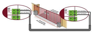
Wired setup
Before digging, contact local underground utility locating companies. Use PVC conduit to prevent damage to cables.

1. Disconnect ALL power to the operator and unplug the J15 plug from the control board.
2. Trench across driveway to bury the shielded twisted pair cable.
3. Connect the wires from the shielded twisted pair cable to the Com Link terminals on the primary gate operator control board. NOTE: We recommend that all accessories and board configurations are set on the primary operator.
4. Route the shielded twisted pair cable to the secondary gate operator's control board.
5. Connect the wires from the shielded twisted pair cable to the Com Link terminals on the secondary control board (Com Link A to Com Link A and Com Link B to Com Link B). Ground the shield of the cable to the chassis ground of one operator.
6. Connect ALL power to the operator and plug the J15 plug into the control board.
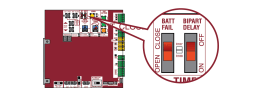
Bipart delay/synchronized close
The LOCK/BIPART DELAY switch is used only with dual gate applications and serves two functions:
SWING GATE APPLICATIONS: The BIPART DELAY is used in applications where a mag-lock, solenoid lock, or decorative overlay would require one gate to close before the other. The operator with the LOCK/BIPART DELAY switch ON will delay from the close limit when opening and be the first to close from the open limit. SLIDE GATE APPLICATIONS: Not applicable, set to OFF.
- SYNCHRONIZED CLOSE : The BIPART DELAY is also used in applications where one gate travels a longer distance than the other. To synchronize the closing of the gates, set the LOCK/BIPART DELAY switch to ON for both operators.
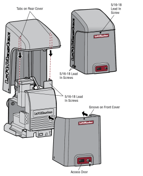
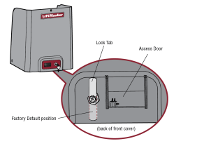
Step 9 Install the cover
Before installing the cover, follow the instructions in the Adjustment section to adjust the limits and force. The operator cover consists of two pieces: a rear cover and a front cover. The front cover can easily be removed to access the electrical box. To access the reset switch slide the access door up. The front cover and access door can be locked with the key.
1. Align the tabs on the rear cover with the slots on the chassis and place the cover over the operator.
2. Secure both sides of the rear cover to the chassis with two 5/16-18 lead in screws.
3. Align the front cover with the back cover, making sure the grooves line up.
4. Secure the front cover to the chassis with two 5/16-18 lead in screws.
5. Secure the front cover to the rear cover using the 5/16-18 lead in screw.
To Lock the Access Door
From the factory the access door for the reset switch will not be locked. To lock the access door follow the steps below:
1. Locate the lock tab on the back of the front cover and remove the screw securing the tab to the cover.
2. Turn the tab 180 degrees, then secure with the screw. The access door can now be locked.
ADJUSTMENT
Limit and Force Adjustment
Introduction
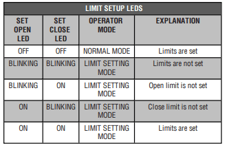
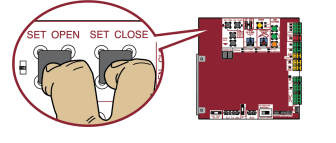
Your operator is designed with electronic controls to make travel limit and force adjustments easy. The adjustments allow you to program where the gate will stop in the open and close position. The electronic controls sense the amount of force required to open and close the gate. The force is adjusted automatically when you program the limits but should be fine tuned using the REVERSAL FORCE dial on the control board (refer to Fine Tune the Force section) to compensate for environmental changes. The limit setup LEDs (located next to the SET OPEN and SET CLOSE buttons) indicate the status of the limits, refer to the table to the right. The limits can be set using the control board (below) or a remote control (refer to Limit Setup with a Remote Control in the Appendix). Setting the limits with a remote control requires a 3-button remote control programmed to OPEN, CLOSE, and STOP.
NOTE: The TEST buttons on the control board will not work until the limits have been set and the required entrapment protection devices are installed.
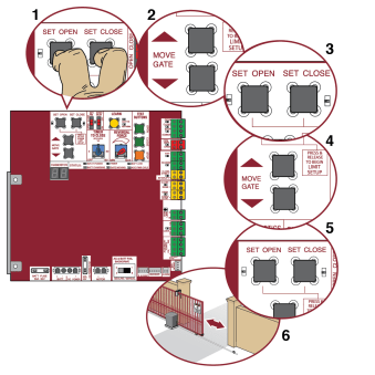
Initial Limits and Force Adjustment
For dual gate applications the limits will have to be set for each operator. The gate MUST be attached to the operator before setting the limits and force. For slide gate applications the open limit and closed limit MUST be set at least four feet apart.
1. Press and release the SET OPEN and SET CLOSE buttons simultaneously to enter limit setting mode.
2. Press and hold one of the MOVE GATE buttons to move the gate to the open or close limit.
3. Press and release the SET CLOSE or SET OPEN button depending on which limit is being set.
4. Press and hold one of the MOVE GATE button to move the gate to the other limit.
5. Press and release the SET CLOSE or SET OPEN button depending on which limit is being set.
6. Cycle the gate open and close. This automatically sets the force.
When limits are set properly the operator will automatically exit limit setting mode
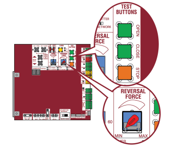
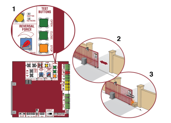
Fine Tune the Force
Once the initial limits have been set, the REVERSAL FORCE DIAL on the control board is used for fine tuning the force where wind or environmental changes may affect the gate travel. The REVERSAL FORCE DIAL is set to minimum at the factory. Based on the length and weight of the gate it may be necessary to make additional force adjustments. The force setting should be high enough that the gate will not reverse by itself nor cause nuisance interruptions, but low enough to prevent serious injury to a person. The force setting is the same for both the open and close gate directions.
1. Open and close the gate with the TEST BUTTONS.
2. If the gate stops or reverses before reaching the fully open or closed position, increase the force by turning the force control slightly clockwise.
3. Perform the “Obstruction Test” after every limit and force setting adjustment (see below).
Adjust the Limits
After both limits are set and the operator is ready to run, one limit can be adjusted independently from the other by following steps 1-3 of the Initial Limit and Force Adjustment section.
Obstruction Test
The operator is equipped with an inherent (built in to the operator) obstruction sensing device. If the gate encounters an obstruction during motion, the operator will reverse direction of the gate and then stop. The following procedure will test ONLY the inherent (built in to the operator) obstruction sensing device:
1. Open and close the gate with the TEST BUTTONS, ensuring that the gate is stopping at the proper open and close limit positions.
2. Place an object between the open gate and a rigid structure. Make sure that any external entrapment protection devices will NOT be activated by the object.
3. Run the gate in the close direction. The gate should stop and reverse upon contact with the object. If the gate does not reverse off the object, reduce the force setting by turning the force control slightly counter-clockwise. The gate should have enough force to reach both the open and close limits, but MUST reverse after contact with an object.
4. Repeat the test for the open direction.
Test the operator after any adjustments are made.
PROGRAMMING
Remote Controls (Not Provided)
A total of 50 Security+ 2.0® remote controls or KPW250 keypads and 2 keyless entries (1 PIN for each keyless entry) can be programmed to the operator. When programming a third keyless entry to the operator, the first keyless entry will be erased to allow the third keyless entry to be programmed. When the operator’s memory is full it will exit the programming mode and the remote control will not be programmed. The memory will need to be erased before programming any additional remote controls.
NOTE: If installing an 86LM to extend the range of the remote controls DO NOT straighten the antenna.
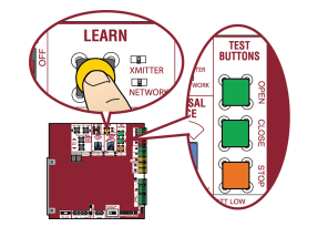
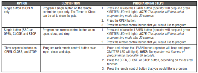
There are 3 different options for programming the remote control depending on how you would like the remote control to function. Choose a programming option:
The operator will automatically exit learn mode (operator will beep and green XMITTER LED will go out) if programming is successful. To program additional Security+ 2.0® remote controls or remote control buttons, repeat the programming steps above.
Entering programming mode using external reset button or 3-button control station:
1. Make sure gate/door is closed.
2. Give the operator an OPEN command.
3. Within 30 seconds, when the gate/door is at the open limit press and release the RESET/STOP button twice to put the operator into programming mode.
NOTE: The operator will time out of programming mode after 30 seconds.
LiftMaster Internet Gateway (not provided)
To program the operator to the LiftMaster Internet Gateway:
Using the learn button on the opertaor's control board
1. Connect the ethernet cable to the LiftMaster Internet Gateway and the router.
2. Connect power to the LiftMaster Internet Gateway.
3. Create an online account by visiting www.myliftmaster.com.
4. Register the LiftMaster Internet Gateway.
5. Use an internet enabled computer or smartphone to add devices. The LiftMaster Internet Gateway will stay in learn mode for three minutes.
6. Press the Learn button twice on the primary operator (the operator will beep as it enters learn mode). The LiftMaster Internet Gateway will pair to the operator if it is within range and the operator will beep if programming is successful.
Using the reset button on the operator
1. Connect the ethernet cable to the LiftMaster Internet Gateway and the router.
2. Connect power to the LiftMaster Internet Gateway.
3. Create an online account by visiting www.myliftmaster.com.
4. Register the LiftMaster Internet Gateway.
5. Use an internet enabled computer or smartphone to add devices. The LiftMaster Internet Gateway will stay in learn mode for three minutes.
6. Ensure gate is closed.
7. Give the operator an OPEN command.
8. Within 30 seconds, when the gate is at the open limit press and release the reset button 3 times (on primary gate) to put primary operator into High Band Learn Mode (the operator will beep as it enters learn mode). The LiftMaster Internet Gateway will pair to the operator if it is within range and the operator will beep if programming is successful.
The status as shown by the LiftMaster Internet Gateway app will be either “open” or “closed”. The gate operator can then be controlled through the LiftMaster Internet Gateway app.
Erase All Codes
1. Press and release the LEARN button (operator will beep and green XMITTER LED will light).
2. Press and hold the LEARN button again until the green XMITTER LED flashes and then release the button (approximately 6 seconds). All remote control codes are now erased.
Erase Limits
1. To erase the limits, press and hold the SET OPEN and SET CLOSE buttons simultaneously (5 seconds) until both the SET OPEN and SET CLOSE LEDs blink rapidly and the operator beeps.
2. Release the buttons and the SET OPEN and SET CLOSE LEDs will blink slowly indicating the limits will need to be set.
Constant Pressure Override (CPO)
Constant Pressure Override is for use with KPW5 and KPW250 keypads (not provided). The KPW5/KPW250 wireless commercial keypads are security keypads and can only be programmed to ONE gate operator (see the KPW5/KPW250 manual for complete programming instructions). The Constant Pressure Override feature is intended to temporarily override a fault in the entrapment protection system, in order to operate the gate until the external entrapment protection device is realigned or repaired. Use the feature only in line of sight of the gate when no obstructions to travel are present. External entrapment protection devices include LiftMaster monitored photoelectric sensors and LiftMaster monitored wired and wireless edge sensors. Be sure to repair or replace these devices promptly if they are not working properly.
To use Constant Pressure Override:
1. Enter a valid 4-digit PIN.
2. Press and hold # for 5 seconds to enter CPO. Continue to hold # to keep the operator in motion. A continuous tone will sound until limit is met and/or # is released.
3. The operator will stop when either the operator reaches a limit or the user releases #.
Gate Hold Open Feature
The gate hold open feature will disable the timer and keep the gate at the open limit. The gate hold open feature can be activated through the Reset Button as described on Page 29 or through the KPW5 and KPW250 keypads (not provided).
To use the gate hold open feature:
1. Enter a valid 4-digit PIN when the gate is at the Open Limit and the timer is running
2. The Operator will chirp indicating the timer is canceled.
To restart the gate:
1. Re-enter the 4-digit PIN
2. Activate a Hard input or a programmed remote
To Remove and Erase Monitored Entrapment Protection Devices
1. Remove the entrapment protection device wires from the terminal block.
2. Press and release the SET OPEN and SET CLOSE buttons simultaneously. The SET OPEN and SET CLOSE LEDs will turn on (entering learn limit mode).
3. Press and release both SET OPEN and SET CLOSE buttons again to turn off the SET OPEN and SET CLOSE LEDs (exiting learn limit mode).
OPERATION
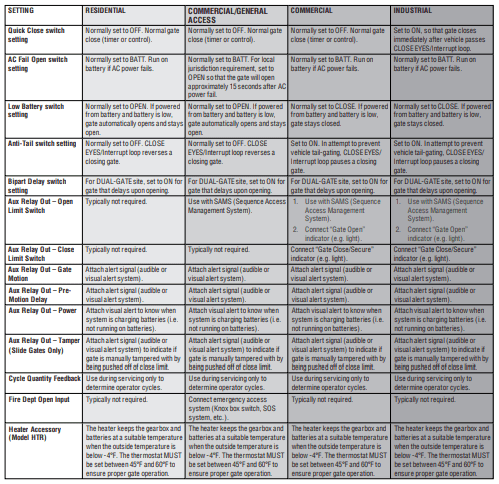
Gate operator setup examples
The following are example setups for the gate operator. Your specific site requirements may be different. Always setup the operator system to the site requirements, including all necessary entrapment protection devices.
RESIDENTIAL: One to four residential homes sharing a gated entrance/exit, allowing vehicle access trumps security concerns
COMMERCIAL/GENERAL ACCESS: A residential community (more than four homes) having one or more gated entrances/exits, allowing vehicle access trumps security concerns
COMMERCIAL: Business site where security (gate closed) is important
INDUSTRIAL: Large business site where security is required
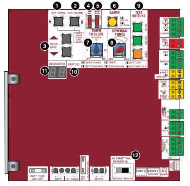
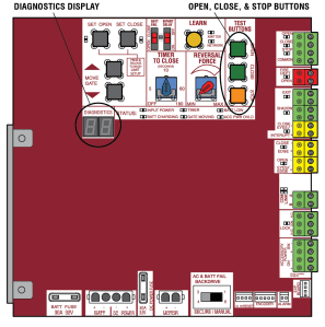
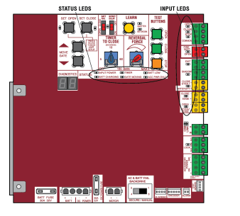
Control Board Overview
1 SET OPEN Button: The SET OPEN button sets the OPEN limit. See Adjust Limits section.
2 SET CLOSE Button: The SET CLOSE button sets the CLOSE limit. See Adjust Limits section.
3 MOVE GATE Buttons: The MOVE GATE buttons will either open or close the gate when the operator is in Limit setting mode. See Adjust Limits section.
4 BATT FAIL:
- When AC power is OFF and battery voltage is critically low the gate will latch at a limit until AC power is restored or batteries voltage increases.
- Option select switch set to OPEN forces gate to automatically open and then latch at the OPEN limit until AC power is restored or battery voltage increases.
- Option select switch set to CLOSE forces gate to latch at CLOSE limit if at CLOSE limit or on next CLOSE command until AC power restored or battery voltage increases.
- Constant pressure on a hard command input overrides to open or close the gate.
- Critically low battery is less than 23 V
5 BIPART DELAY Switch: The LOCK/BIPART DELAY switch is used only for dual gates. See Bipart Delay section.
6 LEARN Button: The LEARN button is for programming remote controls and the network.
7 TIMER-TO-CLOSE dial: The TIMER-TO-CLOSE (TTC) dial can be set to automatically close the gate after a specified time period. The TTC is factory set to OFF. If the TTC is set to the OFF position, then the gate will remain open until the operator receives another command from a control. Rotate the TIMER-TOCLOSE dial to the desired setting. The range is 0 to 180 seconds, 0 seconds is OFF. NOTE: Any radio command, single button control, or CLOSE command on the control board prior to the TTC expiring will close the gate. The TTC is reset by any signals from the open controls, loops, close edges, and close photoelectric sensors (IR’s).
8 REVERSAL FORCE dial: The REVERSAL FORCE dial fine tunes the force. See Force Adjustment section.
9 TEST BUTTONS: The TEST BUTTONS will operate the gate (OPEN, STOP and CLOSE).
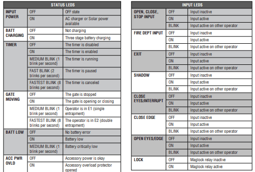
10 STATUS LEDs: The STATUS LEDs indicate the status of the operator. See Status LED Chart in the Troubleshooting section.
11 DIAGNOSTICS Display: The diagnostics display will show the operator type, firmware version, and codes. The operator type will display as "SL" followed by a "24" which indicates the operator type as CSL24UL. The firmware version will show after the operator type, example "1.2".
12 BACKDRIVE Switch: Set to MANUAL will allow the gate to be manually pushed open or closed if there is a loss of AC and battery power. Set to SECURE makes the gate difficult to push open or closed if there is a loss of AC and battery power
Manual Disconnect
Press the reset switch to RESET/DISCONNECT. Release the handle on the operator arm to allow the gate to be opened and closed manually. On a dual gate application the handle must be released on both operators. To resume normal function tighten the handle by pushing it down.
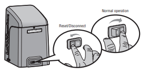
Reset Switch
The reset switch is located on the front of the operator and serves several functions. Toggling the reset switch will stop a moving gate during a normal open/ close cycle, like a stop button. The operator does not need to be reset after doing this. The reset switch will disable the gate in the present position and will energize the solenoid lock for two minutes and disable the maglock for two minutes.
Operator Alarm
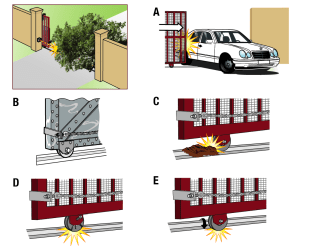
If a contact sensor detects an obstruction twice consecutively the alarm will sound (up to 5 minutes) and the operator will need to be reset. When the inherent force of the operator (RPM/current sensor) detects the following (twice consecutively) the alarm will sound (up to 5 minutes) and the operator will need to be reset.
A. The gate is hitting a wall or vehicle.
B. The gate does not meet specifications.
C. Debris is on the gate's track such as mud, rocks, dirt, etc.
D. The gate has one or more broken axles or wheels.
E. The gate wheel is off the gate rail.
Remove any obstructions. Press the reset button to shut off the alarm and reset the operator. After the operator is reset, normal functions will resume.
The operator alarm will beep 3 times with a command if the battery is low.
Remote control
Single Button Control (SBC) Functionality
Once the remote control has been programmed the operator will operate as follows: When gate is in the closed position, activation of the remote control button will open the gate. During the open cycle another activation of the remote control will stop the gate and the next activation of the remote control will close the gate. When the gate is in the open position, activation of the remote control button will close the gate. If the remote control is activated while the gate is closing, the gate will stop and the next activation will open the gate.
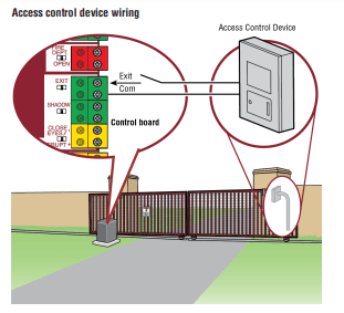
ACCESSORY WIRING
All control wiring used to connect external devices to Class 2 circuits of the operator must be (QPTZ) Power-Limited Circuit Cables, Type CL2, CL2P, CL2R, or CL2X or other cable with equivalent or better electrical, mechanical, and flammability ratings.
External control devices
EXIT (2 Terminals)
This input is a soft open command (maintained switch does not override external safeties and does not reset alarm condition). Used for exit probe, telephone entry, external exit loop detector, or any device that would command the gate to open.
- Opens a closing gate and holds open an open gate, if maintained, pauses Timer-to-Close at OPEN limit.
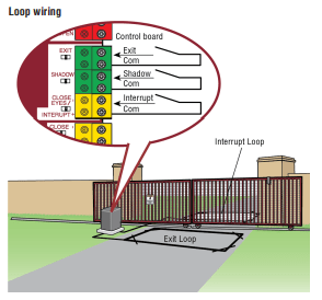
SHADOW (2 Terminals)
This input is used for external shadow loop detector when loop is positioned under the swing of the gate.
- Holds open gate at open limit
- Only active when the gate is at the OPEN limit, disregarded at all other times
- Pauses Timer-to-Close at OPEN limit
INTERRUPT (2 Terminals)
This input is used for photoelectric sensors and external interrupt loop detector when loop is on the outside of the gate.
- Holds open gate at open limit
- Stops and reverses a closing gate to open limit
- Pauses Timer-to-Close at OPEN limit, activates quick close and antitailgate features when enabled on the expansion board
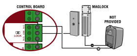
Locks
Maglock (2 Terminals, N.C. and COM)
Relay contact output, Normally - closed (N.C.) output for maglocks. Relay activates prior to motor activation and during motor run. Relay is off when motor is off.
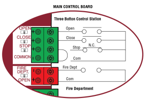
Miscellaneous wiring
Three button control station (4 Terminals)
- OPEN and COM: Opens a closed gate. Hard open (maintained switch overrides external safeties and resets alarm condition). If maintained, pauses Timer-to-Close at OPEN limit. Opens a closing gate and holds open an open gate (within line-of-sight).
- CLOSE and COM: Closes an open gate. Hard close (maintained switch overrides external safeties and resets alarm condition within line-of-sight)
- STOP and COM: Stops a moving gate. Hard stop (maintained switch overrides Open and Close commands and resets alarm condition). If maintained, pauses Timer-to-Close at OPEN limit. Overrides Open and Close commands (within line-of-sight).
Fire department open input (2 Terminals)
Acts as hard open. Maintained input overrides (ignores) external safeties (photoelectric sensor and edge), pauses Timer-to-Close momentary input logic as single button control and safeties remain active, re-enables Timer-to-Close.
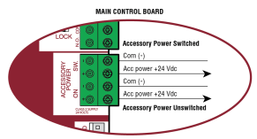
Accessory power 24 VDC, MAX 500 mA (4 Terminals)
- SWITCHED: Switched ON with gate motion and at the open limit when Timer-to-Close is active. Turns off 5 seconds after motion.
- UNSWITCHED: 24 Vdc voltage out to power accessories, always ON.
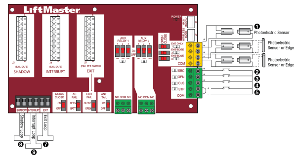
EXPANSION BOARD
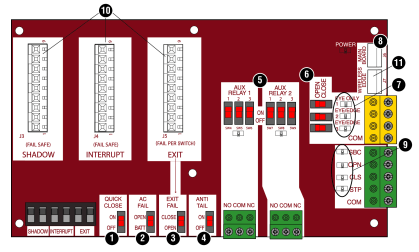
Expansion board overview
1. QUICK CLOSE switch:
OFF: No change to the gate's normal operation.
ON: When CLOSE EYES/Interrupt loop is deactivated it causes an opening or a stopped gate to close (ignores the Timer-to-Close).
2. AC FAIL switch:
OPEN: Loss of AC power will cause the gate to open approximately 15 seconds after AC power fail and remain OPEN until AC power is restored (enabling the Timer-to-Close). BATT: With loss of AC power, gate will remain in present position and operator is powered from batteries.
3. EXIT FAIL switch:
When set to OPEN, if the EXIT plug-in loop detector (Model LOOPDETLM) detects a fault, then the gate will open and remain open until fault is cleared. When set to CLOSE, then plug-in EXIT loop detector faults are ignored (EXIT loop is faulted and inoperative).
4. ANTI-TAIL switch:
OFF: When CLOSE EYES/Interrupt loop is activated it causes a closing gate to stop and reverse. ON: When CLOSE EYES/Interrupt loop is activated it causes a closing gate to pause. Once the vehicle is clear the gate will continue to close.
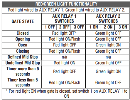
5. AUX RELAY switches:
Set the AUX RELAY switches as needed to obtain the desired function as shown on the following page.
6. EYE/EDGE switches:
Set the EYE/EDGE switches as needed to obtain the desired OPEN or CLOSE functionality.
7. 1, 2, and 3 LEDs:
LEDs indicating the status of the EYE/EDGE inputs. Also used to check the firmware version of the expansion board:
1. Locate the 1, 2, and 3 LEDs on the expansion board.
2. Disconnect AC/DC power to the main control board for 15 seconds.
3. Connect power. The 1, 2, and 3 LEDs will flash in sequence until the main control board firmware revision is displayed. When the green POWER LED glows solid the LED 1 will flash the version number, then stop, then the LED 2 will flash the revision number (for example: For version 5.1 when the green POWER LED is solid the LED 1 will flash 5 times, then stop, then the LED 2 will flash once).
8. MAIN BOARD input:
Input Connection for the main board connector.
9. Input LEDs:
LEDs indicating the status of the SBC, OPN, CLS, and STP inputs.
10. Loop detector inputs:
Inputs for the Plug-In Loop Detectors (Model LOOPDETLM)
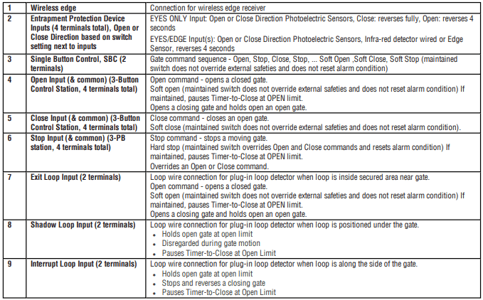
11. Wireless edge input:
Input for the Wireless Edge Kit (Model LMWEKITU)
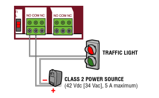
Auxiliary relay 1 and 2
Normally Open (N.O.) and Normally Closed (N.C.) relay contacts to control external devices, for connection of Class 2, low voltage (42 Vdc [34 Vac] max 5 Amps) power sources only. Function of relay contact activation determined by switch settings.
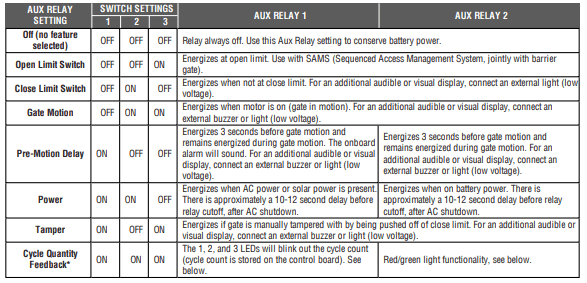
* Cycle count
First, note the current Aux Relay switch positions. To determine the actual cycles that the gate operator has run (in thousands), set all three Aux Relay switches to the ON setting for Aux Relay 1. The Expansion Board’s 1, 2, and 3 LEDs will blink out the cycle count, with 1 LED blinking 1000’s, 2 LED blinking 10,000’s, 3 LED blinking 100,000’s, and simultaneously all three LED’s blink 1,000,000’s (e.g. 1 LED blinks 3 times, 2 LED blinks 6 times, and 3 LED blinks once. Cycle count is 163,000.). Cycle count displayed is between 1,000 and 9,999,000 cycles. After servicing, set Aux Relay switches back to their appropriate positions. Cycle count cannot be reset or changed. If under 1,000 cycles the 1, 2, and 3 LEDs will turn on for 10 seconds, then turn off.
NOTE: The expansion board will flash the cycle count 3 times then all the LEDs will turn on solid for 10 seconds then turn off.
Auxiliary relay wiring example
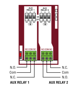
Wiring accessories to the expansion board
Refer to the chart below and the corresponding image for a description of the expansion board inputs.
MAINTENANCE
Maintenance Chart
Disconnect all power (AC, solar, battery) to the operator before servicing. The operator's AC Power switch ONLY turns off AC power to the control board and DOES NOT turn off battery power. ALWAYS disconnect the batteries to service the operator.
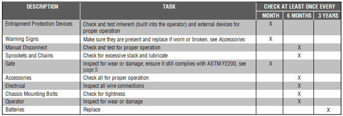
NOTES:
- Severe or high cycle usage will require more frequent maintenance checks.
- Limits may have to be reset after any major drive chain adjustments.
- If lubricating chain, use only lithium spray. Never use grease or silicone spray.
- It is suggested that while at the site voltage readings be taken at the operator. Using a digital voltmeter, verify that the incoming voltage to the operator is within ten percent of the operator’s rating.
Batteries
Batteries will degrade over time depending on temperature and usage. The operator alarm will beep 3 times with a command if the battery is low. Batteries do not perform well in extremely cold temperatures. For best performance, the batteries should be replaced every 3 years. Use only LiftMaster part 29-NP712 for replacement batteries. The batteries contain lead and need to be disposed of properly. The operator comes with two 7AH batteries. Two 33AH batteries (A12330SGLPK), with Solar Harness Kit (K94-37236) may be used in place of the 7AH batteries.
Drive Train
Over time, the drive chain on the operator will stretch and need to be tightened. To tighten the drive chain adjust either of the two chain eye bolts. NOTE: The chain should have no more than 1 inch of sag for every 10 feet of chain length.
TROUBLESHOOTING
Diagnostic Codes
To View the Codes
The codes will show on the diagnostic display.
The operator will show the code sequence number followed by the code number:

To Scroll Through the Saved Codes
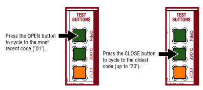
The operator will only keep track of up to 20 codes, then will start saving over the oldest codes as new codes occur
To Exit
Press and release the STOP button to exit. The display will also time out after two minutes of inactivity.
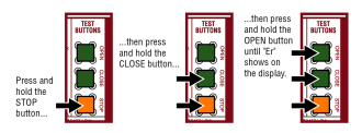
To Reset the Code History
1. Press and hold the STOP button for six seconds. The display will show "Er" then "CL" alternately for six seconds.
2. Release the STOP button. The code history has now been reset and the display will show "- -" until a new code occurs.
3. Press and release the STOP button to exit.
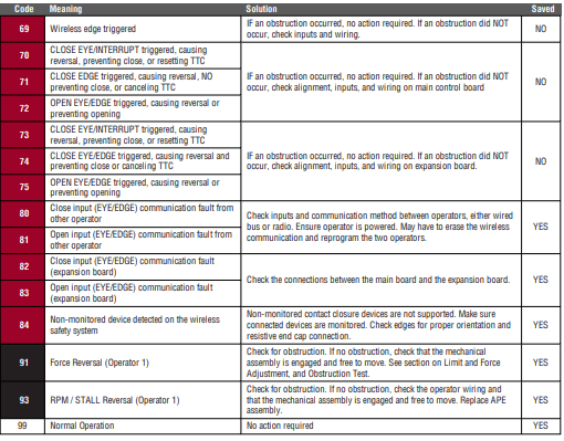
Diagnostic Codes Table
Some codes are saved in the code history and some are not. If a code is not saved it will briefly appear on the display as it occurs, then disappear.
 LiftMaster System
 Installed System
 Informational
 External Entrapment Protection
 Inherent Entrapment Protection

Control Board LEDs
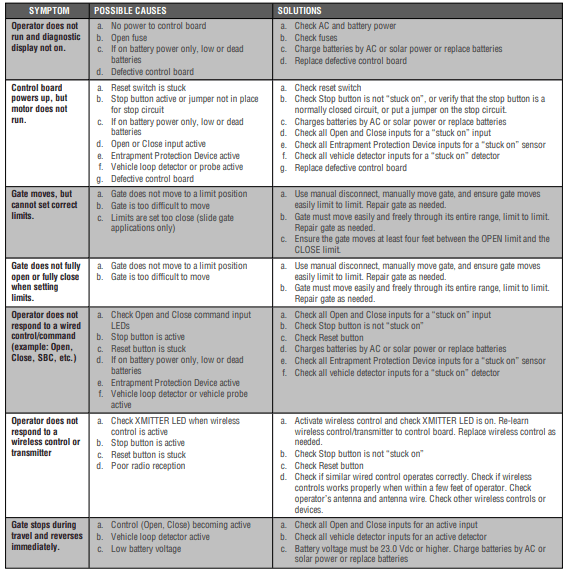
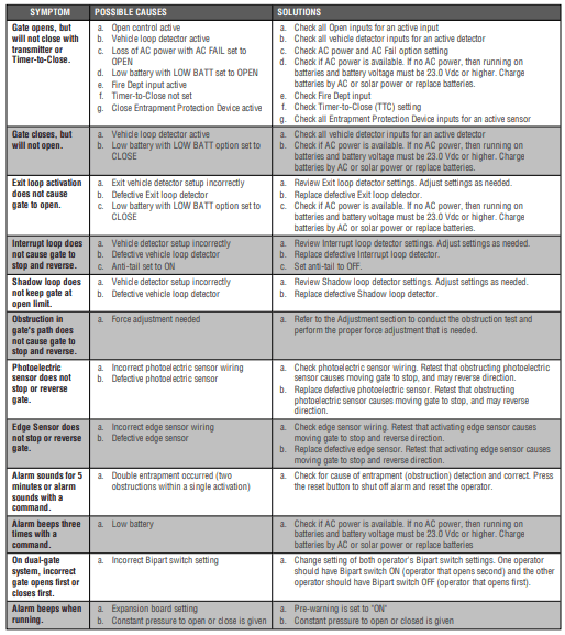
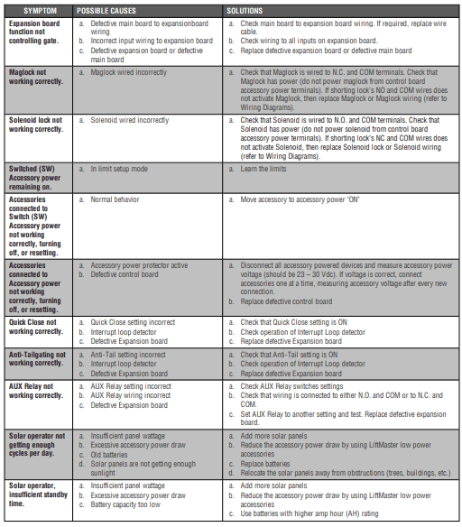
Troubleshooting Chart