If this operator is a replacement for a Miracle-One™ operator, use the existing post bracket and gate bracket. Remove the Miracle-One™ operator from the brackets and proceed to the next step. If your application is Push-to-Open, refer to the illustrations in the Appendix.
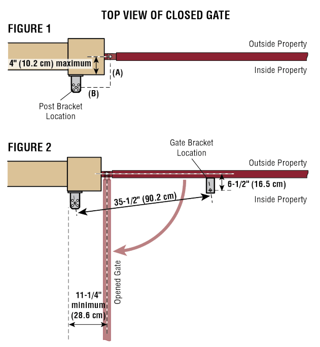
The measurements shown below are typical for a standard installation. Your installation may be different. The gate bracket MUST be installed in an area that can withstand heavy forces. Additional reinforcement steel plates may be necessary for mounting.
1. Close the gate.
2. Choose a vertical mounting location for the post bracket. 3. Place a measuring tape under the center of the gate hinge point and measure out dimension A (see chart).
4. Use a screwdriver or dowel rod to temporarily mark the location of the first measurement (Figure 1).
5. Measure out dimension B (see chart) from the previous mark. Use a screwdriver to mark the location of the second measurement (Figure 1).
6. Align the post bracket as close as possible above the screwdriver or dowel rod and tack weld the post bracket in the desired vertical position.
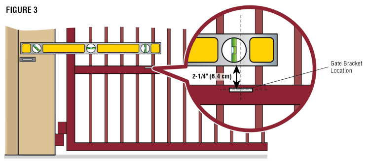
7. Position a level on the post bracket and measure 35-1/2" (90.2 cm) over from the center hole of the post bracket and mark the location on the gate (Figure 2).
8. Measure 2-1/4" (6.4 cm) down from the previous mark and center the bracket on this mark (Figure 3). Tack weld the gate bracket in this position.
NOTES:
● There should only be a maximum of 4" (10.2 cm) from the center of the hinge to the edge of the post or column (Figure 1). If the distance is greater than 4" (10.2 cm) entrapment protection for this area is required.
● While the gate is in the fully open position, the operator needs a clearance of 11-1/4" (28.6 cm) as shown (Figure 2).
NOTE: The ideal installation measurements are A = 7-3/4" (19.7 cm) and B = 8- 1/2" (21.6 cm). If different measurements are used, the sum of A and B cannot be greater than 18" (45.7 cm).
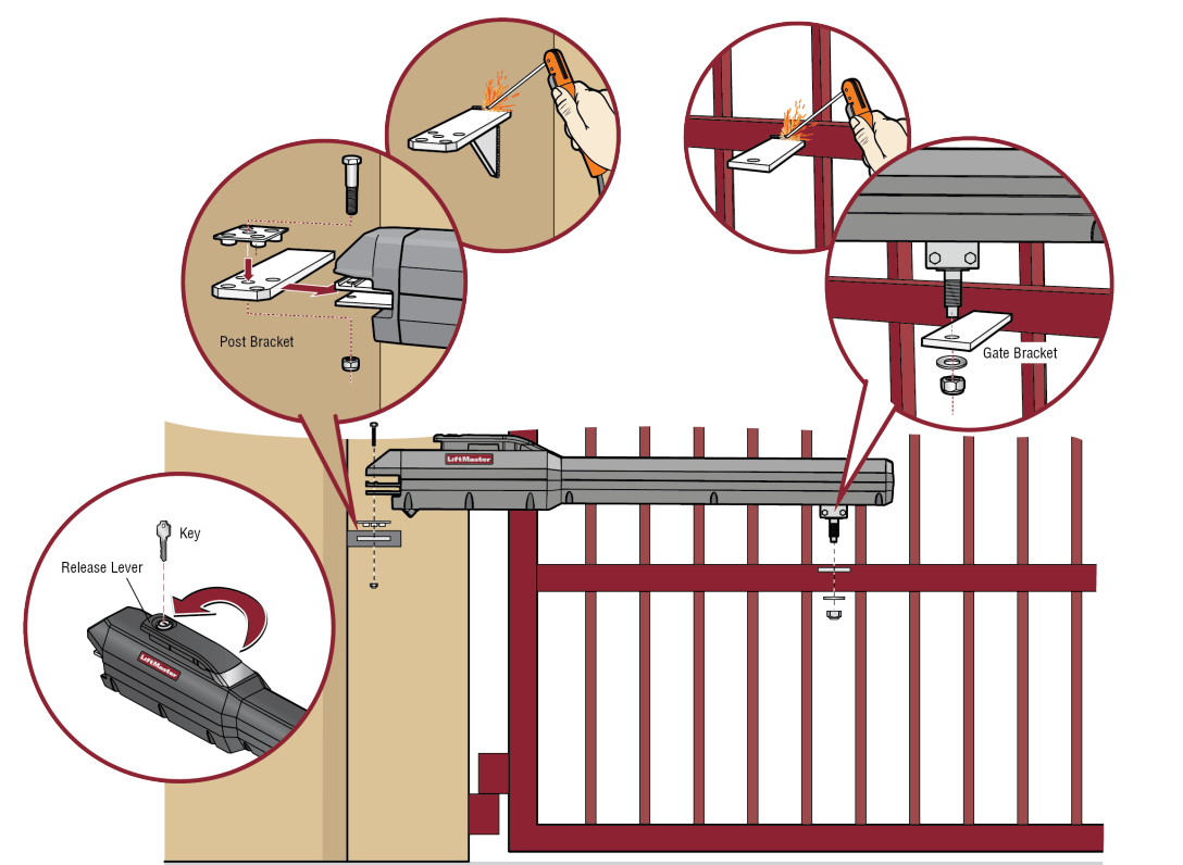
Step 2 Attach the Brackets
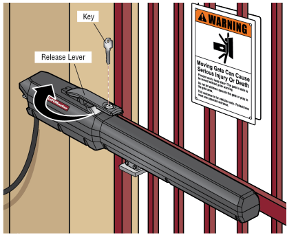
1. Insert the key into the lock and turn it 180 degrees counterclockwise. Turn the release lever 180 degrees counterclockwise. The operator is now in manual mode.
2. Position the operator on the brackets and make sure the operator is level and positioned correctly on the gate.
3. Remove the operator from the gate.
4. Completely weld around the post bracket and gate bracket.
NOTE: Brackets may need additional reinforcement by welding flat stock as shown.
5. Attach the operator to the post bracket with the bolt, mounting plate, and nut as shown.
6. Attach gate bracket to operator with the bolt, washer, and nut as shown. Tighten the nut until it reaches the bottom of the gate bracket, then turn the nut a half turn, making sure not to overtighten. Make sure the trolley does not reach the fully open or fully closed position. NOTE: Extra force may be needed to move the trolley back and forth.
For dual gate applications, repeat the previous installation steps to install the second operator.
Step 3 Install the Control Box
Standard Control Box
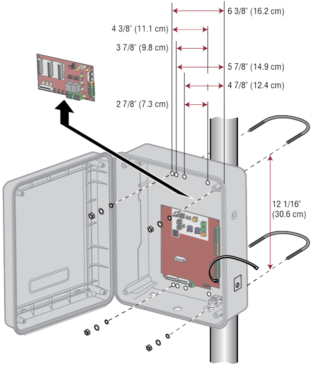
The control box MUST be mounted within 5 feet (1.52 m) of the gate operator. Mount the control box as high as possible for best radio reception. Make sure the control box is level.
NOTE: The expansion board DOES NOT need to be removed for a wall or column mount installation.
1. Remove the screws and open the control box.
2. Disconnect the "Main Board" connector from the expansion board.
3. Remove the expansion board by removing the screws.
4. Select the mounting holes (according to your application) and remove the knockouts using a screwdriver and hammer.
5. Secure the control box to mounting surface.
A. Wall or Column: Use the provided screws (4).
B. Post: Use U-bolts and rubber washers (not provided) to ensure a watertight seal. Make sure the U-bolts do not protrude more than 3/4 inch from the control box because this can short the control board.
6. Reinstall the expansion board and connect the "Main Board" connector to the expansion board.
Large Metal Control Box
The control box MUST be mounted within 5 feet (1.52 m) of the gate operator. Mount the control box as high as possible for best radio reception. Make sure the control box is level.
NOTE: The Large Metal Solar Control Box (Model XLSOLARCONTUL) does not have the electrical outlets or the expansion board shown in the images.
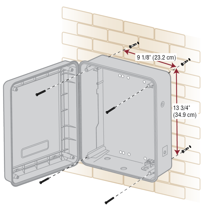
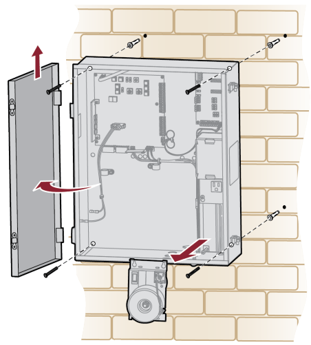
Wall or Column Mount
1. Open the control box. The control box door may be removed by opening the door 90°. Lift the door from the hinges and set aside until the installation is complete.
2. Remove the toroid assembly from the control box by loosening the three screws and lifting the assembly up and out.
3. Use knock outs located at the 4 corners of the control box and knock out using a screwdriver and hammer.
4. Secure the control box to mounting surface using the provided screws (4).
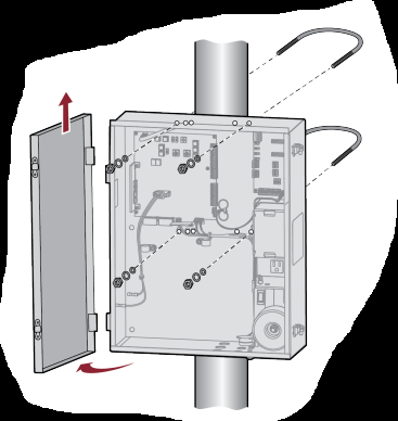
Post Mount
NOTE: The post mount option is not recommended for the 33AH battery application.
1. Open the control box. The control box door may be removed by opening the door 90°. Lift the door from the hinges and set aside until the installation is complete.
2. The control box can be mounted to a post with 'U' bolts (refer to chart). The knock out will accommodate a 3/8" diameter 'U' bolt. Select center mounting holes (top and bottom) and knock out using a screwdriver and hammer.
3. Secure the control box to mounting surface with U-bolts and rubber washers (not provided) to ensure a watertight seal.
WARNING
● ANY maintenance to the operator or in the area near the operator MUST NOT be performed until disconnecting the electrical power (AC or solar and battery) and locking-out the power via the operator power switch. Upon completion of maintenance the area MUST be cleared and secured, at that time the unit may be returned to service.
● Disconnect power at the fuse box BEFORE proceeding. Operator MUST be properly grounded and connected in accordance with national and local electrical codes. NOTE: The operator should be on a separate fused line of adequate capacity.
● ALL electrical connections MUST be made by a qualified individual.
● DO NOT install ANY wiring or attempt to run the operator without consulting the wiring diagram.
● ALL power wiring should be on a dedicated circuit and well protected. The location of the power disconnect should be visible and clearly labeled.
● ALL power and control wiring MUST be run in separate conduit.
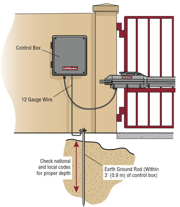
Step 4 Earth Ground Rod
Use the proper earth ground rod for your local area. The ground wire must be a single, whole piece of wire. Never splice two wires for the ground wire. If you should cut the ground wire too short, break it, or destroy its integrity, replace it with a single wire length.
1. Install the earth ground rod within 3 feet (.9 m) of the operator.
2. Run wire from the earth ground rod to the control box.
NOTE: If the operator is not grounded properly the range of the remote controls will be reduced and the operator will be more susceptible to lightning and surge damage.
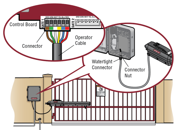
Step 5 Wire the Operator Arm to the Control Board
1. Choose a knockout in the bottom of the control box.
2. Insert the operator cable through the provided watertight connector. 3. Insert the operator cable and watertight connector into the knockout. 4. Slide the connector nut onto the operator cable.
5. Connect the operator cable wires to the connector according to the colored label on the connector (white to white, red to red, etc.).
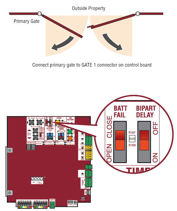
6. Plug the connector into the GATE 1 terminal on the control board as shown.
7. Tighten the connector nut.
If installing two operators, go to the following page.
Step 6 Dual Gate Setup
There are two options for dual gate communication: wired or wireless. Follow the directions according to your application. Do not use wired and wireless communication simultaneously. Wired dual gate applications will have a longer battery standby time than wireless applications. Wireless dual gates will require the installation of two control boxes, one for each operator arm.
1. Wireless Setup Install a second operator arm and control box:
1. Choose an operator to be the network primary operator. All wireless accessories will need to be programmed to the primary operator. NOTE: We recommend that all accessories and board configurations are set on the primary operator.
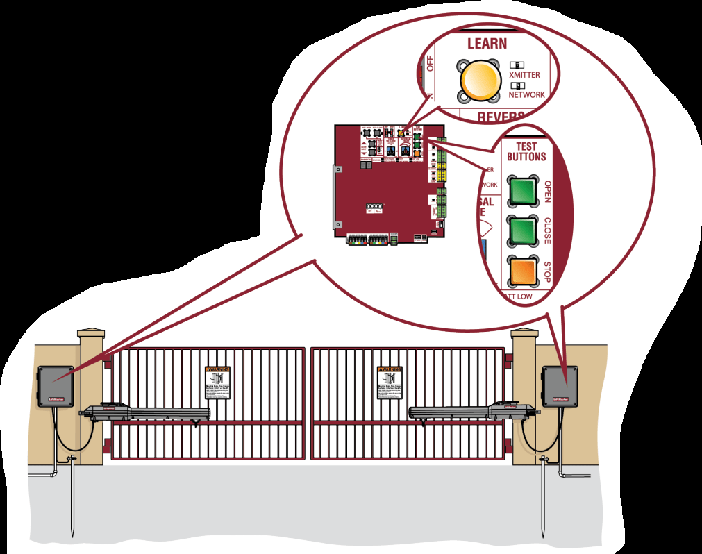
2. Press and release the LEARN button on the primary operator. The green XMITTER LED will light. NOTE: The operator will time out of programming mode after 180 seconds.
3. Press and release the LEARN button again on the primary operator. The yellow NETWORK LED will light.
4. Press and release the OPEN test button to assign this operator as network primary.
5. Press and release the LEARN button on the second operator. The green XMITTER LED will light.
6. Press and release the LEARN button again on the second operator. The yellow NETWORK LED will light.
7. Press and release the CLOSE test button to assign this operator as network second.
Both operators will beep and the yellow NETWORK LEDs will turn off indicating programming is successful.
2. To deactivate the wireless feature:
1. Press and release the LEARN button on either operator. The green XMITTER LED will light.
2. Press and release the LEARN button again on the same operator. The yellow NETWORK LED will light.
3. Press and hold the LEARN button for 5 seconds. The yellow NETWORK LED will blink (operator will beep) then turn off indicating successful deactivation.
4. Repeat the steps for the other operator.
3. Wired Setup
Install a second operator arm by following installation steps 1-2.
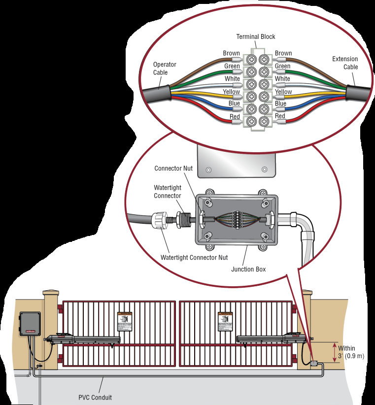
Install the extension cable and junction box:
Before digging, contact local underground utility locating companies.
1. Trench across driveway to bury the extension cable. Use PVC conduit to prevent damage to cables.
2. Open the junction box by removing screws (4) and set aside.
3. Select holes to be used for mounting and knock out using a screwdriver and hammer. Drill two holes in the junction box large enough for the watertight connectors.
4. Mount the junction box within 3 feet (0.9 m) of second operator.
5. Route operator cable and extension cable through watertight connector nut and watertight connector.
6. Insert the cables and watertight connectors into the holes in the junction box.
7. Slide the connector nut onto the operator cable and extension cable.
8. Connect the wires from extension cable and operator cable to the terminal block connector as shown (like-colored wires must face each other).
9. Put wires inside of junction box.
10. Secure operator and extension cables by tightening the connector nut.
11. Reinstall cover.
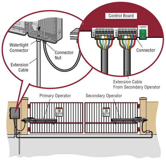
4.Wire the secondary operator arm to the control board:
1. Choose a knockout in the bottom of the control box.
2. Insert the extension cable through the watertight connector.
3. Insert the extension cable and watertight connector into the knockout.
4. Slide the connector nut onto the operator cable.
5. Connect the extension cable wires to the connector according to the colored label on the connector (white to white, red to red, etc.).
6. Plug the connector into the GATE 2 terminal on the control board as shown.
7. Tighten the connector nut.
5. Set the bipart delay (single control box):
Occasionally in dual gate installations, one gate will need to open first and close second. This would happen if there was an ornamental overhang on one gate or if using a solenoid lock, for example. This gate is called the Primary gate and needs to be connected to Gate 1 connections on the control board. Thus, it is preferred that the control box be installed on the same side as this gate. If there is no appropriate location on that side for the control box, then mount the control box on the opposite side, but connect the operator closest to the control box to the Gate 2 connector and the operator on the opposite side to the Gate 1 connector.
1. The BIPART DELAY switch on the control board needs to be set to the ON position.
The illustration shows a dual gate configuration with a decorative overlapping piece on the outside of the gate.
Set the bipart delay (dual control box)
The BIPART DELAY switch is used with dual control box applications and serves two functions:
● BIPART DELAY: The BIPART DELAY is used in applications where a mag-lock, solenoid lock, or decorative overlay would require one gate to close before the other. The control box with the BIPART DELAY switch ON will delay from the close limit when opening and be the first to close from the open limit.
● SYNCHRONIZED CLOSE: The BIPART DELAY is also used in applications where one gate travels a longer distance than the other. To synchronize the closing of the gates, set the BIPART DELAY switch to ON for both control boxes.
WARNING To prevent SERIOUS INJURY or DEATH from a moving gate:
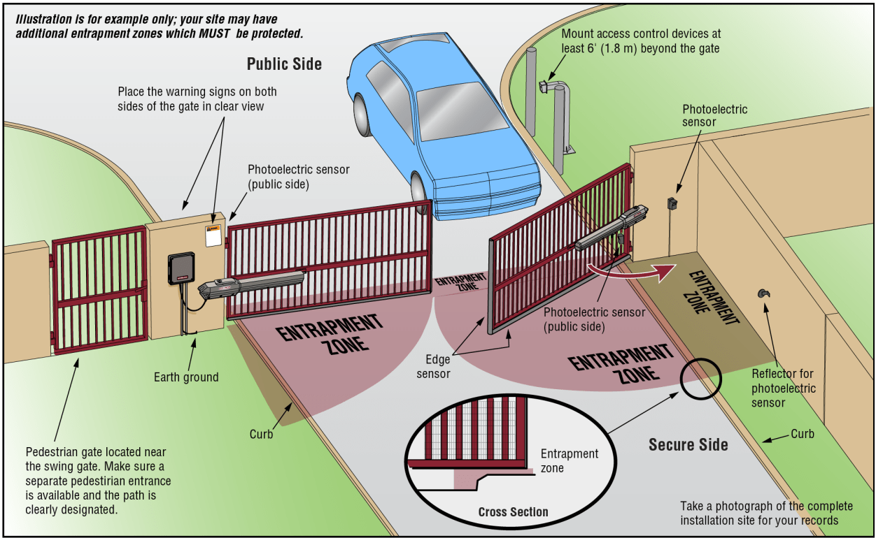
● ALL gate operator systems REQUIRE two independent entrapment protection systems for each entrapment zone.
● Entrapment protection devices MUST be installed to protect anyone who may come near a moving gate. the manual provided with your entrapment protection device.
● Locate entrapment protection devices to protect in BOTH the open and close gate cycles.
● Locate entrapment protection devices to protect between moving gate and RIGID objects, such as posts, walls, pillars, columns, or operator itself.
Step 7 Install Entrapment Protection
Entrapment protection MUST be installed according to the following UL 325 requirements:
● Swing gate operators require the installation of the first external monitored entrapment protection device to function.
● Every installation is unique. It is the responsibility of the installer to ensure that ALL entrapment zones are protected with an external monitored entrapment protection device, protecting both the open and close gate cycles.
● LiftMaster monitored external entrapment protection devices MUST be used with LiftMaster operators to meet UL325 requirements, see Accessories.
● Test ALL entrapment protection devices after completing installation of the operator. For testing instructions, refer to the manual provided with your entrapment protection device.
● Locate entrapment protection devices to protect in BOTH the open and close gate cycles.
● Locate entrapment protection devices to protect between moving gate and RIGID objects, such as posts, walls, pillars, columns, or operator itself.
Definitions
ENTRAPMENT: The condition when a person is caught or held in a position that increases the risk of injury.
SWING GATE ENTRAPMENT ZONE: Locations between a moving gate or moving, exposed operator components and a counter opposing edge or surface where entrapment is possible up to 1.8 m (6 ft) above grade. Such locations occur if during any point in travel:
a. The gap between the bottom of a moving gate and the ground is greater than 101.6 mm (4 in) and less than 406 mm (16 in); or
b. The distance between the center line of the pivot and the end of the wall, pillar, or column to which it is mounted when in the open or closed position exceeds 101.6 mm (4 in). Any other gap between a moving gate and fixed counter opposing edges or surfaces or other fixed objects is less than 406 mm (16 in) (examples are walls, curbs, berms or other immovable objects).
Illustrations provided by DASMA Gate Systems Safety Guide
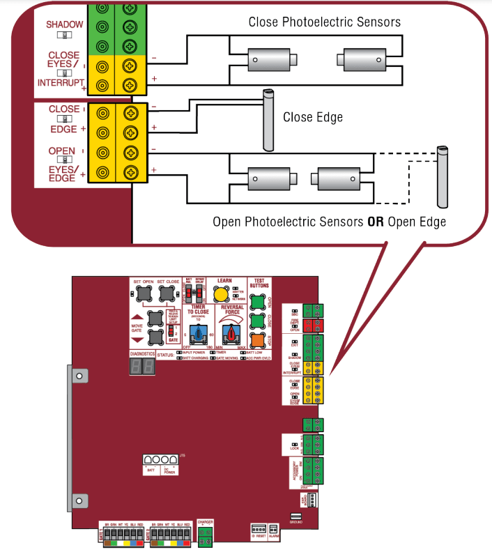
Wire Entrapment Protection Devices
There are three options for wiring the entrapment protection devices depending on the specific device and how the device will function. Refer to the specific entrapment protection device manual for more information. These entrapment protection device inputs are for monitored devices, which include pulsed photoelectric sensors, resistive edge sensors, and pulsed edge sensors. Only one monitored entrapment protection device may be wired to each input. Additional entrapment protection devices may be wired to the expansion board.
Control Board
CLOSES EYES/INTERRUPT
(2 Terminals) The CLOSE EYES/INTERRUPT input is for photoelectric sensor entrapment protection for the close direction. When an obstruction is sensed during gate closing the gate will open to the full open position and resets the Timer-to-Close. This input will be disregarded during gate opening.
CLOSE EDGE
(2 Terminals) The CLOSE EDGE input is for edge sensor entrapment protection for the close direction. When an obstruction is sensed during gate closing the gate will reverse to the full open position, disengaging the Timer-to-Close. This input will be disregarded during gate opening.
OPEN EYES/EDGE
(2 Terminals) The OPEN EYES/EDGE input is for photoelectric sensor or edge sensor entrapment protection for the open direction. When an obstruction is sensed during gate opening the gate will reverse for 4 seconds then stop. This input will be disregarded during gate closing.
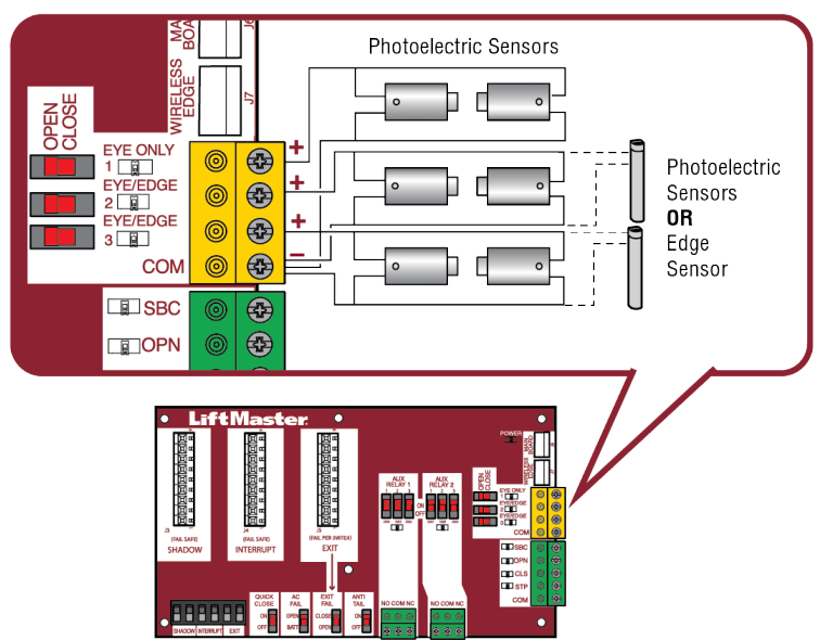
EYE ONLY and COM
Open or Close Direction Photoelectric Sensors, the functionality is based on the switch settings (located next to the terminals)
Switch set to CLOSE: gate reverses fully when an obstruction is sensed
Switch set to OPEN: gate reverses 4 seconds when an obstruction is sensed
EYE/EDGE and COM
Open or Close Direction Photoelectric Sensors or Edge Sensor, the functionality is based on the switch settings (located next to the terminals)
Switch set to CLOSE: gate reverses fully when an obstruction is sensed
Switch set to OPEN: gate reverses 4 seconds when an obstruction is sensed
Step 8 Power Wiring
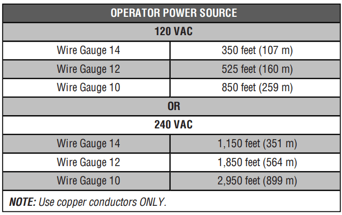
The standard control box can be wired for either 120 Vac or 240 Vac. Factory default is 120 Vac. The Large Metal Control Box (XLM) can be wired for 120 Vac (default). The batteries are charged in the circuit by the toroid transformer, plug-in transformer, or the solar panels. Main power supply and control wiring MUST be run in separate conduits. SOLAR APPLICATIONS: For solar applications refer to Solar Panels section in the Appendix. Follow the directions according to your application.
NOTE: If using an external receiver use shielded wire for the connections and mount the receiver away from the operator to avoid interference from the operator.
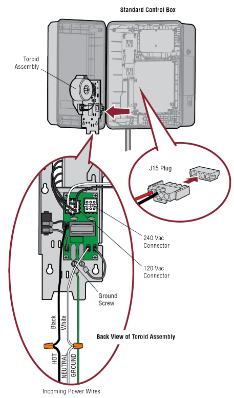
Standard Control Box
1. Turn off the AC power from the main power source circuit breaker.
2. Run the AC power wires to the control box.
3. Remove the toroid assembly from the control box by loosening the four screws and lifting the assembly up and out.
4. Ensure the 120/240 plug is connected to either the 120 or 240 Vac connector on the EMI board depending on your application. Factory default is 120 Vac.
5. Connect the ground wire to the ground screw on the back of the toroid assembly.
6. Connect the white wire from the toroid assembly to NEUTRAL using a wire nut.
7. Connect the black wire from the toroid assembly to HOT using a wire nut.
8. Replace the toroid assembly and tighten the four screws. Ensure the wires are not pinched.
9. Plug the J15 plug into the control board. The control board will power up. NOTE: You may see a small spark when plugging the J15 plug into the board.
10. Turn ON AC power to the operator.
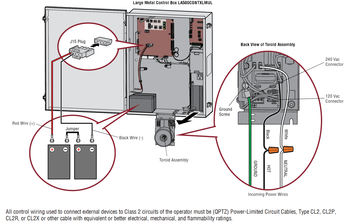
Large Metal Control Box
To use solar panels with the Large Metal Control Box (Model XLSOLARCONTUL) skip the steps below and refer to the Solar Panels section in the Appendix.
1. Unplug the J15 plug labeled BATT(-)(+) DC(-)(+) on the control board by squeezing the plug and pulling it from the control board.
2. Turn off the AC power from the main power source circuit breaker.
3. Run the AC power wires to the control box.
4. Remove the toroid assembly from the control box by loosening the three screws and lifting the assembly up and out.
5. Ensure the 120/240 plug is connected to either the 120 or 240 Vac connector on the EMI board depending on your application. Factory default is 120 Vac.
6. Connect the ground wire to the ground screw on the back of the toroid assembly.
7. Connect the white wire from the toroid assembly to NEUTRAL using a wire nut.
8. Connect the black wire from the toroid assembly to HOT using a wire nut.
9. Replace the toroid assembly and tighten the screws. Ensure the wires are not pinched.
10. Connect a jumper between the positive (+) terminal of one battery to the negative (-) terminal of the other battery. 11. Connect the red wire from the J15 plug labeled BATT (+) to the positive (+) terminal of the battery.
12. Connect the black wire from the J15 plug labeled BATT (-) to the negative (-) terminal of the battery.
13. Plug the J15 plug into the control board. The control board will power up. NOTE: You may see a small spark when plugging the J15 plug into the board.
14. Turn ON AC power.
Step 9 Finish Installation
1. Turn the release lever clockwise 180° back to the engaged position. This engages the motor. The illustration shows the release lever in the engaged position.
2. Turn the key clockwise 180°. This locks the release lever. The operator is now engaged.
3. Fasten warning signs to the gate with cable ties. Warning signs MUST be installed on both sides of the gate and in plain view.
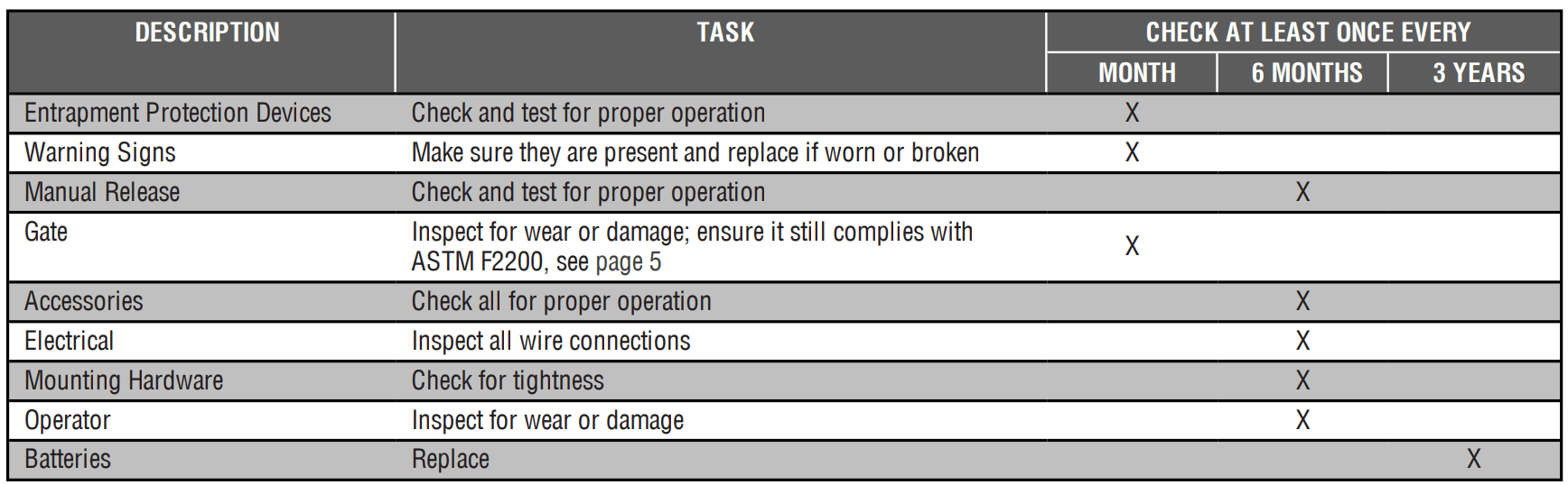
MAINTENANCE
Maintenance Chart
TROUBLESHOOTING
Code
Meaning
Solution
Saved
LIFTMASTER SYSTEM
31
Main control board has experienced an internal failure.
Disconnect all power, wait 15 seconds, then reconnect power (reboot). If issue continues, replace main control board.
NO
32
Linear Drive Disengaged (Arm 1)
Disengage then re-engage arm. Check wiring and connections.
YES
33
Linear Drive Disengaged (Arm 2)
35
Max-Run-Time Exceeded Error
Check for an obstruction, then reprogram the limits.
YES
36
Product ID Error
Was the control board just replaced? If so, erase limits, enter limit setup mode and set limits. If not, disconnect all power, wait 15 seconds, then reconnect power before changing product ID harness.
YES
37
Product ID Failure
Unplug product ID harness then plug back in. Disconnect all power, wait 15 seconds, then reconnect power before replacing product ID harness.
YES
38
Hard Stop Limit (Arm 1)
Limit may be set too tightly against a non-resilient hard stop (re-adjust
NO
39
Hard Stop Limit (Arm 2)
limit). Operator may be at end of travel (re-adjust mounting).
40
Battery overvoltage
Too much voltage on the battery. Check harness. Make sure there is NOT a 24V battery on a 12V system.
YES
41
Battery overcurrent
Possible short of the battery charge harness. Check harness. Make sure you do NOT have a 12V battery on a 24V system.
YES
42
No battery at boot up
Check battery connections and installation. Replace batteries if depleted to less than 20V on a 24V system or less than 10V on a 12V system. Make sure there is NOT a single 12V battery on a 24V system.
YES
INSTALLED SYSTEM
43
Exit Loop Error
Failure or missing loop (SHORT or OPEN - LiftMaster Plug-in Loop
YES
44
Shadow Loop Error
Detector only) Check loop wiring throughout connection. May be a short in the loop, or an open connection in the loop.
45
Interrupt Loop Error
46
Wireless edge battery low
Replace batteries in wireless edge.
YES
INFORMATIONAL
51
Pass-point not detected (Arm 1)
Checkyellow pass-point wiring. If limits are not accurate, reprogram.
NO
52
Pass-point not detected (Arm 2)
53
Brownout occurred
AC/DC board supply dipped below allowable level. Review power supply and wiring. If rebooting, ensure enough time for discharge of power to force a fresh boot.
YES
54
Wireless Second Operator Communication Error
Check the second operator for power. If OFF, restore power and try to run the system. If powered, deactivate the wireless feature and then re-learn the second operator.
YES
EXTERNAL ENTRAPMENT PROTECTION
60
Minimum number of monitored entrapment protection devices not installed.
Review monitored entrapment protection device connections. This swing gate operator will operate only after installation of a minimum of one external safety device in either the open or close direction.
NO
61
CLOSE EYE/INTERRUPT held more than 3 minutes
Check wired input on main control board; check for alignment or obstruction.
YES
62
CLOSE EDGE held more than 3 minutes
63
OPEN EYE/EDGE held more than 3 minutes
64
CLOSE EYE/INTERRUPT held more than 3 minutes
Check wired input on expansion board; check for alignment or obstruction.
YES
65
CLOSE EYE/EDGE held more than 3 minutes
66
OPEN EYE/EDGE held more than 3 minutes
67
Wireless edge triggered more than 3 minutes
Check wired input for wiring issue or obstruction.
YES
68
Wireless edge loss of monitoring
Check wireless edge inputs.
YES
69
Wireless edge triggered
IF an obstruction occurred, no action required. If an obstruction did NOT occur, check inputs and wiring.
NO
70
CLOSE EYE/INTERRUPT triggered, causing reversal, preventing close, or resetting TTC
IF an obstruction occurred, no action required. If an obstruction did NOT occur, check alignment, inputs, and wiring on main control board
NO
71
CLOSE EDGE triggered, causing reversal, NO preventing close, or canceling TTC
72
OPEN EYE/EDGE triggered, causing reversal or preventing opening
73
CLOSE EYE/INTERRUPT triggered, causing reversal, preventing close, or resetting TTC
IF an obstruction occurred, no action required. If an obstruction did NOT occur, check alignment, inputs, and wiring on expansion board.
NO
74
CLOSE EYE/EDGE triggered, causing reversal and preventing close or canceling TTC
75
OPEN EYE/EDGE triggered, causing reversal or preventing opening
80
Close input (EYE/EDGE) communication fault from other operator
Check inputs and communication method between operators, either wired bus or radio. Ensure operator is powered. May have to erase the wireless communication and reprogram the two operators.
YES
81
Open input (EYE/EDGE) communication fault from other operator
82
Close input (EYE/EDGE) communication fault (expansion board)
Checkthe connections between the main board and the expansion board.
YES
83
Open input (EYE/EDGE) communication fault (expansion board)
84
Non-monitored device detected on the wireless safety system
Non-monitored contact closure devices are not supported. Make sure connected devices are monitored. Check edges for proper orientation and resistive end cap connection.
YES
INHERENT ENTRAPMENT PROTECTION
91
Force Reversal (Operator 1)
Check for obstruction. If no obstruction, check that the mechanical assembly is engaged and free to move. See section on Limit and Force Adjustment, and Obstruction Test.
YES
92
Force Reversal (Operator 2)
93
RPM/STALL Reversal (Operator 1)
Check for obstruction. If no obstruction, checkthe operator wiring and that the mechanical assembly is engaged and free to move. Replace APE assembly.
YES
94
RPM/STALL Reversal (Operator 2)
99
Normal Operation
No action required
YES
Control Board LEDs
STATUS LEDS
INPUT
POWER
OFF
OFF state
ON
AC charger or Solar power available
BATT
CHARGING
OFF
Not charging
ON
Three stage battery charging
TIMER
OFF
The timer is disabled
ON
The timer is enabled
MEDIUM BLINK (1 blink per second)
The timer is running
FAST BLINK (2 blinks per second)
The timer is paused
FASTEST BLINK (8 blinks per second)
The timer is canceled
GATE MOVING
OFF
The gate is stopped
ON
The gate is opening or closing
MEDIUM BLINK (1 blink per second)
Operator is in E1 (single entrapment)
FASTEST BLINK (8 blinks per second)
The operator is in E2 (double entrapment)
BATT LOW
OFF
No battery error
ON
Battery low
MEDIUM BLINK (1 blink per second)
Battery critically low
ACC PWR OVLD
OFF
OFF state
ON
Accessory overload protector opened
INPUT LEDS
SBC INPUT
OFF
Input inactive
ON
Input active
BLINK
Input active on other operator
FIRE DEPT INPUT
OFF
Input inactive
ON
Input active
BLINK
Input active on other operator
EXIT
OFF
Input inactive
ON
Input active
BLINK
Input active on other operator
SHADOW
OFF
Input inactive
ON
Input active
BLINK
Input active on other operator
CLOSE
EYES/INTERRUPT
OFF
Input inactive
ON
Input active
BLINK
Input active on other operator
CLOSE EDGE
OFF
Input inactive
ON
Input active
BLINK
Input active on other operator
OPEN EYES/EDGE
OFF
Input inactive
ON
Input active
BLINK
Input active on other operator
LOCK
OFF
Maglock relay inactive
ON
Maglock relay active
SYMPTOM
POSSIBLE CAUSES
SOLUTIONS
Operator does not run and diagnostic display not on.
a. No power to control board
b. Open fuse
c. If on battery power only, low or dead batteries
d. Defective control board
a. Check AC and battery power
b. Check fuses
c. Charge batteries by AC or solar power or replace batteries
d. Replace defective control board
Control board powers up, but motor does not run.
a. Reset switch is stuck
b. Stop button active or jumper not in place for stop circuit
c. If on battery power only, low or dead batteries
d. Open or Close input active
e. Entrapment Protection Device active
f. Vehicle loop detector or probe active
g. Defective control board
a. Check reset switch
b. Check Stop button is not “stuck on”, or verify that the stop button is a normally closed circuit, or put a jumper on the stop circuit.
c. Charges batteries by AC or solar power or replace batteries
d. Check all Open and Close inputs for a “stuck on” input
e. Check all Entrapment Protection Device inputs for a “stuck on” sensor
f. Check all vehicle detector inputs for a “stuck on” detector
g. Replace defective control board
Arm moves, but cannot set correct limits.
a. Arm does not extend or retract enough during travel
b. Arm is interfering with mounting bracket
c. Gate is too difficult to move
a. Disengage the arm and ensure arm moves freely
b. Examine the hinge point where the arm mounts to the gate post. Make sure that the arm housing does not hit or interfere with the gate post or mounting bracket. Correct as necessary.
c. Disconnect arm from gate and move gate manually. Gate must move easily and freely through its entire range, limit-to-limit. Repair gate as needed.
Gate does not fully open or fully close when setting limits.
a. Arm does not extend or retract enough during travel
b. Arm is interfering with mounting bracket
c. Gate is too difficult to move
a. Disengage the arm and ensure arm moves freely
b. Examine the hinge point where the arm mounts to the gate post. Make sure that the arm housing does not hit or interfere with the gate post or mounting bracket. Correct as necessary.
c. Remove arm from gate and move gate manually. Gate must move easily and freely through its entire range, limit-to-limit. Repair gate as needed.
Operator does not respond to a wired control/command (example: Open, Close, SBC, etc.)
a. Check Open and Close command input LEDs
b. Stop button is active
c. Reset button is stuck
d. If on battery power only, low or dead batteries
e. Entrapment Protection Device active
f. Vehicle loop detector or vehicle probe active
a. Check all Open and Close inputs for a “stuck on” input
b. Check Stop button is not “stuck on”
c. Check Reset button
d. Charges batteries by AC or solar power or replace batteries
e. Check all Entrapment Protection Device inputs for a “stuck on” sensor
f. Check all vehicle detector inputs for a “stuck on” detector
Operator does not respond to a wireless control or transmitter
a. CheckXMITTER LED when wireless control is active
b. Stop button is active
c. Reset button is stuck
d. Poor radio reception
a. Activate wireless control and check XMITTER LED is on. Re-learn wireless control/transmitter to control board. Replace wireless control as needed.
b. Check Stop button is not “stuck on”
c. Check Reset button
d. Check if similar wired control operates correctly. Check if wireless controls works properly when within a few feet of operator. Check operator's antenna and antenna wire. Check other wireless controls or devices.
Gate stops during travel and reverses immediately.
a. Control (Open, Close) becoming active
b. Vehicle loop detector active
c. Low battery voltage
a. Check all Open and Close inputs for an active input
b. Check all vehicle detector inputs for an active detector
c. Battery voltage must be 23.0 Vdc or higher. Charge batteries by AC or solar power or replace batteries
SYMPTOM
POSSIBLE CAUSES
SOLUTIONS
Gate opens, but will not close with transmitter or Timer-to-Close.
a. Open control active
b. Vehicle loop detector active
c. Fire Dept input active
d. Timer-to-Close not set
e. Close Entrapment Protection Device active
a. Check all Open inputs for an active input
b. Check all vehicle detector inputs for an active detector
c. Check AC power and AC Fail option setting
d. Check if AC power is available. If no AC power, then running on batteries and battery voltage must be 23.0 Vdc or higher. Charge batteries by AC or solar power or replace batteries.
e. Check Fire Dept input
f. Check Timer-to-Close (TTC) setting
g. Check all Entrapment Protection Device inputs for an active sensor
Gate closes, but will not open.
a. Vehicle loop detector active
b. Low battery with LOW BATT option set to CLOSE
a. Check all vehicle detector inputs for an active detector
b. Check if AC power is available. If no AC power, then running on batteries and battery voltage must be 23.0 Vdc or higher. Charge batteries by AC or solar power or replace batteries.
Exit loop activation does not cause gate to open.
a. Exit vehicle detector setup incorrectly
b. Defective Exit loop detector
c. Low battery with LOW BATT option set to CLOSE
a. Review Exit loop detector settings. Adjust settings as needed.
b. Replace defective Exit loop detector.
c. Check if AC power is available. If no AC power, then running on batteries and battery voltage must be 23.0 Vdc or higher. Charge batteries by AC or solar power or replace batteries.
Interrupt loop does not cause gate to stop and reverse.
a. Vehicle detector setup incorrectly
b. Defective vehicle loop detector
a. Review Interrupt loop detector settings. Adjust settings as needed.
b. Replace defective Interrupt loop detector.
Shadow loop does not keep gate at open limit.
a. Vehicle detector setup incorrectly
b. Defective vehicle loop detector
a. Review Shadow loop detector settings. Adjust settings as needed.
b. Replace defective Shadow loop detector.
Obstruction in gate's path does not cause gate to stop and reverse.
a. Force adjustment needed
a. Refer to the Adjustment section to conduct the obstruction test and perform the proper force adjustment that is needed.
Photoelectric sensor does not stop or reverse gate.
a. Incorrect photoelectric sensor wiring
b. Defective photoelectric sensor
a. Check photoelectric sensor wiring. Retest that obstructing photoelectric sensor causes moving gate to stop, and may reverse direction.
b. Replace defective photoelectric sensor. Retest that obstructing photoelectric sensor causes moving gate to stop, and may reverse direction.
Edge Sensor does not stop or reverse gate.
a. Incorrect edge sensor wiring
b. Defective edge sensor
a. Check edge sensor wiring. Retest that activating edge sensor causes moving gate to stop and reverse direction.
b. Replace defective edge sensor. Retest that activating edge sensor causes moving gate to stop and reverse direction.
Alarm sounds for 5 minutes or alarm sounds with a command.
a. Double entrapment occurred (two obstructions within a single activation)
a. Check for cause of entrapment (obstruction) detection and correct. Press the reset button to shut off alarm and reset the operator.
Alarm beeps three times with a command.
a. Low battery
a. Check if AC power is available. If no AC power, then running on batteries and battery voltage must be 23.0 Vdc or higher. Charge batteries by AC or solar power or replace batteries
On dual-gate system, incorrect gate opens first or closes first.
a. Incorrect Bipart switch setting
a. Change setting of both operator's Bipart switch settings. One operator should have Bipart switch ON (operator that opens second) and the other operator should have Bipart switch OFF (operator that opens first).
Alarm beeps when running.
a. Expansion board setting
b. Constant pressure to open or close is given
a. Pre-warning is set to "ON"
b. Constant pressure to open or closed is given
SYMPTOM
POSSIBLE CAUSES
SOLUTIONS
Expansion board function not controlling gate.
a. Defective main board to expansionboard wiring
b. Incorrect input wiring to expansion board
c. Defective expansion board or defective main board
a. Check main board to expansion board wiring. If required, replace wire cable.
b. Check wiring to all inputs on expansion board.
c. Replace defective expansion board or defective main board
Maglocknot working correctly.
a. Maglock wired incorrectly
a. Check that Maglock is wired to N.C. and COM terminals. Check that Maglock has power (do not power maglock from control board accessory power terminals). If shorting lock's NO and COM wires does not activate Maglock, then replace Maglock or Maglock wiring (refer to Wiring Diagrams).
Solenoid lock not working correctly.
a. Solenoid wired incorrectly
a. Check that Solenoid is wired to N.O. and COM terminals. Check that Solenoid has power (do not power solenoid from control board accessory power terminals). If shorting lock's NC and COM wires does not activate Solenoid, then replace Solenoid lock or Solenoid wiring (refer to Wiring Diagrams).
Switched (SW) Accessory power remaining on.
a. In limit setup mode
a. Learn the limits
Accessories connected to Switch (SW) Accessory power not working correctly, turning off, or resetting.
a. Normal behavior
a. Move accessory to accessory power "ON"
Accessories connected to Accessory power not working correctly, turning off, or resetting.
a. Accessory power protector active
b. Defective control board
a. Disconnect all accessory powered devices and measure accessory power voltage (should be 23-30Vdc). If voltage is correct, connect accessories one at a time, measuring accessory voltage after every new connection.
b. Replace defective control board
Quick Close not working correctly.
a. Quick Close setting incorrect
b. Interrupt loop detector
c. Defective Expansion board
a. Checkthat Quick Close setting is ON
b. Check operation of Interrupt Loop detector
c. Replace defective Expansion board
Anti-Tailgating not working correctly.
a. Anti-Tail setting incorrect
b. Interrupt loop detector
c. Defective Expansion board
a. Checkthat Anti-Tail setting is ON
b. Check operation of Interrupt Loop detector
c. Replace defective Expansion board
AUX Relay not working correctly.
a. AUX Relay setting incorrect
b. AUX Relay wiring incorrect
c. Defective Expansion board
a. Check AUX Relay switches settings
b. Checkthat wiring is connected to either N.O. and COM or to N.C. and COM.
c. Set AUX Relay to another setting and test. Replace defective expansion board.
Solar operator not getting enough cycles per day.
a. Insufficient panel wattage
b. Excessive accessory power draw
c. Old batteries
d. Solar panels are not getting enough sunlight
a. Add more solar panels
b. Reduce the accessory power draw by using LiftMaster low power accessories
c. Replace batteries
d. Relocate the solar panels away from obstructions (trees, buildings, etc.)
Solar operator, insufficient standby time.
a. Insufficient panel wattage
b. Excessive accessory power draw
c. Battery capacity too low
a. Add more solar panels
b. Reduce the accessory power draw by using LiftMaster low power accessories
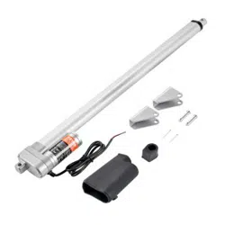
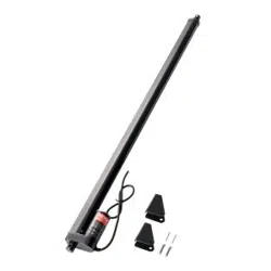
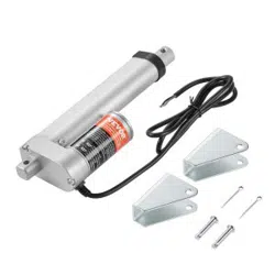
#1 I am looking for dual gate motors. Is this for two arms or one? How quiet are these?
This is for a dual swing gate application and includes two linear actuator motor arms. They are quiet.
#2 What one is the light commercial dual actuator 110v
This one shown in the picture. I have two 10ft gates and this moves it rapid. The battery back up gives u a worry free of ever not be able to open or close gate while power outage