1
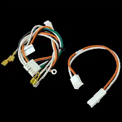
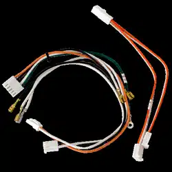
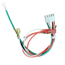
Replacement Wire Harness Instructions
Model 041D9204
To prevent possible SERIOUS INJURY or
DEATH:
• Disconnect ALL electric and battery
power BEFORE performing ANY
service or maintenance.
Before you begin
1. Disconnect both electrical and battery
power (if applicable) to the garage door
opener.
2. Remove the LED light pods.
a. Pull the top sides of the light lens and
rotate the light lens down.
b. Unplug the LED light pod by
squeezing the connector.
c. Squeeze the light lens clips to remove
the lens from the end panel.
3. Remove the 8 screws to the chassis
cover and remove it.
4. Disconnect the wires on the wire
terminal.
5. Remove screws from end panel.
6. Unplug the wire harness from the logic
board and end panel.
7. Unplug the ORANGE AND WHITE wires
from the LED Driver board.
• To prevent damage to the receiver
logic board, DO NOT touch printed
circuit board of replacement receiver
logic board during installation.
• ALWAYS wear protective gloves and
eye protection when changing the
battery or working around the battery
compartment.
WARNING: This product can
expose you to chemicals including
lead, which are known to the State
of California to cause cancer or
birth defects or other reproductive
harm. For more information go to
www.P65Warnings.ca.gov.
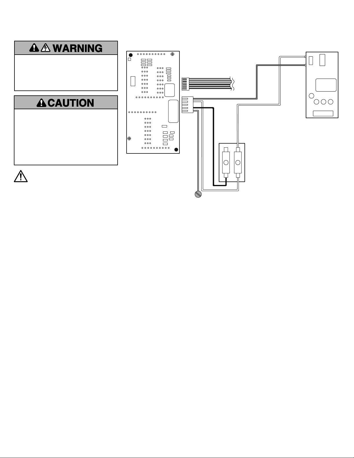
Logic Board
LED Light
Driver Board
To Travel Module
Terminal Block
Ground
White
Orange
Black
White
White
Green
8. Follow the WHITE AND BLACK wires
from the LED driver board and cut the
wire ties.
9. Remove the LED driver board and end
panel.
10. Clip any wire ties from the existing wire
harness.
11. Unplug the WHITE AND BLACK wires
from the terminal block, and remove the
GREEN ground wire.
12. Install the new wire harness.
13. White to white on terminal block, black
to black on terminal block.
14. Attach GREEN ground wire to chassis.
15. Replace travel module wire harness if
necessary.
16. Reinstall LED Driver board end panel.
17. Attach WHITE AND ORANGE wires to
LED driver board.
18. Reconnect wires to logic board.
19. Reconnect WHITE AND BLACK wires
from LED Driver board to logic board
end panel connector plate.
20. Use wire ties to hold all wires together.
21. Reinstall chassis cover to unit.
22. Connect wires to the wire terminal.
a. Door Control Wires:
i. White wire into the white terminal
ii. White/red wire into the red terminal
b. Safety Sensor Wires:
i. White wires into the white terminal
ii. White/black wires into the grey
terminal
23. Make sure the antenna wire is hanging
down.
24. Reattach the LED light pods.

2
Instructions de remplacement de la
faisceau de câblage
Modèle 041D9204
Pour éviter des BLESSURES GRAVES,
VOIRE MORTELLES:
• Débrancher TOUTE alimentation
électrique et la batterie AVANT
d’effectuer TOUT entretien ou TOUTE
intervention.
Avant de commencer
1. Déconnecter l’alimentation électrique et
la batterie (le cas échéant) connectée à
l’ouvre-porte de garage.
2. Enlever les modules d’éclairage à DEL.
a. Tirer sur les côtés supérieurs du
diffuseur et tourner ce dernier vers le
bas.
b. Débrancher le module d’éclairage à
DEL en pinçant le connecteur.
c. Pincer les attaches du diffuseur pour
le retirer du panneau d’extrémité.
3. Enlever les 8vis qui retiennent le
couvercle du châssis et enlever celui-ci.
4. Déconnecter les fils de la cosse de câble.
5. Enlever les vis du panneau d’extrémité.
6. Débrancher le faisceau de fils de la carte
logique et du panneau d’extrémité.
7. Débrancher les fils ORANGE ET BLANC
de la carte du circuit d’éclairage à DEL.
• Pour empêcher tout dommage à la
carte logique du récepteur, NE PAS
toucher le circuit imprimé de la carte
logique du récepteur de remplacement
durant l’installation.
• Porter TOUJOURS des gants de
protection et des lunettes de sécurité
lors du remplacement de la batterie ou
d’une intervention à proximité du
compartiment de la batterie.
AVERTISSEMENT : Ce produit
peut vous exposer à des produits
chimiques comme le plomb,
reconnu par l’État de la Californie
comme cause de cancers,
d’anomalies congénitales et d’autres
problèmes liés à la reproduction.
Pour plus d’informations, visitez
www.P65Warnings.ca.gov.
Carte logique
Carte du circuit
de la lampe à DEL
Avec le module de commande de la course
Bornier
Tierra
Blanc
Orange
Noir
Blanc
Blanc
Vert
8. Suivre les fils BLANC ET NOIR de la carte
du circuit d’éclairage à DEL et couper les
serre-fils.
9. Enlever la carte du circuit d’éclairage à
DEL et le panneau d’extrémité.
10. Couper tout serre-fils qui retient le
faisceau de fils existant.
11. Débrancher les fils BLANC ET NOIR du
bornier et enlever le fil de masse VERT.
12. Installer le faisceau de câblage neuf.
13. Blanc à blanc sur le bornier, noir à noir
sur le bornier.
14. Fixer le fil de masse VERT au châssis.
15. Remplacer le faisceau de fils du module
de cours au besoin.
16. Réinstaller le panneau d’extrémité de la
carte du circuit d’éclairage à DEL.
17. Attacher les fils BLANC ET ORANGE à
carte du circuit d’éclairage à DEL.
18. Reconnecter les fils à la carte logique
19. Reconnecter les fils BLANC ET NOIR de
la carte du circuit d’éclairage à DEL à la
plaque du connecteur du panneau
d’extrémité de la carte logique.
20. Se servir de serre-fils pour retenir tous
les fils ensemble.
21. Remettre le couvercle du châssis sur
l’unité.
22. Connecter les fils à la cosse de câble.
a. Fils de commande de la porte:
i. Fil blanc sur la cosse blanche
ii. Fil blanc/rouge sur la cosse rouge
b. Fils de détecteur-inverseur de sécurité :
i. Fils blancs sur la cosse blanche
ii. Fils blanc/noir sur la cosse grise.
23. S’assurer que le fil de l’antenne pend
tout droit.
24. Remettre en place les modules
d’éclairage à DEL.

3
Instrucciones para reemplazar el arnés
de cables
Modelo 041D9204
Para evitar posibles LESIONES GRAVES
o la MUERTE:
• Desconecte TOTALMENTE la corriente
eléctrica y de la batería ANTES de
realizar CUALQUIER servicio o
mantenimiento.
Antes de comenzar
1. Desconecte la energía eléctrica y la
batería (si corresponde) del abre-puertas
de garaje.
2. Retire los pods de luces LED.
a. Tire los laterales superiores de la lente
de luz y gire la lente hacia abajo.
b. Desenchufe el conector del pod de luz
LED oprimiendo el conector.
c. Oprima los broches de la lente de luz
para retirar la lente del panel extremo.
3. Retire los 8 tornillos que sujetan la
cubierta del chasis y retire la cubierta.
4. Desconecte los cables de la terminal de
cables.
5. Retire los tornillos del panel del extremo.
6. Desenchufe los arneses de cableado del
tablero lógico y del panel extremo.
7. Desenchufe los cables ANARANJADO Y
BLANCO del tablero controlador de LED.
• Para prevenir daños en el receptor/
tablero lógico, NO toque el tablero de
circuito impreso de reemplazo del
receptor/tablero lógico durante la
instalación.
• Use SIEMPRE guantes protectores y
protección para la vista al cambiar la
batería o al trabajar cerca del
compartimiento de la batería.
ADVERTENCIA: Este producto
puede exponerle a productos
químicos (incluido el plomo), que a
consideración del estado de California
causan cáncer, defectos congénitos
u otros daños reproductivos.
Para más información, visite
www.P65Warnings.ca.gov.
Tablero lógico
Tablero controlador
de luz LED
Con el módulo de desplazamiento
Bloque de terminales
Tierra
Blanco
Anaranjado
Negro
Blanco
Blanco
Verde
8. Siga los cables BLANCO Y NEGRO desde
el tablero controlador de LED y corte los
amarres de cable.
9. Retire el tablero controlador de LED y el
panel del extremo.
10. Corte los amarres de cables del arnés de
cables existente.
11. Desenchufe los cables BLANCO Y
NEGRO desde el bloque de terminales y
retire el cable VERDE de puesta a tierra.
12. Instale el arnés de cables nuevo.
13. Blanco a blanco en el bloque de
terminales, negro a negro en el bloque
de terminales.
14. Conecte el cable VERDE de puesta a
tierra al chasis.
15. Reemplace el arnés de cables del
módulo de recorrido, si es necesario.
16. Vuelva a instalar el panel del extremo del
tablero controlador de LED.
17. Conecte los cables BLANCO Y
ANARANJADO al tablero controlador de
LED.
18. Vuelva a conectar los cables al tablero
lógico.
19. Vuelva a conectar los cables BLANCO y
NEGRO desde el tablero controlador de
LED hasta la placa conectora del panel
del extremo del tablero lógico.
20. Use los amarres de cables para sostener
todos los cables.
21. Vuelva a instalar la cubierta del chasis en
la unidad.
22. Conecte los cables a la terminal de
cables.
a. Cables de control de la puerta:
i. Cable blanco en la terminal blanca.
ii. Cable blanco y rojo en la terminal
roja.
b. Cables del sensor de seguridad:
i. Cable blanco en la terminal blanca.
ii. Cables blanco y negro en la
terminal gris.
23. Asegúrese de que el cable de la antena
cuelgue recto hacia abajo.
24. Vuelva a fijar los pods de luz LED.

© 2018, The Chamberlain Group, Inc.
All rights reserved
Tous droits réservés
Todos los derechos reservados
114A5175