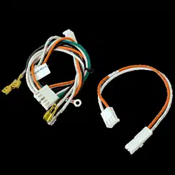
Wire Harness Replacement
Repair Parts 041-0180-000, 041-0181-000
To prevent possible SERIOUS INJURY or DEATH:
• Disconnect ALL electric and battery power BEFORE performing ANY
service or maintenance.
To prevent damage to the receiver/logic board, DO NOT touch printed
circuit board of replacement receiver/logic board during installation.
ALWAYS wear protective gloves and eye protection when changing the
battery or working around the battery compartment.
WARNING: This product can expose you to chemicals including
lead, which are known to the State of California to cause cancer or
birth defects or other reproductive harm. For more information go to
www.P65Warnings.ca.gov.
Introduction
Use this instruction to replace the integrated LED light module cover. The
images throughout this manual are for reference only and your product may
look different.
You will need:
• 1/4" magnetic nut driver
• Long-nosed pliers
• 5/16" long-shafted magnetic nut driver and socket
• Flathead screwdriver
Instructions
The images throughout this manual are for reference only and your product
may look different.
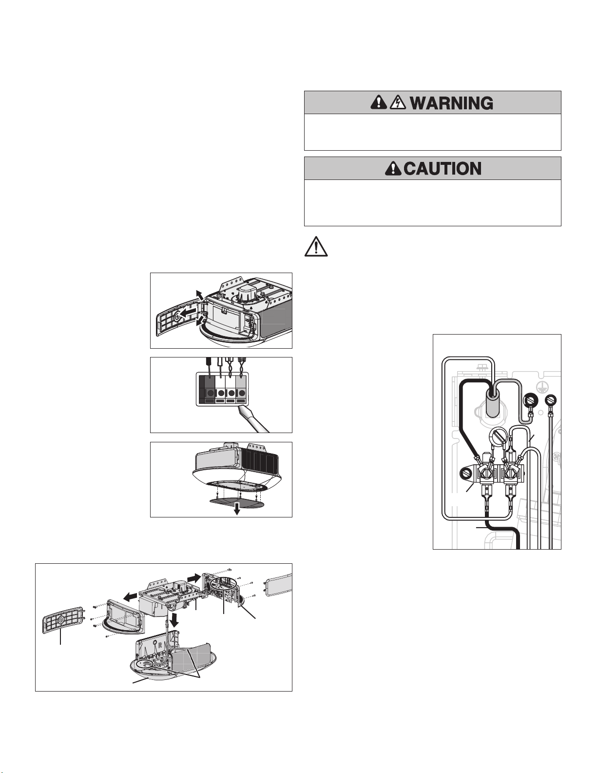
1. Disconnect the electrical and battery power (if applicable) to the garage
door opener. Remove the battery and place in a safe location.
2. Remove the control door panel from both ends of the opener.
Refer to Figure 1.
a. Squeeze or separate
hinges depending on the
style of operator.
b. Remove the control door
panel from the hinge
setting, and place in a
safe location.
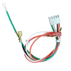
3. Disconnect the door control
wires from the RED and
WHITE terminals and the
Safety Reversal Sensor wires
from the BLACK and WHITE
terminals. Figure 2.
4. Remove the end panels from
both ends of the opener.
5. Remove decorative ring
from opener (applicable
units). Figure 3.
6. Remove the integrated LED
light module cover from the
opener. Figure 4.
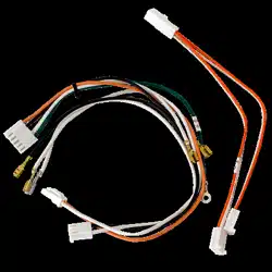
7. Disconnect the ORANGE and
WHITE wire harness from
plug to the Integrated LED
light module and set aside cover / integrated LED light module. Figure 4
(A).
8. Remove the wire harness:
a. Unplug the 4-wire harness (ORANGE, BLACK, WHITE, GREEN) from the
receiver logic board. Figure 4 (B).
b. Unplug the WHITE and BLACK wires from the terminal block.
Refer to Figure 5.
c. Remove the GREEN
ground wire.
8. Attach the new wire harness.
a. Attach the ORANGE and
WHITE wire harness from
plug to the integrated LED
light module.
b. Attach the GREEN
ground wire.
c. Plug in the 4-wire harness
(ORANGE, BLACK, WHITE,
GREEN) from the receiver
logic board. Figure 3 (B).
d. Plug in the WHITE and
BLACK wires from the
terminal block.
e. Bundle and fasten the wires
together with a wire tie.
9. Attach integrated LED light
module.
10. Attach both end panels.
11. Attach decorative ring (applicable units).
12. Reconnect the door control and Safety Reversal Sensor wires. Figure 2.
Door control:
• WHITE wire into the WHITE terminal.
• WHITE/RED wire into the RED terminal.
Safety Reversal Sensors:
• WHITE wires into the WHITE terminal.
• WHITE/BLACK wires into the GRAY terminal.
13. Reattach the control door panels.
14. Reconnect power to the opener.
15. Test the Safety Reversal System. Refer to the Owner’s Manual.
RED
WHITE
WHITE
GREY
Figure 2
Figure 3
Figure 1
A
B
Figure 4
Figure 5
Integrated LED Light Module
Control Door Panel
End Panel
Terminal
Block
Black
Wire
White
Wire
Terminal
Block

© 2021, The Chamberlain Group, Inc.
All rights reserved
Tous droits réservés
114-5527-000 Todos los derechos reservados
Faisceau de rechange
Pièces détachées 041-0180-000, 041-0181-000
Pour éviter d’éventuelles BLESSURES GRAVES voire FATALES:
• Débranchez TOUTE l’alimentation électrique et de la batterie AVANT
d’effectuer TOUT service ou entretien.
Pour éviter d’endommager le récepteur/la carte mère, ne touchez PAS le circuit
imprimé du récepteur/de la carte mère de remplacement pendant l’installation.
Portez TOUJOURS des gants et des lunettes de protection lorsque vous changez
la batterie ou que vous travaillez autour du compartiment de la batterie.
AVERTISSEMENT: Ce produit peut vous exposer à des produits
chimiques, dont le plomb, qui sont reconnus par l’État de Californie
comme provoquant le cancer, des malformations congénitales ou
d’autres problèmes de reproduction. Pour plus d’information, visitez
www.P65Warnings.ca.gov
Introduction
Utilisez ces instructions pour remplacer le couvercle du module intégré
d’éclairage à DEL. Les images de ce manuel sont fournies à titre indicatif
uniquement et il est possible que votre produit soit différent.
Vous aurez besoin de ce qui suit:
• Tourne-écrou magnétique 1/4po
• Pinces à long bec
• Tourne-écrou magnétique à manche long 5/16po et douille
• Tournevis à tête plate
Instructions
Les images de ce manuel sont fournies à titre indicatif uniquement et il est
possible que votre produit soit différent.
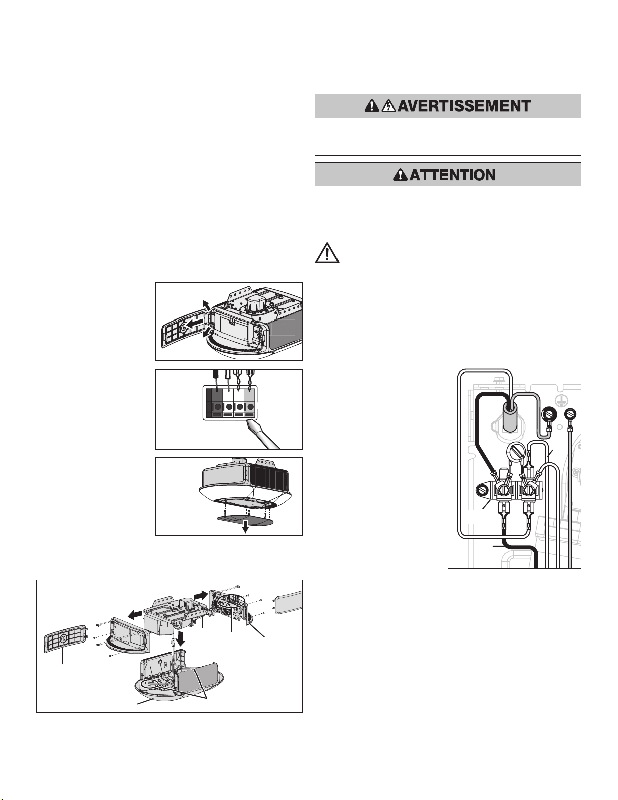
1. Débranchez l’alimentation électrique et la batterie de l’ouvre-porte de
garage (le cas échéant). Retirez la batterie et mettez-la dans un endroit sûr.
2. Retirez le panneau de la porte de commande de chaque côté de l’ouvre-porte.
Voir la Figure1.
a. Pressez ou séparez les
charnières selon le type
d’opérateur
b. Retirez le panneau de la
porte de commande de
ses charnières et mettez-
le dans un endroit sûr.
3. Débranchez les fils de
commande de la porte des
bornes ROUGE et BLANCHE et
les fils du capteur d’inversion
de sécurité des bornes NOIRE
et BLANCHE. Figure2.
4. Retirez le panneau
d’extrémité de chaque côté
de l’ouvre-porte.
5. Retirez l’anneau décoratif de
l’ouvre-porte (unités qui en
sont munies). Figure3.
6. Retirez le couvercle du module
intégré d’éclairage à DEL de
l’ouvre-porte. Figure 4.
7. Débranchez le faisceau de câbles ORANGE et BLANC de la prise du module
intégré d’éclairage à DEL et mettez le couvercle/module d’éclairage à DEL
de côté. Figure4 (A).
8. Retirer le faisceau:
a. Débranchez le faisceau de 4fils (ORANGE, NOIR, BLANC, VERT) de la
carte mère du récepteur. Figure4 (B).
b. Débranchez les fils BLANC et NOIR du bornier.
Voir la Figure5.
c. Retirez le fil de terre VERT.
8. Fixez le nouveau faisceau de fils.
a. Fixez le faisceau de fils
ORANGE et BLANC de la
prise au module intégré
d’éclairage à DEL.
b. Fixez le fil à terre VERT.
c. Branchez le faisceau de 4fils
(ORANGE, NOIR, BLANC,
VERT) de la carte mère du
récepteur. Figure3 (B).
d. Branchez les fils BLANC et
NOIR du bornier.
e. Groupez et attachez les fils
ensemble à l’aide d’un fil
métallique d’attache.
9. Fixez le module intégré
d’éclairage à DEL
10. Remettez en place les deux
panneaux d’extrémité.
11. Fixer l’anneau décoratif (unités
qui en sont munies)
12. Reconnectez les fils de la commande de porte et du capteur d’inversion de
sécurité. Figure2.
Contrôle de porte:
• Fil BLANC dans la borne BLANCHE.
• Fil BLANC/ROUGE dans la borne ROUGE.
Capteurs d’inversion de sécurité:
• Fils BLANCS dans la borne BLANCHE.
• Fils BLANCS/NOIRS dans la borne GRISE.
13. Remettez en place le panneau de la porte de commande.
14. Rebranchez l’alimentation à l’ouvre-porte.
15. Faites un test pour vérifier le système d’inversion de sécurité. Reportez-vous
au manuel d’utilisation.
ROUGE
BLANC
BLANC
GRIS
Figure2
Figure3
Figure1
A
B
Figure4
Figure5
Module intégré d’éclairage à DEL
Panneau de la porte de commande
Panneau d’extrémité
Bornier
Fil
noir
Fil
blanc
Bornier

© 2021, The Chamberlain Group, Inc.
All rights reserved
Tous droits réservés
114-5527-000 Todos los derechos reservados
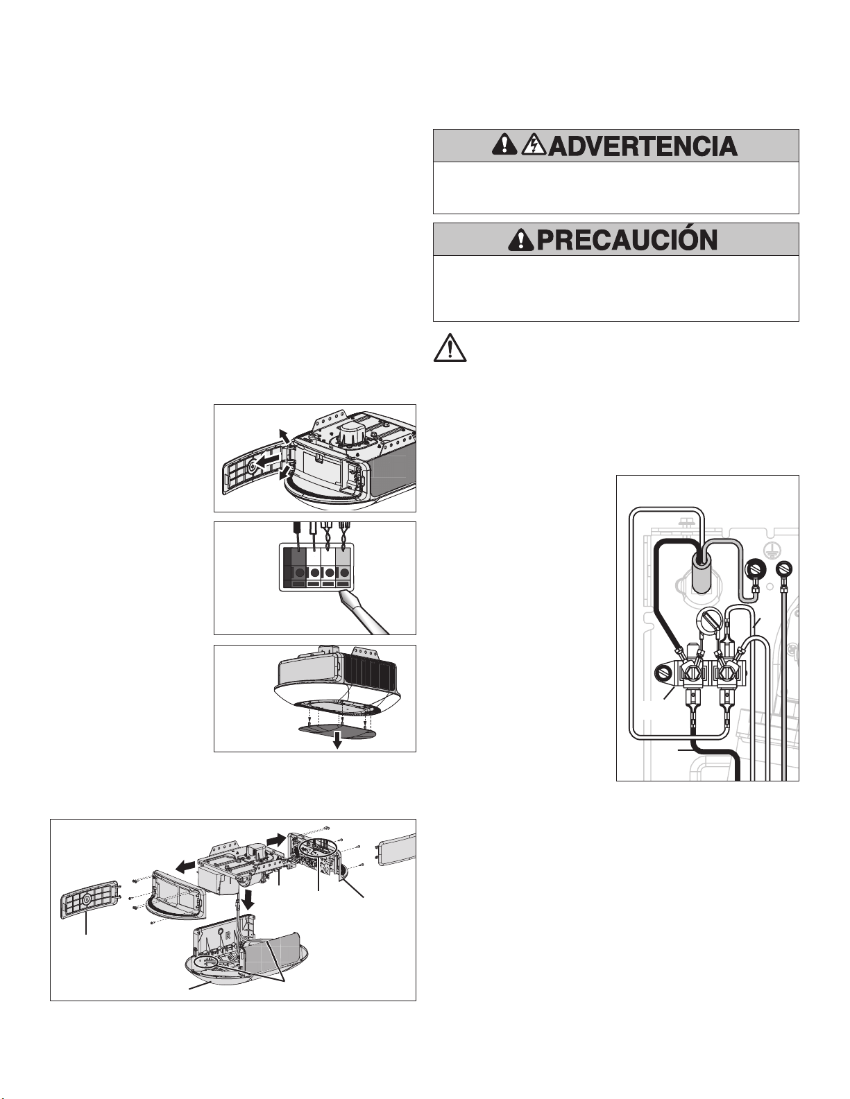
Reeplazo del arnés del cable
Piezas de repuesto 041-0180-000 y 041-0181-000
Para evitar posibles LESIONES GRAVES o la MUERTE:
• Desconecte TODA alimentación eléctrica y de batería ANTES de realizar
CUALQUIER servicio o mantenimiento.
Para evitar daños al receptor/tarjeta lógica, NO toque el circuito impreso de
la tarjeta en el receptor/tarjeta lógica de repuesto durante la instalación.
Use SIEMPRE guantes protectores y protectores para la vista al cargar la
batería o al trabajar cerca del compartimento de la batería.
ADVERTENCIA: Este producto podría exponerlo a sustancias
químicas, incluido el plomo, que el estado de California conoce
como causantes de cáncer, defectos de nacimiento u otros
daños reproductivos. Para obtener más información, visite
www.P65Warnings.ca.gov.
Introducción
Use estas instrucciones para reemplazar la cubierta del módulo de la lámpara
con LED integrado. Las imágenes de este manual son de referencia únicamente
y su producto podría tener un aspecto diferente.
Necesitará:
• Llave de tuerca magnética de 1/4"
• Pinza de punta
• Llave de tuerca magnética de cuello largo de 5/16" y vaso
• Destornillador de cabeza plana
Instrucciones
Las imágenes utilizadas en este manual son solo como referencia y su producto
puede verse diferente.
1. Desconecte la alimentación eléctrica y de batería (si corresponde) al
abrepuertas de garaje. Quite la batería y colóquela en un lugar seguro.
2. Quite el panel de control de ambos extremos del abrepuertas.
Consulte la Figura 1.
a. Apriete o separe las
bisagras en función del
estilo del operador.
b. Quite el panel de control
de la puerta del conjunto
de bisagras y colóquelo
en un lugar seguro.
3. Desconecte los cables de
control de la puerta de los
terminales ROJO y BLANCO
y los cables del sensor de
inversión de seguridad de
los terminales NEGRO y
BLANCO. Figura 2.
4. Quite los paneles del
extremo de ambos extremos
del abrepuertas.
5. Quite el anillo decorativo del
abrepuertas (unidades
correspondientes). Figura 3.
6. Quite la cubierta del módulo
de la lámpara con LED
integrado del abrepuertas.
Figura 4.
7. Desconecte el arnés del cable NARANJA y BLANCO del enchufe al módulo
de la lámpara con LED integrado y aparte la cubierta / el módulo de la
lámpara con LED integrado. Figura 4 (A).
8. Quite el arnés del cable:
a. Desenchufe el arnés de 4 cables (NARANJA, NEGRO, BLANCO, VERDE)
de la tarjeta lógica del receptor. Figura 4 (B).
b. Desenchufe los cables BLANCO y NEGRO del bloque de terminales.
Consulte la Figura 5.
c. Quite el cable VERDE
de conexión a tierra.
8. Conecte el nuevo arnés del cable.
a. Conecte el arnés del cable
NARANJA y BLANCO al
enchufe del módulo de la
lámpara con LED integrado.
b. Conecte el cable VERDE
de conexión a tierra.
c. Desenchufe el arnés de 4
cables (NARANJA, NEGRO,
BLANCO, VERDE) de la
tarjeta lógica del receptor.
Figura 3 (B).
d. Enchufe los cables BLANCO
y NEGRO del bloque de
terminales.
e. Agrupe y sujete los cables
con un precinto.
9. Conecte el módulo de la lámpara
con LED integrado.
10. Coloque ambas cubiertas del panel del extremo.
11. Coloque el anillo decorativo (unidades correspondientes).
12. Vuelva a conectar el control de la puerta y los cables del sensor de inversión
de seguridad. Figura 2.
Control de la puerta:
• Cable BLANCO a terminal BLANCO.
• Cable BLANCO/ROJO a terminal ROJO.
Sensores de inversión de seguridad:
• Cables BLANCOS a terminal BLANCO.
• Cables BLANCO/NEGRO a terminal GRIS.
13. Vuelva a colocar las puertas del panel de control.
14. Vuelva a conectar la alimentación al abrepuertas.
15. Probar el sistema de inversión de seguridad. Consulte el manual del propietario.
ROJO
BLANCO
BLANCO
GRIS
Figura 2
Figura 3
Figura 1
A
B
Figura 4
Figura 5
Lámpara con LED integrado
Puerta del panel de control
Panel del extremo
Bloque del
terminal
Cable
negro
Cable
blanco
Bloque del
terminal

© 2021, The Chamberlain Group, Inc.
All rights reserved
Tous droits réservés
114-5527-000 Todos los derechos reservados