ADDENDUM
470 OHM 3W RESISTOR 156A0184
INSTALLATION FOR VFOH OPERATORS
Installation
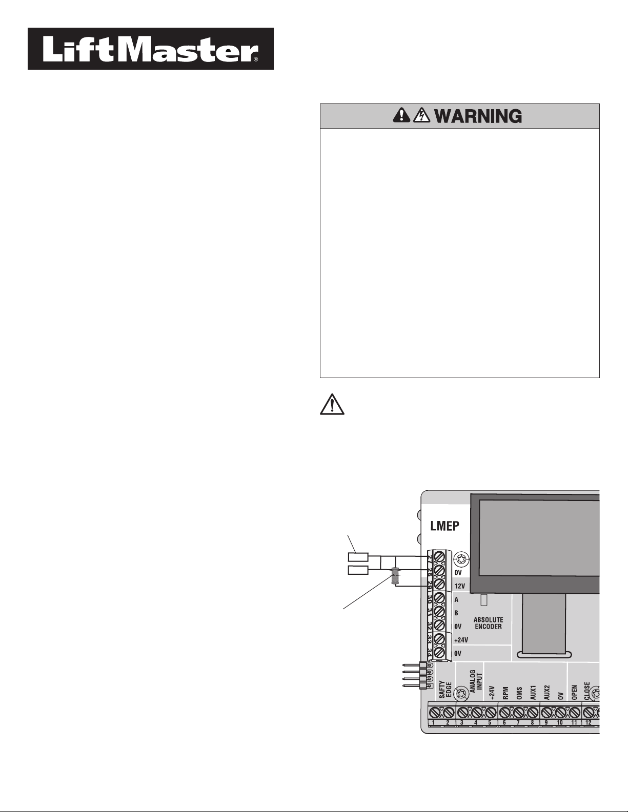
IMPORTANT: Install the resistor during the installation of the photoelectric
sensor wires.
1. Disconnect power to the operator.
2. Loosen terminal screws #27 (LMEP) and #29 (12V).
3. Form and trim the resistor leads as needed.
4. Insert one end of the resistor into pin #27, along with the photoelectric
sensor terminal wires, and tighten the screw.
5. Insert the other end of the resistor into pin #29, along with the solid
Orange encoder wire, and tighten the terminal #29 screw.
6. Ensure the encoder wire and resistor lead are secure.
7. Power up the operator. Ensure the photoelectric sensor green LEDs
glow solid green.
8. Test by activating the operator.
To prevent possible SERIOUS INJURY or DEATH from a closing door:
• Be sure power is NOT connected to the door operator BEFORE installing
the LiftMaster Monitored Entrapment Protection Device(s).
• The door MUST be in the fully opened or closed position BEFORE
installing the LiftMaster Monitored Entrapment Protection Device(s).
To prevent SERIOUS INJURY, DEATH, ENTRAPMENT, or PROPERTY
DAMAGE:
• Correctly connect and align the photoelectric sensor.
• Install the primary monitored photoelectric sensor beam NO HIGHER
than 6" (15 cm) above the floor.
• This is a required LMEP Device for B2, TS, and T wiring types and
MUST NOT be disabled. For C2 wiring the installation of an entrapment
protection device is recommended.
• LiftMaster Monitored Entrapment Protection Devices are for use with
LiftMaster commercial door operators ONLY. Use with ANY other
product voids the warranty.
• If an edge sensor is being used on a vertical moving door, place edge
sensors on the bottom edge of the door.
Resistor
Photoelectric sensors
Introduction
Use this addendum in conjunction with the supporting documentation
included with Variable Speed Front of Hood (VFOH) operator. Apply this
installation instruction addendum at the Entrapment Protection section of
the VFOH Installation Manual. For all other instructions, refer to the
supporting documentation included with your operator.
Install the 470 OHM, 3W Resistor for the Variable Speed Front of Hood
(VFOH) operator. Models include:
• VFOH5011 1/2 HP (120 Single Phase)
• VFOH5021 1/2 HP (240V/230V Single Phase/Three Phase)
• VFOH5045 1/2 HP (460V/575V Three Phase (via separate Stepdown
Transformer))
Carton Inventory
• (1) 470 OHM, 3W Resistor
WARNING: This product can expose you to chemicals including
lead, which are known to the State of California to cause cancer or
birth defects or other reproductive harm. For more information go
to www.P65Warnings.ca.gov.
Recommended Tools
• Flat screw drivers
• Wire cutter/stripper
© 2021, The Chamberlain Group, Inc.
All Rights Reserved
114-5544-000
