• Please read this manual and the enclosed safety materials carefully!
• Fasten the manual near the garage door after installation.
• The door WILL NOT CLOSE unless the Protector System
®
and cable tension monitor
are connected and properly aligned.
• Periodic checks of the garage door opener are required to ensure safe operation.
• The model number label is located behind the hinged door of your opener.
• DO NOT exceed 10 complete cycles of door operation per hour.
• This garage door opener is ONLY compatible with myQ
®
and Security+ 2.0
®
accessories.
This product is intended for installation only by trained garage door technicians. This
product may require adjustments to door springs and or track configurations. This
product is not intended for use on low headroom tracks or garage doors utilizing
extension springs.
For Residential and Light Duty Commercial Use
Install On Sectional Doors With Torsion Assemblies Only
S
e
e
P
a
g
e
1
8
f
o
r
D
e
t
a
i
l
s
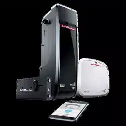
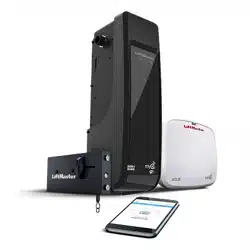
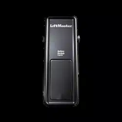
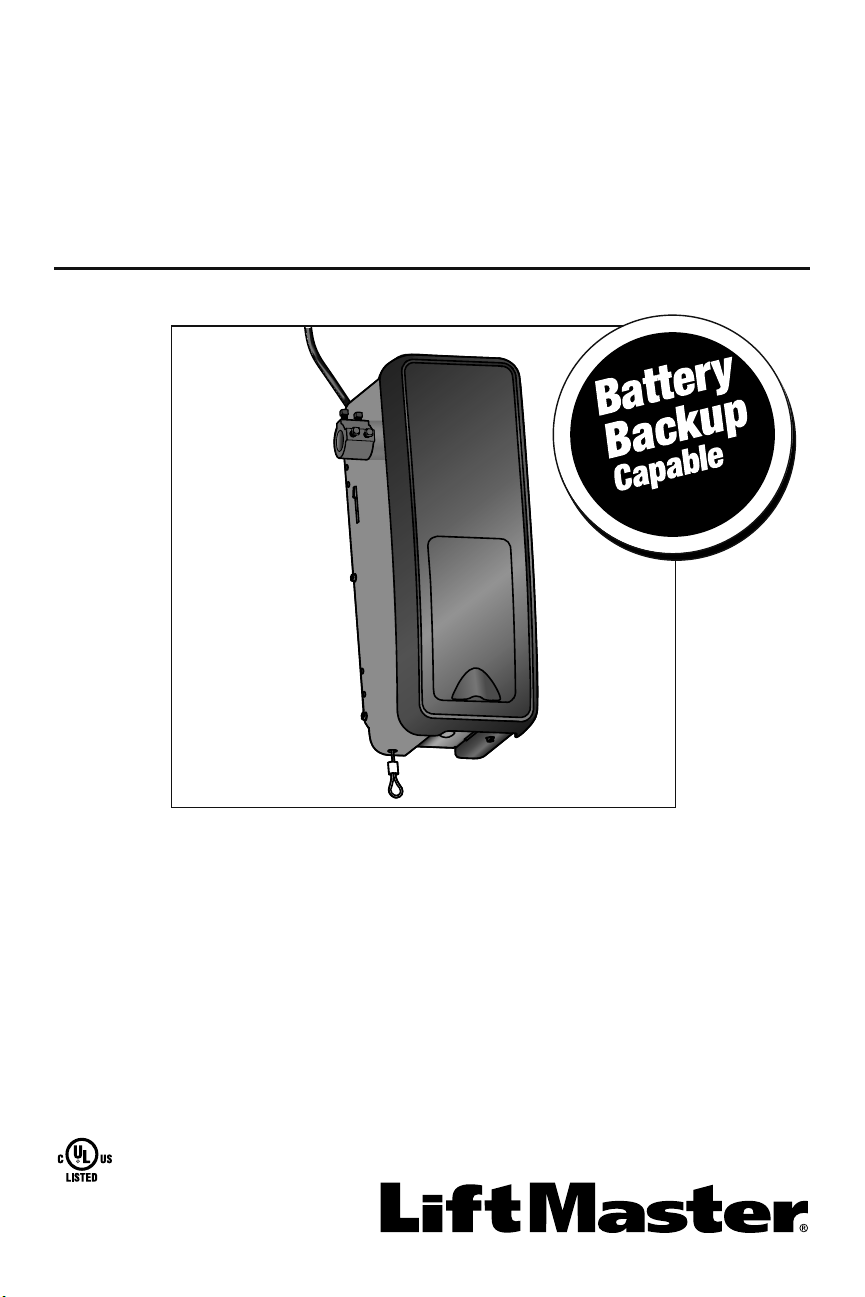
Wall Mount Garage Door Opener
Model 8500
LiftMaster
300 Windsor Drive
Oak Brook, IL 60523

2
Introduction
When you see these Safety Symbols and Signal Words on the following pages, they
will alert you to the possibility of serious injury or death if you do not comply with the
warnings that accompany them. The hazard may come from something mechanical or
from electric shock. Read the warnings carefully.
When you see this Signal Word on the following pages, it will alert you to the possibility
of damage to your garage door and/or the garage door opener if you do not comply with
the cautionary statements that accompany it. Read them carefully.
Mechanical
Electrical
Safety Symbol and Signal Word Review
This garage door opener has been designed and tested to offer safe service provided it is installed, operated, maintained and tested in
strict accordance with the instructions and warnings contained in this manual.
Table of Contents
INTRODUCTION 2
Safety Symbol and Signal Word Review ...2
Planning ....................................................3
Preparing Your Garage Door .....................4
Tools Needed ............................................4
Carton Inventory .......................................5
Hardware ..................................................5
ASSEMBLY 6
Attach the Collar to the
Garage Door Opener .................................6
Attach Mounting Bracket to
Garage Door Opener .................................7
INSTALLATION 7
Position and Mount the
Garage Door Opener .................................8
Attach the Emergency Release Rope
and Handle ................................................9
Install Power Door Lock ............................9
Attach the Cable Tension Monitor
(Required) ...............................................10
Install the Door Control
(myQ Control Panel) ...............................11
Install Remote Light ................................12
Install the Protector System
®
.................13
Connect Power ........................................16
Install the Battery Backup (optional) .......18
ADJUSTMENT 19
Program the Travel Limits .......................19
Set the Force ...........................................20
Test the Safety Reversal System .............21
Test the Protector System
®
....................21
Test Cable Tension Monitor ....................22
Test Power Door Lock .............................22
To Open the Door Manually ....................22
OPERATION 23
Using Your Garage Door Opener .............23
Using the Door Control
(myQ Control Panel) ...............................24
Using the Remote Control .......................25
PROGRAMMING 26
To Add a Remote Control,
Keyless Entry, or myQ Enabled Accessories
using the
Door Control (myQ Control Panel) ..........26
LiftMaster
®
Internet Gateway
(Not Provided) ........................................27
To Erase All Codes From the
Door Control (myQ Control Panel)
Memory ..................................................27
Reprogramming Light or
Additional Light .......................................27
Additional Programming for the Keyless
Entry (Not Provided) ...............................28
HomeLink
®
..............................................28
MAINTENANCE ......................... 29
Care of Your Garage Door Opener ...........29
TROUBLESHOOTING 30
Diagnostic Chart .....................................30
Troubleshooting ......................................31
Troubleshooting (Continued) ..................32
REPAIR PARTS 33
Installation Parts .....................................33
Garage Door Opener Assembly Parts ......34
CONTACT INFORMATION 34
ACCESSORIES 35
WARRANTY 36
Automatic Garage Door Opener
Safety & Maintenance Guide 37
WARNING: This product can expose you to chemicals including lead, which are known to the State of California to cause
cancer or birth defects or other reproductive harm. For more information go to www.P65Warnings.ca.gov.
3
Planning
Survey your garage area to see if any of the conditions below apply to your installation.
Depending on your requirements, additional materials may be required.
THIS GARAGE DOOR OPENER IS COMPATIBLE WITH:
• Doors that use a torsion bar and springs. The torsion bar must be 1 inch (2.5 cm)
diameter.
• 4-6 inch (10-15 cm) drums, not to be used on tapered drums over 6 inches (15 cm).
• 3 to 3.9 inch (7.6cm to 9.9cm) drums may be used on doors up to 430lbs.
(195.4Kgs)
• High lift (up to 54 inches (137.2 cm) high) and standard lift sectional doors up to
14 feet (4.3 m) high.
• Doors up to 18 feet (5.5 m) wide.
• Doors up to 180 sq. ft. (16.7 sq. m).
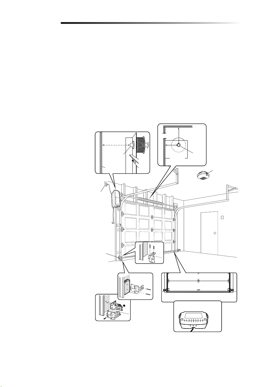
Review or inspect proposed installation
area. The garage door opener can be
installed on the left or right side of door.
Select the side that meets the requirements
listed below.
a. Must have minimum of 2-1/2 inches
(6.4 cm) between the garage wall and
the center of the torsion bar.
b. Must have minimum of 3 inches
(7.6 cm) between the ceiling and the
center of torsion bar.
c. Must have minimum of 8.5 inches
(21.6 cm) between the side garage
wall (or obstruction) and the end of
torsion bar.
d. The torsion bar must extend at least
1-1/2 inches (3.81 cm) past the
bearing. This may vary depending on
your installation requirements.
e. An electric outlet is required within
6 feet (1.83 m) of the installation
area. If outlet does not exist, contact
a qualified electrician or use a low
voltage power supply (model 580LM).
f. Depending upon garage construction,
extension brackets or wood blocks
may be needed to install safety
reversing sensors.
g. Alternate floor mounting of the
safety reversing sensors will require
hardware (not provided).
h. Any gap between the floor and the
bottom of the door must not exceed
1/4 inch (6 mm). Otherwise, the
safety reversal system may not work
properly.
i. A model 475LM Battery Backup is
strongly recommended if there is
no access door to the garage, as
this garage door opener cannot be
used in conjunction with an external
emergency release mechanism.
Introduction
NOTE: Inspect the torsion bar while the
door is raised and lowered. It is important
that there is no noticeable movement up
and down or left and right. If the movement
is not corrected, the life of the garage door
opener will be greatly reduced.
a
b
h
i
c
d
e
f
g
Torsion
bar
2-1/2
inches
(6.4 cm)
3 inches
(7.6 cm)
Wall or
obstruction
Torsion bar
8.5 inches
(21.6 cm)
475LM Battery Backup
Safety
reversing
sensor
Remote light
4
Introduction
Preparing Your Garage
Door
BEFORE YOU BEGIN:
• Disable locks.
• Remove any ropes connected to the
garage door.
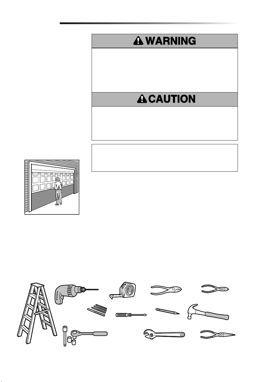
Complete the following test to make sure
the garage door is balanced and is not
sticking or binding:
1. Lift the door halfway up. Release
the door. If balanced, it should stay
in place, supported entirely by its
springs.
2. Raise and lower the door to check for
binding or sticking.
If your door binds, sticks, or is out of
balance, call a trained door systems
technician.
To prevent damage to garage door and opener:
• ALWAYS disable locks BEFORE installing and operating the opener.
• ONLY operate garage door opener at 120 V, 60Hz to avoid malfunction and
damage.
• DO NOT exceed 10 complete cycles of door operation per hour.
To prevent possible SERIOUS INJURY or DEATH:
• ALWAYS call a trained door systems technician if garage door binds, sticks, or is
out of balance. An unbalanced garage door may NOT reverse when required.
• NEVER try to loosen, move or adjust garage door, door springs, cables, pulleys,
brackets or their hardware, ALL of which are under EXTREME tension.
• Disable ALL locks and remove ALL ropes connected to garage door BEFORE
installing and operating garage door opener to avoid entanglement.
Tools Needed
During assembly, installation and adjustment of the garage door opener, instructions will
call for hand tools as illustrated below.
Specifications
Volts ............................................120 Vac - 60 Hz, ONLY
Current .....................................................1.0 AMP
Pliers
Wire Cutters
Claw Hammer
Screwdriver
Adjustable End Wrench
1/4", 5/16" and 3/8" Sockets
and Wrench with 6" Extension
Drill
Tape Measure
Stepladder
Pencil
Needle Nose Pliers
5/32", 3/16", 5/16"
and 3/4" Drill Bits
Sectional Door
Torque Meter (not shown)
5
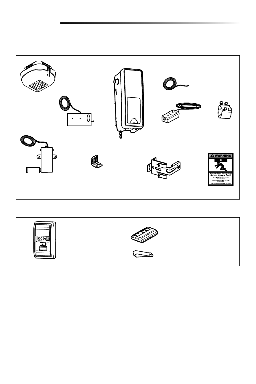
Carton Inventory
Included Accessories
Introduction
Remote Control Visor Clip
3-Button Premium Remote Control
Model 893MAX (1)
Remote Light
(Garage Door Opener Light)
with Hardware Bag
Power Door Lock with
2-Conductor White &
White/Black Bell Wire
with Connector
2 Conductor Bell
Wire White &
White/Red
Garage Door
Opener
Cable Tension Monitor
with 2-Conductor
Green/White Bell Wires
Mounting
Bracket
Collar with
Set Screws
Safety Reversing Sensor
Bracket (2)
The Protector System
®
(2) Safety Reversing Sensors
(1 Sending Sensor and 1
Receiving Sensor) with
2-Conductor White & White/
Black Bell Wire attached
Safety Labels
and Literature
Hardware
Accessories included with the garage door opener will vary depending on the model purchased. If anything is missing, carefully check
the packing material.
Door Control (myQ Control Panel)
Model 889LM
Screw #10-32 (2)
Screw 14-10x2" (4)
Handle
Rope
Screw 1/4"-20x1/2" (2)
Drywall Anchor (Screw-In) (2)
Screw 8-32x1" (2)
Screw 6ABx1-1/4" (2)
Drywall Anchor (2)
Screw 6-32x1" (2)
Carriage Bolt 1/4"-20x1/2" (2)
Wing Nut 1/4"-20 (2)
REMOTE LIGHT HARDWARE:
Drywall Anchor (Screw-In) (2)
Screw #6x1" (2)
Screw #4-20x7/16" (2)
Hinge Clip (1)
Latch Clip (1)
NOT SHOWN: Lock Template
6
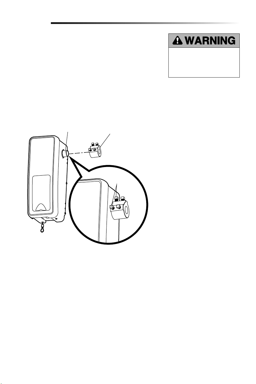
Collar
Motor Shaft
Set Screws
To avoid installation difficulties, do not run the garage door garage door opener until
instructed to do so.
The garage door opener can be installed on either side of the door (see Planning section
page 3). The illustrations shown are for installation on the left side.
1.
Loosen the set screws.
2. Attach collar to the garage door opener motor shaft. The side of the collar with the
larger hole should be placed on the motor shaft. Ensure that the collar is seated all
the way on motor shaft until stop is reached.
3. Position the collar so the screws are facing out and are accessible when attached to
the torsion bar.
4. Securely tighten the 2 square head set screws closest to the motor shaft by turning
the screws 1/4 - 1/2 turn after making contact with the motor shaft.
Attach the Collar to the Garage Door Opener
Assembly
1
To prevent possible SERIOUS INJURY
or DEATH, the collar MUST be properly
tightened. The door may not reverse
correctly or limits may be lost due to
collar slip.
7
Installation
IMPORTANT INSTALLATION INSTRUCTIONS
To reduce the risk of
SEVERE INJURY or DEATH:
1. READ AND FOLLOW ALL INSTALLATION WARNINGS
AND INSTRUCTIONS.
2. Install garage door opener ONLY on properly balanced
and lubricated door. An improperly balanced door may
NOT reverse when required and could result in SEVERE
INJURY or DEATH.
3. ALL repairs to cables, spring assemblies and other
hardware MUST be made by a trained door systems
technician BEFORE installing garage door opener.
4. Disable ALL locks and remove ALL ropes connected to
door BEFORE installing garage door opener to avoid
entanglement.
5. Where possible, install the door operator 7 feet or more
above the floor.
6. Mount the emergency release within reach, but at least
6feet (1.83 m) above the floor and avoiding contact
with vehicles to avoid accidental release.
7. NEVER connect garage door opener to power source
until instructed to do so.
8. NEVER wear watches, rings or loose clothing while
installing or servicing the garage door opener. They
could be caught in door or operator mechanisms.
9. Install wall-mounted door control:
• within sight of the door.
• out of reach of small children at a minimum height
of 5 feet (1.5 m) above floors, landings, steps or
any other adjacent walking surface.
• away from ALL moving parts of the door.
10. Install the Emergency Release Marking. Attach the
marking on or next to the emergency release. Install the
Entrapment Warning Placard next to the door control in
a prominent location.
11. Place emergency release/safety reverse test label in plain
view on inside of door.
12. Upon completion of installation, test safety reversal
system. Door MUST reverse on contact with a 1-1/2"
(3.8 cm) high object (or a 2x4 laid flat) on the floor.
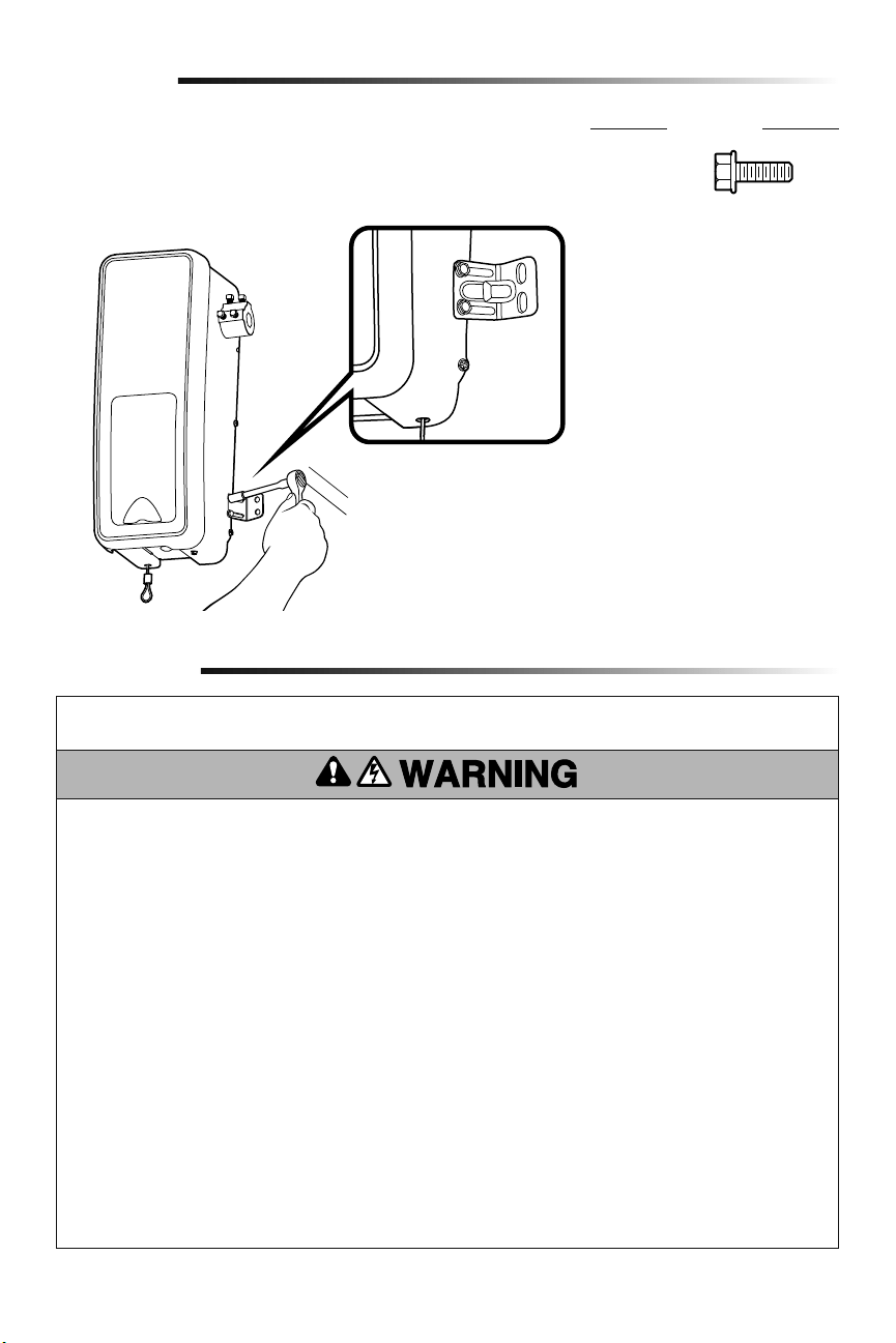
Attach Mounting Bracket to Garage Door Opener
2
1. Loosely attach slotted side of mounting bracket to the same side of the garage door
opener as the collar, using screws provided.
NOTE: Do not tighten screws until instructed.
Socket Wrench
Assembly
HARDWARE
Screw
#10-32 (2)
8
Bearing
Plate
Collar
Torsion Bar
.25" min. space
between
bearing and
collar
Mounting Bracket
Screws 14-10x2"
Set screws
(Torsion bar)
Installation
HARDWARE
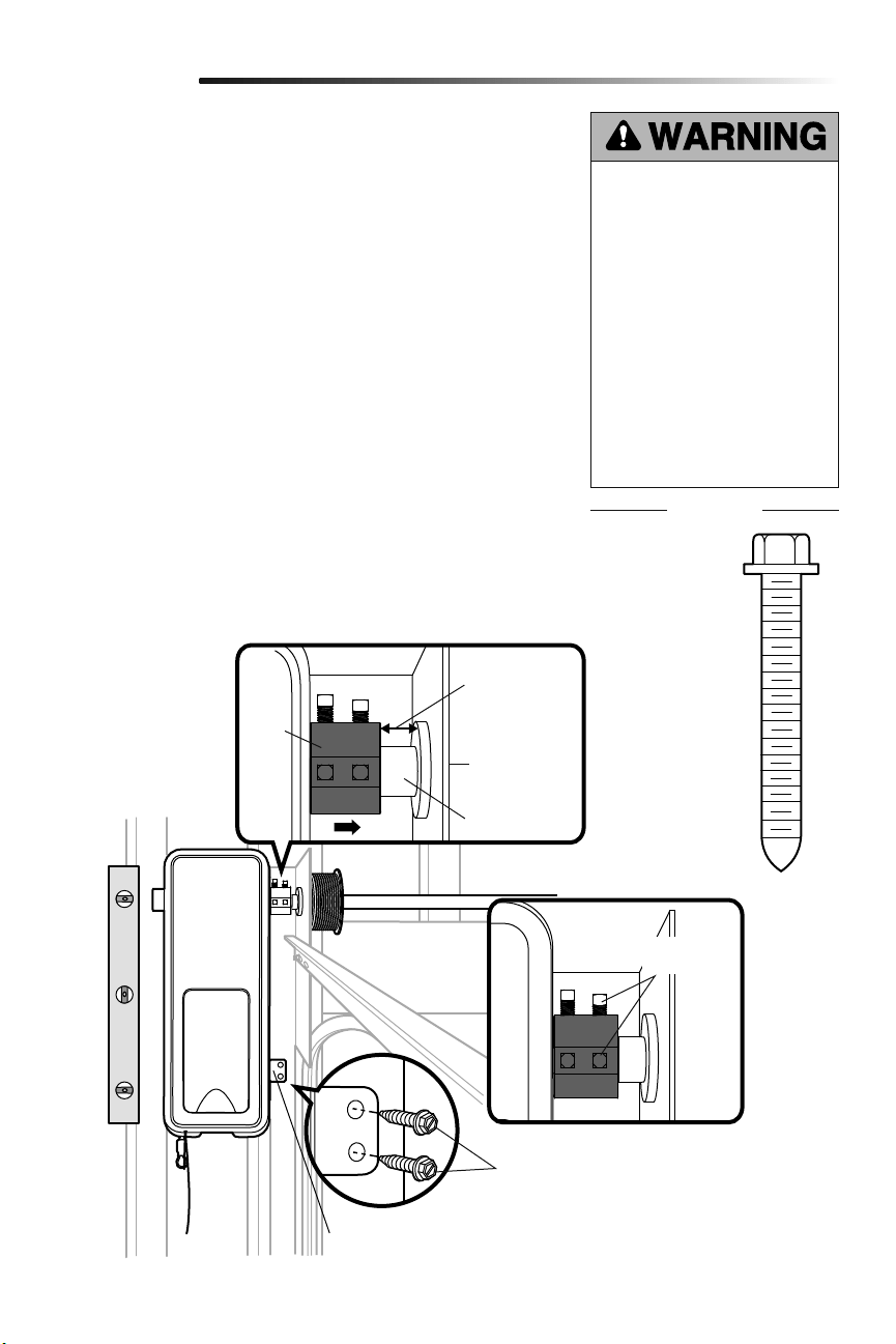
Position and Mount the Garage Door Opener
1
NOTE: For additional mounting options refer to the accessories page.
1. Close the garage door completely.
2.
Slide the garage door opener onto the end of the torsion bar. If the torsion bar is too
long or damaged, you may need to cut the torsion bar.
Ensure the collar does NOT touch the bearing.
3. Use a level to position and vertically align the garage door opener. Verify the
mounting bracket is located on a solid surface such as wood, concrete or door/flag
bracket. If installing on drywall, the mounting bracket MUST be attached to a stud.
4.
When the garage door opener is properly aligned, mark the mounting bracket holes.
If necessary, tighten collar screws on the torsion bar to hold garage door opener in
place while marking holes.
NOTE: The garage door opener does not have to be flush to wall.
5. Remove the garage door opener from torsion bar. Drill 3/16 inch pilot holes at the
marked locations. Drill through metal door rail plates if necessary.
6.
Slide the garage door opener back onto the torsion bar until pilot holes align with
bracket.
7. Tighten the 2 square head set screws on the torsion bar. For a hollow torsion bar,
tighten screws 3/4 - 1 full turn after making contact with the bar. For a solid shaft
torsion bar, tighten screws 1/4 - no more than 1/2 turn after making contact with
the shaft. If installing on a keyed torsion bar, DO NOT tighten the screws into the
keyway.
8. Secure the mounting bracket to the wall and to the garage door opener. Use the
14-10 x 2" screws to secure the mounting bracket to the wall.
To prevent possible SERIOUS INJURY
or DEATH:
• Concrete anchors MUST be used if
mounting bracket into masonry.
• NEVER try to loosen, move or
adjust garage door, springs,
cables, pulleys, brackets or their
hardware, ALL of which are under
EXTREME tension.
• ALWAYS call a trained door
systems technician if garage door
binds, sticks or is out of balance.
An unbalanced garage door might
NOT reverse when required.
• Garage door opener MUST be
mounted at a right angle to the
torsion bar to avoid premature
wear on the collar.
Screw
14-10x2" (2)
9
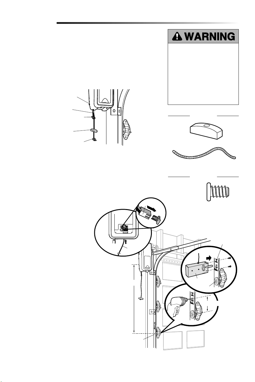
Attach the Emergency Release Rope and Handle
Install Power Door Lock
2
3
1. Thread one end of the rope through the hole in the top of the red handle so
“NOTICE” reads right side up. Secure with an overhand knot at least 1 inch (2.5 cm)
from the end of the rope to prevent slipping.
2. Thread the other end of the rope through the loop in the emergency release cable.
Adjust rope length so the handle is no higher than 6 feet (1.83 m) above the floor.
Secure with an overhand knot.
NOTE: If it is necessary to cut the rope, heat seal the cut end with a match or lighter to
prevent unraveling.
1. The power door lock must be
mounted within 10 feet (3.05m)
of garage door opener with
approximately a 3 inch (7.6 cm)
distance between the center of a door
roller and the hole for the power door
lock bolt. If possible, mount on same
side as garage door opener. The
second roller from the bottom is ideal
for most installations.
2.
Ensure rail surface is clean and attach
lock template to track.
3. Drill holes as marked on the template.
4. Fasten power door lock to the
outside of the garage door track with
hardware provided.
5. Run bell wire up wall to garage door
opener. Use insulated staples to
secure wire in several places. Insert
wire through the bottom of the garage
door opener.
6. Plug the connector into the garage
door opener.
Installation
The power door lock is used to prevent the garage door from being manually opened
once the door is fully closed.
Garage Door
Opener
Emergency
Release Cable
Overhand
Knot
Overhand
Knot
Emergency
Release Handle
To prevent possible SERIOUS INJURY
or DEATH from a falling garage door:
• If possible, use emergency release
handle to disengage door ONLY when
garage door is CLOSED. Weak or
broken springs or unbalanced door
could result in an open door falling
rapidly and/or unexpectedly.
• NEVER use emergency release handle
unless garage doorway is clear of
persons and obstructions.
Roller
Approx. 3" (7.6 cm)
10 feet (3.05 m) max.
Garage Door
Track
Lock
Template
HARDWARE
Screw
1/4"-20x1/2" (2)
Rope
Handle
HARDWARE
Connector
Door Lock
Bell
Wire
10
HARDWARE
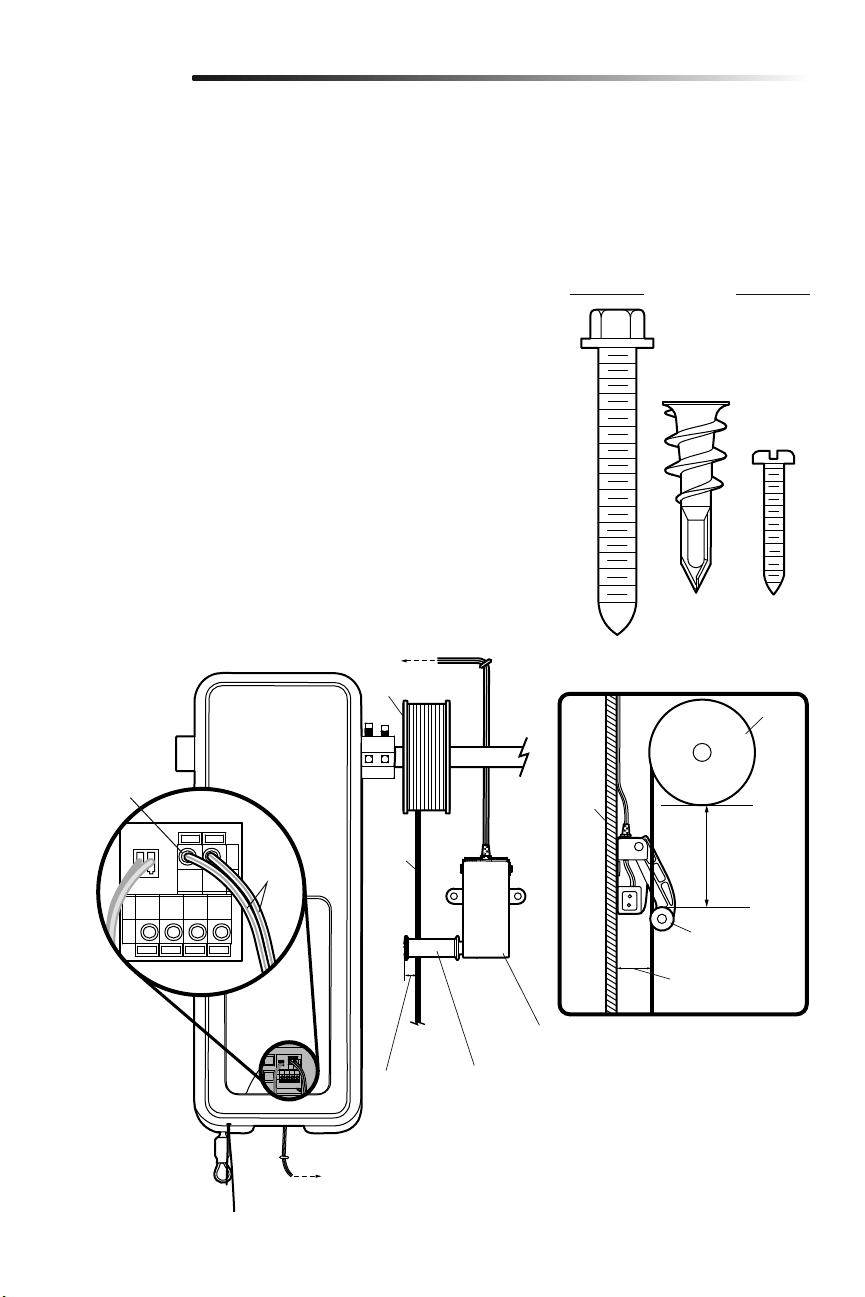
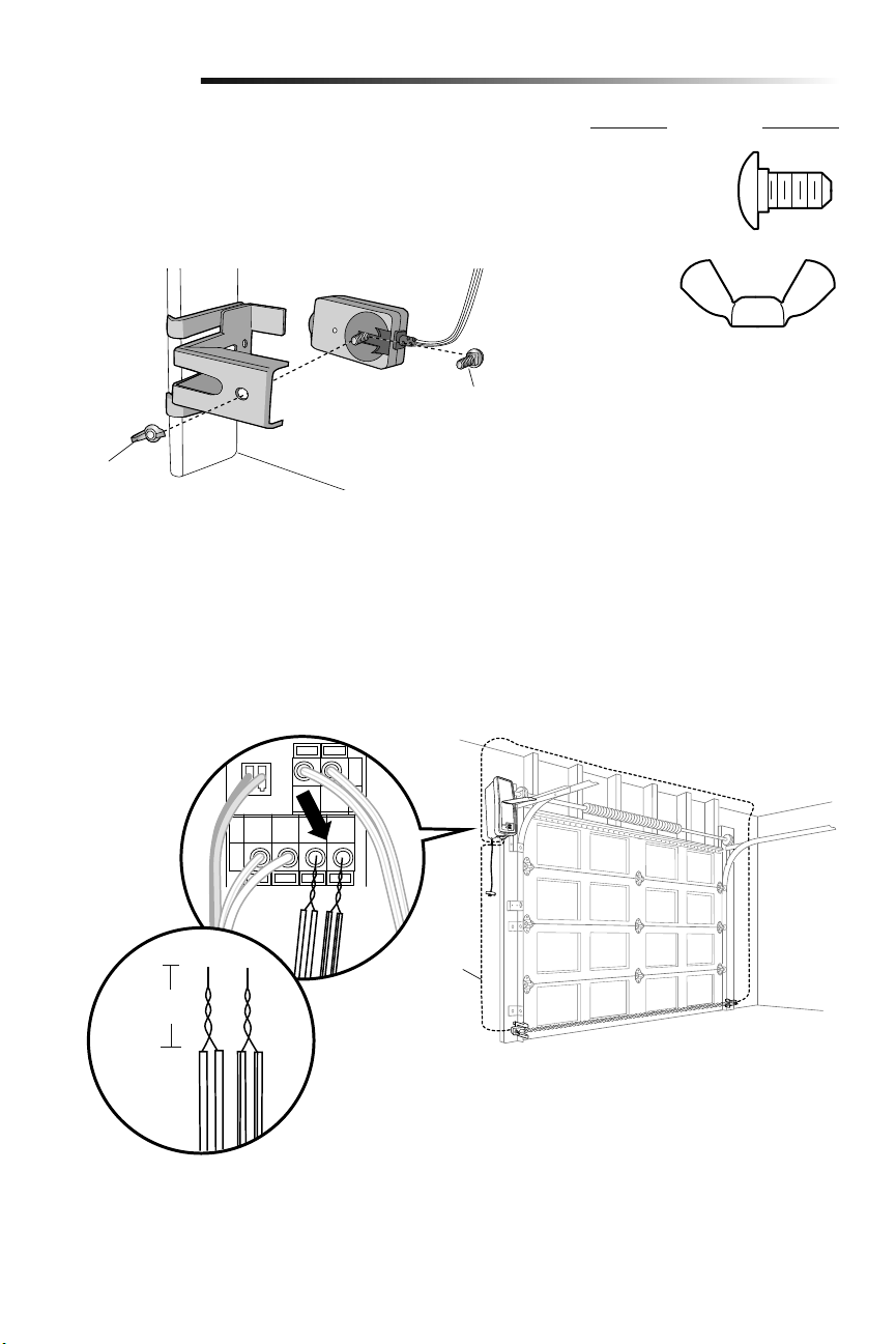
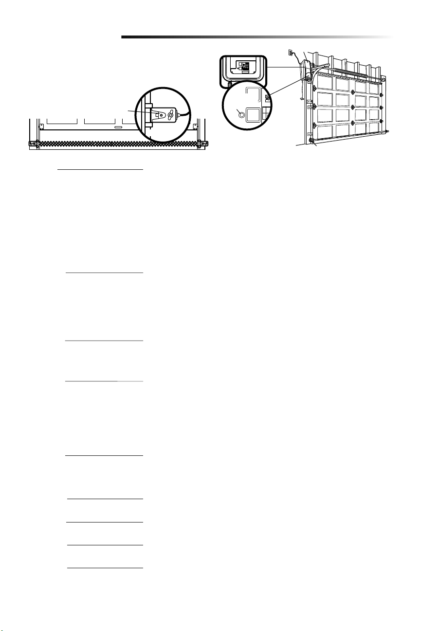
Attach the Cable Tension Monitor (Required)
4
NOTE: The cable tension monitor is shipped for left side installation. It is recommended
that the cable tension monitor be installed on the same side of the door as the garage
door opener. For right side installation, remove the snap-ring holding the roller in place
and reassemble it on the opposite side of the cable tension monitor.
1. Make sure the door cable is approximately 3/4" (19 mm) from the mounting surface.
Door adjustments or shimming may be required to achieve proper depth for the door
cable.
2.
Position the cable tension monitor as close to the drum as possible. Make sure cable
tension monitor is located over a wood support member and the roller is free from
any obstructions.
NOTE: There must be no obstructions in the installation area that prevent the cable
tension monitor from closing completely when slack is detected.
3. Mark and drill 3/16 inch pilot holes for screws (pilot holes are not required for
anchors).
NOTE: If the cable tension monitor cannot be mounted into wood with the screws
provided, it can be mounted into 1/2 inch (1 cm) or greater drywall using the drywall
anchors (2) and the #8 screws (2) provided in the hardware bag.
4. Attach the cable tension monitor to the wall using the hardware provided. Make sure
that the roller is on top of the cable.
5.
Run bell wire to garage door opener. Use insulated staples to secure wire.
6.
Connect bell wire to the green quick-connect terminals on the garage door opener
(polarity is not important).
NOTE: Cable must have tension through entire door travel. Make sure there is no
slack in cable on opposite side of garage door during normal operation. If slack
occurs during door travel, adjust cables as required.
Drum
Cable
To insert or
release wire,
push in tab with
screwdriver tip
(to cable tension monitor)
(to garage door opener)
WHT/
GRN
Wall
2"-6"
(5-15 cm)
Approx. 3/4" (19 mm)
Cable Tension
Monitor
Cable Tension
Monitor Roller
1/8"-1/4"
(3-6 mm)
Installation
The cable tension monitor MUST be
connected and properly installed before
the garage door opener will move in the
down direction.
The cable tension monitor detects ANY
slack that may occur in the cables and
will reverse the door, eliminating service
calls.
SIDE VIEW
Screws
#8-32x1" (2)
Drywall Anchor (screw-in) (2)
Drum
Cable Tension
Monitor Roller
Screw
14-10x2" (2)
11
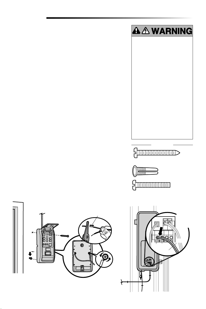
Install door control within sight of garage door, out of reach of small children at a
minimum height of 5 feet (1.5 m) above floors, landings, steps or any other adjacent
walking surface, and away from ALL moving parts of door.
For gang box installations it is not necessary to drill holes or install the drywall anchors.
Use the existing holes in the gang box.
NOTE: Due to power consumption this door control (Model 889LM) cannot be used in
conjunction with another wired door control connected to your garage door opener. If
an additional door control is needed, the wireless door control model 885LM can be
programmed to the door control (Model 889LM).
1. Strip 7/16" (11 mm) of insulation from one end of the wire and separate the wires.
2.
Connect wires to the door control. Make sure the polarity is correct.
• Red wire to the RED terminal.
• White wire to the WHT terminal.
3. Mark the location of the bottom mounting hole and drill a 5/32" (4 mm) hole.
4. Install the bottom screw, allowing 1/8" (3 mm) to protrude from the wall.
5. Position the bottom hole of the door control over the screw and slide down into
place.
6. Lift the push bar up and mark the top hole.
7. Remove the door control from the wall and drill a 5/32" (4 mm) hole for the top
screw.
8. Position the bottom hole of the door control over the screw and slide down into
place. Attach the top screw.
9. Run the white and red/white wire from the door control to the garage door opener.
Attach the wire to the wall and ceiling with the staples (not applicable for gang box
or pre-wired installations). Do not pierce the wire with the staple as this may cause
a short or an open circuit.
10. Strip 7/16" (11 mm) of insulation from the end of the wire near the garage door
opener. Connect bell wire to the quick-connect terminals on the garage door
opener: white to white and white/red to red.
11. Fasten the warning placard to the wall next to the door control.
NOTE: DO NOT connect the power and operate the garage door opener at this time. The
door will travel to the full open position but will not return to the close position until the
safety reversing sensors are connected and properly aligned. See page 13.
Install the Door Control (myQ Control Panel)
5
Installation
To prevent possible SERIOUS INJURY or
DEATH from electrocution:
• Be sure power is NOT connected
BEFORE installing door control.
• Connect ONLY to 7-28 VOLT low
voltage wires.
To prevent possible SERIOUS INJURY or
DEATH from a closing garage door:
• Install door control within sight of
garage door, out of reach of small
children at a minimum height of 5 feet
(1.5 m) above floors, landings, steps
or any other adjacent walking surface,
and away from ALL moving parts of
door.
• NEVER permit children to operate or
play with door control push buttons or
remote control transmitters.
• Activate door ONLY when it can be
seen clearly, is properly adjusted,
and there are no obstructions to door
travel.
• ALWAYS keep garage door in sight
until completely closed. NEVER permit
anyone to cross path of closing garage
door.
HARDWARE
Red White
WHT/RED
WHT
To insert or
release
wire, push
in tab with
screwdriver
tip
7/16" (11 mm)
Screw 6ABx1-1/4" (Standard installation) (2)
Screw 6-32x1"
(pre-wired) (2)
Drywall
Anchors (2)
(to garage door opener)
(to door control)
12
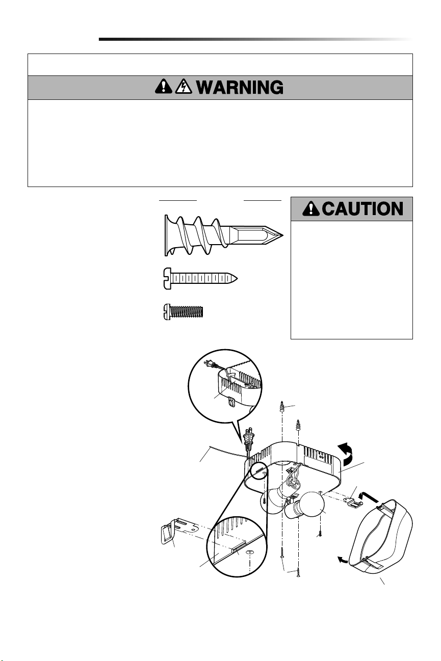
The remote light (garage door opener light)
is designed to plug directly into a standard
120V outlet. Select an appropriate location
on the ceiling to mount the light within 6
feet (1.83 m) of an electrical outlet so that
the cord and light are away from moving
parts.
1. Install the hinge and latch clips. Clips
slide in between the metal plate and
the plastic housing on each side of
the light base.
2. Install screws into the ceiling leaving
1/8 inch (3 mm) of the thread
exposed.
NOTE: If installing light on drywall
and a ceiling joist cannot be located,
use drywall anchors provided. No
pilot hole is required for drywall
anchors.
3. Determine the length of power cord
needed to reach the nearest outlet.
Wind any excess cord around cord
retainer on the top side of the light
base.
4.
Install the light base by pushing onto
the screws and turning the base
clockwise to lock the light in place.
5. Install two Type A19 incandescent or
compact fluorescent bulbs (100 watt
maximum per bulb, 200 watts total).
NOTE: Do not use LED bulbs as they
may reduce the range or performance
of your remote control(s).
6. Install the light lens by hooking one
end of the lens over the hinge and
pressing up on the other end to latch
into place.
7.
Plug in the light to outlet.
NOTE: Light will not operate until
the garage door opener is activated.
Multiple operators in the same garage
may cause interference between
lights. Program all lights to one
operator to avoid interference.
Install Remote Light
6
Installation
To prevent possible OVERHEATING of
the endpanel or light socket:
• DO NOT use short neck or specialty
light bulbs.
• DO NOT use halogen bulbs. Use
ONLY incandescent.
• DO NOT use bulbs larger than
100W.
• ONLY use A19 size bulbs.
To provide an adequate visual alert, the
garage door opener light bulb MUST be
a minimum of 40 Watt (or equivalent).
IMPORTANT INSTALLATION INSTRUCTIONS
To reduce the risk of SEVERE INJURY or DEATH:
1. This portable luminaire has a polarized plug (one blade
is wider than the other) as a feature to reduce the risk of
electric shock.
2. This plug will fit in a polarized outlet ONLY one way.
3. If the plug does not fit fully in the outlet, reverse the
plug.
4. If it still does not fit, contact a qualified electrician.
5. NEVER use with an extension cord unless plug can be
fully inserted.
6. DO NOT alter the plug.
7. Light is intended for ceiling mount and indoor
applications ONLY.
Latch Clip
Light Clip
Screw
Screws
Light Lens
Wall Anchor
Cord
Retainer
100 Watt
(max.)
Metal
Plate
Plastic
Housing
Hinge Clip
Drywall Anchor (screw-in) (2)
HARDWARE
Screw #4-20x7/16" (2)
Screw #6x1" (2)
Light Base
Antenna needs to be
fully exposed to prevent
intermittent light
behavior.
13
The safety reversing sensor must be connected and aligned correctly before the
garage door will move in the down direction. This is a required safety device and
cannot be disabled.
IMPORTANT INFORMATION ABOUT THE SAFETY REVERSING SENSOR
When properly connected and aligned, the safety reversing sensor will detect an obstacle
in the path of its electronic beam. The sending sensor (with an amber indicator light)
transmits an invisible light beam to the receiving sensor (with a green indicator light).
If an obstruction breaks the light beam while the door is closing, the door will stop and
reverse to full open position, and the opener lights will flash 10 times.
The sensors must be installed inside the garage so that the sending and receiving sensors
face each other across the door, no more than 6 inches (15 cm) above the floor. Either
can be installed on the left or right of the door as long as the sun never shines directly into
the receiving sensor lens.
The mounting brackets are designed to clip onto the track of sectional garage doors
without additional hardware.
If it is necessary to mount the sensors on the wall, the brackets must be securely fastened
to a solid surface such as the wall framing. Extension brackets (see accessories) are
available if needed. If installing in masonry construction, add a piece of wood at each
location to avoid drilling extra holes in masonry if repositioning is necessary.
The invisible light beam path must be unobstructed. No part of the garage door (door
tracks, springs, hinges, rollers or other hardware) may interrupt the beam while the door
is closing.
Be sure power is NOT connected to the
garage door opener BEFORE installing
the safety reversing sensor.
To prevent SERIOUS INJURY or
DEATH from a closing garage door:
• Correctly connect and align the
safety reversing sensor. This
required safety device MUST NOT
be disabled.
• Install the safety reversing sensor
so beam is NO HIGHER than 6" (15
cm) above garage floor.
Installation
Safety Reversing
Sensor
6" (15 cm) max.
above floor
Safety Reversing
Sensor
6" (15 cm) max.
above floor
Invisible Light
Beam Protection
Area
Install the Protector System
®
7
Facing the door from inside the garage.
14
OPTION C: Floor Installation
1. Use wood blocks or extension
brackets (see Accessories) to elevate
sensor brackets so the lenses will be
no higher than 6" (15 cm) above the
floor.
2. Carefully measure and place right and
left assemblies at the same distance
out from the wall. Be sure all door
hardware obstructions are cleared.
3. Fasten to the floor with concrete
anchors as shown.
Installation
Fasten Wood Block to Wall with
Lag Screws (not provided)
Attach with Concrete Anchors
(not provided)
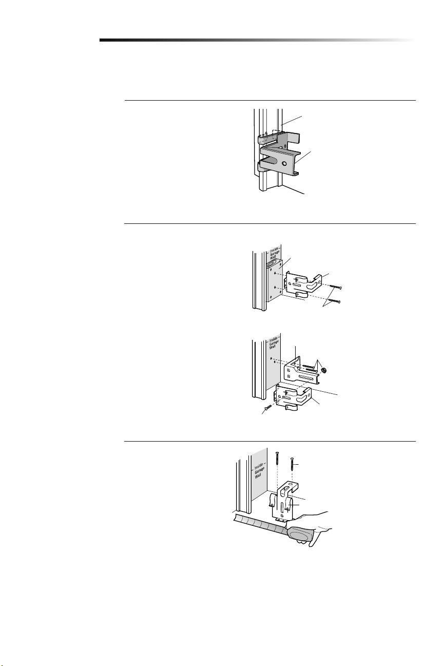
OPTION A: Track Installation
1. Slip the curved arms over the
rounded edge of each door track,
with the curved arms facing the door.
Snap into place against the side of the
track. It should lie flush, with the lip
hugging the back edge of the track, as
shown.
If your door track will not support the
bracket securely, wall installation is
recommended.
OPTION B: Wall Installation
1. Place the bracket against the wall
with curved arms facing the door. Be
sure there is enough clearance for the
sensor beam to be unobstructed.
2. If additional depth is needed, an
extension bracket (see Accessories)
or wood blocks can be used.
3. Use bracket mounting holes as a
template to locate and drill (2) 3/16"
diameter pilot holes on the wall at
each side of the door, no higher than
6" (15 cm) above the floor.
4. Attach brackets to wall with
lagscrews (notprovided).
If using extension brackets or wood blocks,
adjust right and left assemblies to the same
distance out from the mounting surface.
Make sure all door hardware obstructions
are cleared.
INSTALLING THE BRACKETS
Be sure power to the opener is disconnected. Install and align the brackets so the safety reversing sensors will face each other across
the garage door, with the beam no higher than 6" (15 cm) above the floor. Choose one of the following installations.
Door Track
Safety Reversing Sensor
Bracket
Safety Reversing Sensor Bracket
Lag Screws (not provided)
Safety Reversing Sensor Bracket
(Provided with Extension Bracket)
Extension Bracket (See Accessories)
Safety Reversing Sensor
Bracket
(Provided with
Extension Bracket)
15
Installation
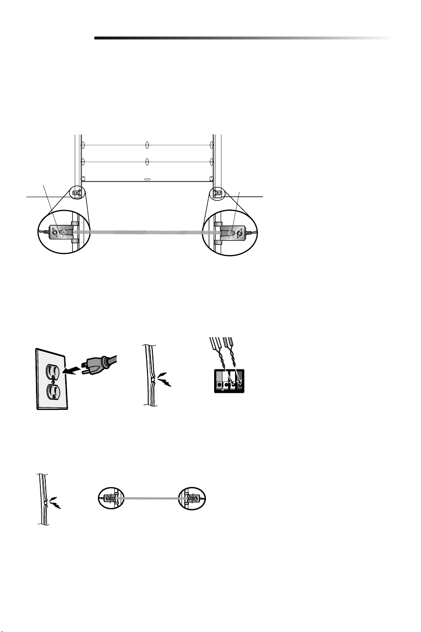
WIRE THE SAFETY REVERSING SENSORS
1. Run the wire from both sensors to the garage door opener. Attach the wire to the
wall and ceiling with the staples.
2. Strip 7/16 inch (11 mm) of insulation from each set of wires. Separate the wires.
Twist the white wires together. Twist the white/black wires together.
3. Insert the white wires into the white terminal on the garage door opener. Insert the
white/black wires into the grey terminal on the garage door opener. To insert or
remove the wires from the terminal, push in the tab with a screwdriver tip.
WHT/
BLK
Bell wire
WHT
MOUNTING THE SAFETY REVERSING SENSORS
1. Slide a 1/4"-20x1/2" carriage bolt head into the slot on each sensor.
2. Use wing nuts to fasten safety reversing sensors to brackets, with lenses pointing
toward each other across the door. Be sure the lens is not obstructed by a bracket
extension.
3. Finger tighten the wing nuts.
HARDWARE
Carriage Bolt
Wing Nut
Wing Nut
1/4"-20 (2)
Carriage Bolt
1/4"-20x1/2" (2)
7/16
(11 mm)
16
Ground
Tab
Green Ground
Screw
Ground Wire
Black Wire
From Power
Cord
White Wire
From Power
Cord
Flexible
Conduit
90˚
Connector
(Not
Provided)
Green Wire
White Wire
Black Wire
BACK VIEW
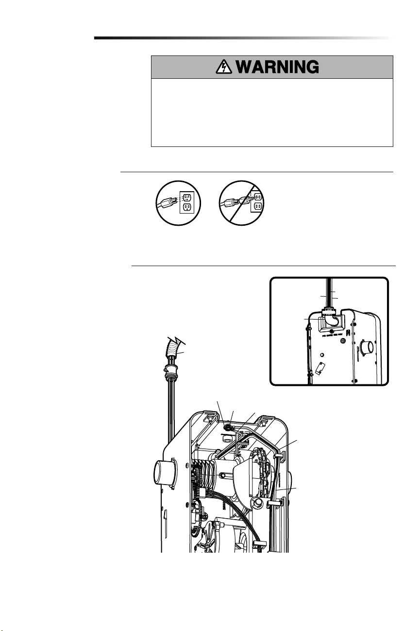
Connect Power
8
Installation
OPTION B: PERMANENT WIRING
CONNECTION
If permanent wiring is required by
your local code, refer to the following
procedure.
To make a permanent connection through
the 7/8 inch hole in the back of the garage
door opener (according to local code):
1.
Be sure power is NOT connected to
the opener, and disconnect power to
circuit.
2. Remove the garage door opener from
the torsion bar, remove cover screws
and set the cover aside.
3. Cut the line cord 6" (15.2 cm) above
the strain relief.
4. Squeeze the strain relief and push
into motor unit, then remove the
strain relief from the line cord.
5. Install a 90° conduit (not provided)
or flex cable adapter (not provided)
to the 7/8" hole. Reinstall garage door
opener to torsion bar.
6. Run wires through conduit, cut to
proper length and strip installation.
7. Strip 1/2" (1.3 cm) of insulation from
the existing black, white and green
wires.
8. Connect the line to the black wire and
neutral to the white wire with wire
nuts (not provided). Connect ground
wire to the green ground screw.
9. Properly secure wires under plastic
ties so that they do not come into
contact with moving parts.
10. Reinstall cover.
To avoid installation difficulties, do not
run the garage door opener at this time.
To reduce the risk of electric shock, your
garage door opener has a grounding type
plug with a third grounding pin. This plug
will only fit into a grounding type outlet. If
the plug doesn’t fit into the outlet you have,
contact a qualified electrician to install the
proper outlet.
There are two options for connecting
power:
OPTION A: TYPICAL WIRING
1. Plug in the garage door opener into a
grounded outlet.
2. DO NOT run garage door opener at
this time.
To prevent possible SERIOUS INJURY or DEATH from electrocution or fire:
• Be sure power is NOT connected to the opener, and disconnect power to circuit
BEFORE removing cover to establish permanent wiring connection.
• Garage door installation and wiring MUST be in compliance with ALL local electrical
and building codes.
• NEVER use an extension cord, 2-wire adapter or change plug in ANY way to make it
fit outlet. Be sure the opener is grounded.
RIGHT
IMPORTANT NOTE: The model 580LM
Alternate Power Supply may be installed
if an outlet is not located near the garage
door opener. myQ light controls will
continue to work however all other myQ
devices and TTC will not work if using the
Model 580LM Alternate Power Supply.
If you would like to use these features,
contact an electrician to install an outlet
near to the garage door opener.
WRONG
WRONGRIGHT
17
Receiving Sensor
Green LED
Sending Sensor
Amber LED
Installation
IF THE AMBER LED ON THE SENDING SENSOR IS NOT GLOWING:
• Make sure there is power to the garage door opener.
• Make sure the sensor wire is not shorted/broken.
• Make sure the sensor has been wired correctly: white wires to white terminal and
white/black wires to grey terminal.
If the receiving sensor is in direct
sunlight, switch it with sending
sensor so it is on the opposite side
of the door.
(invisible light beam)
ENSURE THE SAFETY REVERSING SENSORS ARE ALIGNED
The door will not close if the sensors have not been installed and aligned correctly.
When the light beam is obstructed or misaligned while the door is closing, the door will
reverse and the garage door opener lights will flash ten times. If the door is already open,
it will not close. The sensors can be aligned by loosening the wing nuts, aligning the
sensors, and tightening the wing nuts.
1.
Check to make sure the LEDs in both sensors are glowing steadily. The LEDs in both
sensors will glow steadily if they are aligned and wired correctly.
ENSURE THE DOOR CONTROL IS WIRED CORRECTLY
The yellow command LED and the red learn LED on the door control will blink quickly for
up to 5 minutes as the door control recharges. When the door control is operational, the
yellow command LED will glow steadily.
RED
WHITE
WHITE
GREY
IF THE GREEN LED ON THE RECEIVING SENSOR IS NOT GLOWING:
• Make sure the sensor wire is not shorted/broken.
• Make sure the sensors are aligned.
18
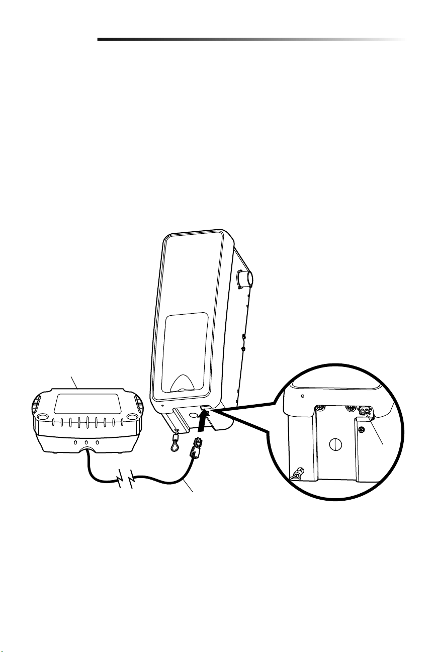
When in Battery Backup mode, wireless myQ devices and Timer-To-Close will be
disabled.
If the optional Battery Backup is part of this installation it should be installed at this time.
The Battery Backup can be mounted to either the ceiling or a wall within 3 feet (.9 m) of
the garage door opener.
1. Unplug the garage door opener.
2.
Position the Battery Backup on a structural support (ceiling joist or wall stud).
3. Attach the Battery Backup to the support with the 1-1/2 inch lag screws (2) provided.
There are mounting holes on either side of the Battery Backup.
4. Connect the Battery Backup cord into the connector on the bottom of the garage
door opener.
5. Follow all instructions included with the Battery Backup to test for proper operation.
Install the Battery Backup (optional)
9
Installation
Battery Backup Cord
475LM Battery Backup
Connector
19
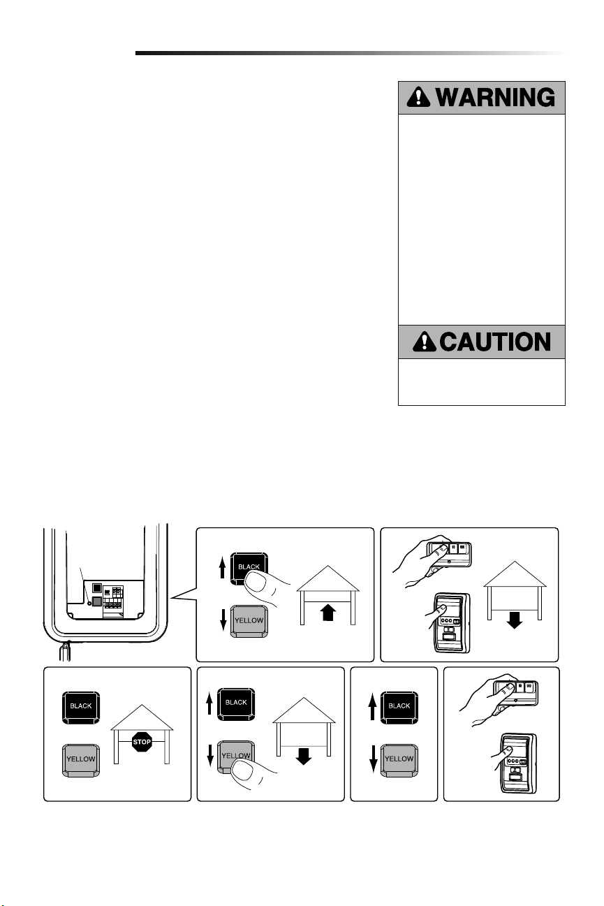
Adjust the position of the door by using the black and yellow buttons. Black moves the
door UP (open) and yellow moves the door DOWN (close).
NOTE: The yellow command LED and the red learn LED will blink quickly for up to
5 minutes as the control panel recharges. When the control panel is operational, the
yellow command LED will glow steadily.
SETTING THE UP POSITION:
1. Press and hold the black button until the LED starts flashing slowly, then release.
2. Push and hold the black button until the door reaches the desired UP (open)
position.
NOTE: Make sure the door opens high enough for your vehicle.
3. Push the door control or programmed remote control. This sets the UP (open) limit
and begins closing the door.
4.
Immediately when the door begins to close, press and release either the black or
yellow button. This will stop the door.
SETTING THE DOWN POSITION:
5. Push and hold the yellow button until the door reaches the desired DOWN (closed)
position.
6. Once the door is closed, if there appears to be too much pressure on the door, you
may toggle the door back and forth using the black and yellow buttons to reach the
desired closed position.
7. Push the door control or programmed remote control. This sets the DOWN (close)
limit and the door should open.
Proceed to Set the Force.
Travel limits regulate the points at which the door will stop when moving up or down.
Program the Travel Limits
Adjustment
1
2
Without a properly installed safety
reversal system, persons (particularly
small children) could be SERIOUSLY
INJURED or KILLED by a closing
garage door.
• NEVER learn forces or limits when
door is binding or sticking. Repair
door first.
• Incorrect adjustment of garage
door travel limits will interfere with
proper operation of safety reversal
system.
• After ANY adjustments are made,
the safety reversal system MUST
be tested. Door MUST reverse on
contact with 1-1/2" high (3.8 cm)
object (or 2x4 laid flat) on floor.
To prevent damage to vehicles, be
sure fully open door provides adequate
clearance.
1
LED
or
or
or
3
7456
20
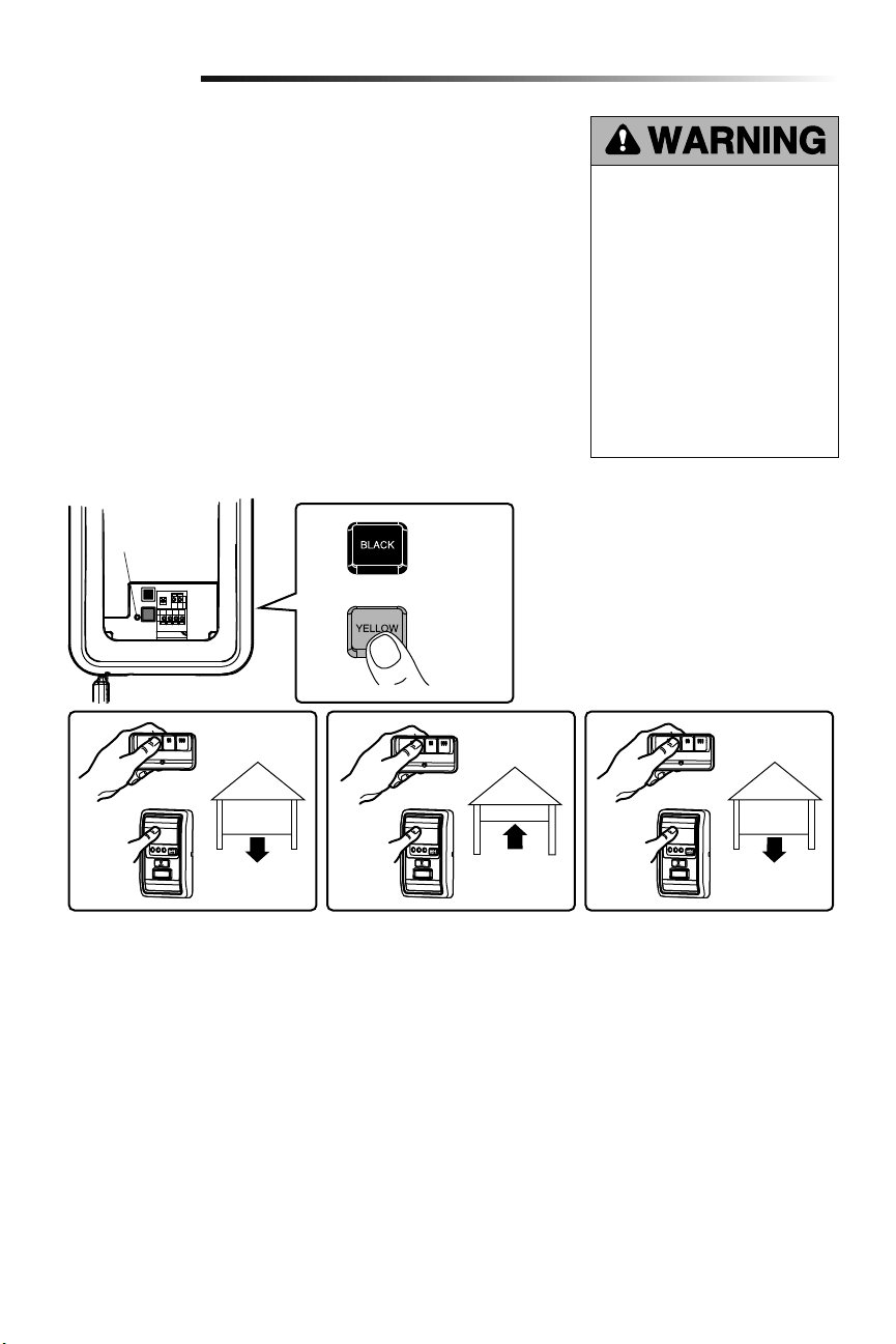
The force setting measures the amount of force required to open and close the door.
1. Push the yellow button twice to enter into the Force Adjustment Mode. The LED will
flash quickly.
2. Push the door control or programmed remote control. The door will close (DOWN).
3. Push the door control or programmed remote control again. The door will open (UP).
4. Push the door control or programmed remote control a third time to close the
door (DOWN).
The LED will stop flashing when the force has been programmed.
The door must travel through a complete cycle, up and down, in order for the force to be
set properly. If the garage door opener cannot open and close the door fully, inspect the
door to ensure that it is balanced properly and is not sticking or binding.
If the door is not stopping exactly where you would like it, repeat Program the
Travel Limits.
Set the Force
Without a properly installed safety
reversal system, persons (particularly
small children) could be SERIOUSLY
INJURED or KILLED by a closing
garage door.
• NEVER learn forces or limits when
door is binding or sticking. Repair
door first.
• Too much force on garage door
will interfere with proper operation
of safety reversal system.
• After ANY adjustments are made,
the safety reversal system MUST
be tested. Door MUST reverse on
contact with 1-1/2" high (3.8 cm)
object (or 2x4 laid flat) on floor.
2
Adjustment
1
LED
or or or
423
Push yellow
button twice to
enter garage
door opener
into Force
Adjustment
Mode

21
TEST
1. With the door fully open, place a 1-1/2 inch (3.8 cm) board (or a 2x4 laid flat) on the
floor, centered under the garage door.
2. Operate the door in the down direction. The door must reverse on striking the
obstruction. Upon successful safety reversal test proceed to Adjustment Step 4.
ADJUST
If the door stops on the obstruction, it is not traveling far enough in the down direction.
Complete Adjustment Steps 1 and 2 Program the Travel Limits and Set the Force.
Repeat the test.
When the door reverses on the 1-1/2 inch (3.8 cm) board (or 2x4 laid flat), remove the
obstruction and run the garage door opener through 3 or 4 complete travel cycles to
test adjustment.
If the garage door opener continues to fail the Safety Reverse Test, call for a trained door
systems technician.
IMPORTANT SAFETY CHECK:
Test the Safety Reverse System after:
• Each adjustment of limits, or force controls.
• Any repair to or adjustment of the garage door (including springs and hardware).
• Any repair to or buckling of the garage floor.
• Any repair to or adjustment of the opener.
Test the Safety Reversal System
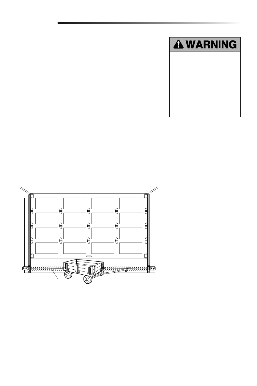
Test the Protector System
®
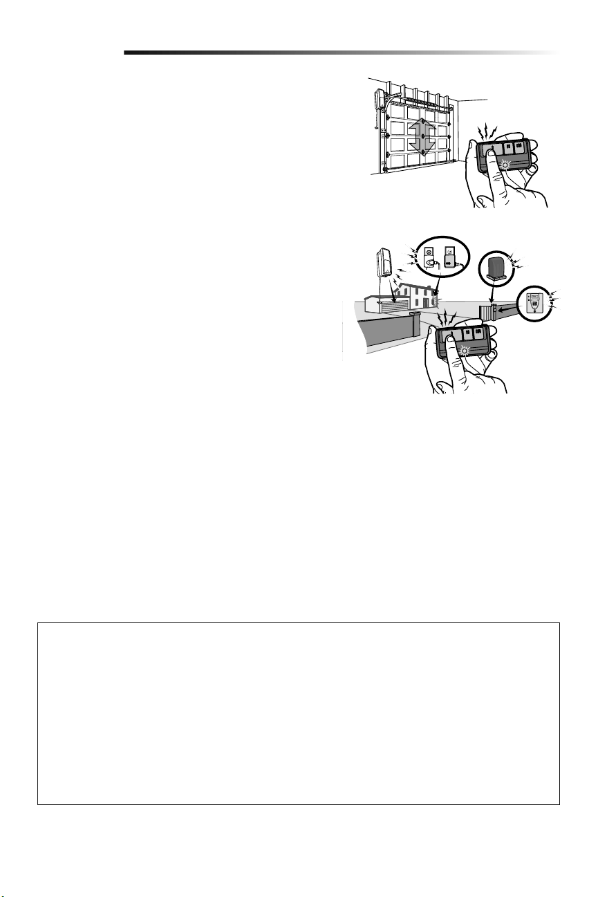
1. Press the remote control push button to open the door.
2. Place the opener carton in the path of the door.
3. Press the remote control push button to close the door. The door will not move
more than an inch (2.5 cm), and the opener lights will flash.
The garage door opener will not close from a remote if the indicator light in either sensor
is off(alerting you to the fact that the sensor is misalignedor obstructed).
If the garage door opener closes the door when the safety reversing sensor is
obstructed, do not operate the door. Call for a trained door systems technician.
Without a properly installed safety
reversal system, persons (particularly
small children) could be SERIOUSLY
INJURED or KILLED by a closing
garage door.
• Safety reversal system MUST be
tested every month.
• If one control (force or travel limits)
is adjusted, the other control may
also need adjustment.
• After ANY adjustments are made,
the safety reversal system MUST
be tested. Door MUST reverse on
contact with 1-1/2" (3.8 cm) high
object (or 2x4 laid flat) on the floor.
Without a properly installed safety
reversing sensor, persons (particularly
small children) could be SERIOUSLY
INJURED or KILLED by a closing
garage door.
3
4
Adjustment
Safety Reversing Sensor
Safety Reversing Sensor
1-1/2" (3.8 cm) board
(or a 2x4 laid flat)
22
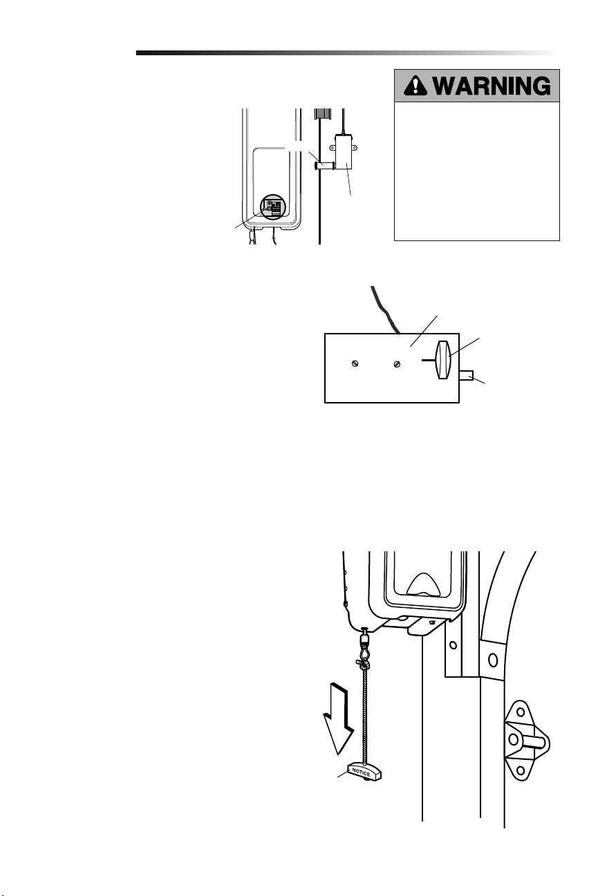
1. With the door fully closed, push on
the front of the cable tension monitor.
A click should be heard. If there is
no click, the roller may be hitting the
jamb and not allowing the switch to
detect slack in the cable. Make sure
the cable tension monitor is mounted
flush with the wall and the roller is
free from any obstructions.
If your cable tension monitor has been
activated the LED on the garage door
opener will blink 9 times.
1. With the door fully closed, the power
door lock bolt should be protruding
through the track.
2. Operate the door in the open direction.
The power door lock should retract
before the door begins to move.
3. Operate the door in the down direction.
When the door reaches the fully closed
position, the power door lock should
automatically activate to secure the door.
NOTE: If the power door lock does
not function, the lock can be manually
released by sliding the manual release
handle to the open position.
Disengage door lock before proceeding. The
door should be fully closed if possible. Pull
down on the emergency release handle until
a click noise is heard from the garage door
opener and lift the door manually.
To reconnect the door to the garage door
opener, pull the emergency release handle
straight down a second time until a click noise
is heard from the garage door opener. The
door will reconnect on the next UP or DOWN
operation.
Test the emergency release:
1. Make sure the garage door is closed.
2. Pull the emergency release handle. The
garage door should then be able to be
opened manually.
3. Return the door to the closed position.
4. Pull the emergency handle a second
time.
5. Reconnect the door to the garage door
opener.
Test Cable Tension Monitor
Test Power Door Lock
To Open the Door Manually
5
6
7
Adjustment
To prevent possible SERIOUS INJURY
or DEATH from a falling garage door:
• If possible, use emergency release
handle to disengage door ONLY when
garage door is CLOSED. Weak or
broken springs or unbalanced door
could result in an open door falling
rapidly and/or unexpectedly.
• NEVER use emergency release handle
unless garage doorway is clear of
persons and obstructions.
Power Door Lock
Manual Release
Lock Bolt
“Locked”
Emergency
Release Handle
LED
Cable Tension
Monitor
Roller

23
Operation
IMPORTANT SAFETY INSTRUCTIONS
To reduce the risk of
SEVERE INJURY or DEATH:
1. Read and follow ALL warnings and instructions.
2. ALWAYS keep remote controls out of reach of children.
NEVER permit children to operate or play with door control
push buttons or remote controls.
3. ONLY activate door when it can be seen clearly, it is properly
adjusted and there are no obstructions to door travel.
4. ALWAYS keep garage door in sight and away from people
and objects until completely closed. NO ONE SHOULD
CROSS THE PATH OF THE MOVING DOOR.
5. NO ONE SHOULD GO UNDER A STOPPED, PARTIALLY
OPENED DOOR.
6. If possible, use emergency release handle to disengage
door ONLY when door is CLOSED. Use caution when using
this release with the door open. Weak or broken springs or
unbalanced door could result in an open door falling rapidly
and/or unexpectedly and increasing the risk of SEVERE
INJURY or DEATH.
7. NEVER use emergency release handle unless doorway is
clear of persons and obstructions.
8. After ANY adjustments are made, the safety reversal system
MUST be tested. Failure to adjust the garage door opener
properly may cause SEVERE INJURY or DEATH.
9. Safety reversal system MUST be tested every month. Door
MUST reverse on contact with 1-1/2" (3.8 cm) high object
(or a 2x4 laid flat) on the floor. Failure to adjust the garage
door opener properly may cause SEVERE INJURY or
DEATH.
10. ALWAYS KEEP DOOR PROPERLY BALANCED (see page4).
An improperly balanced door may NOT reverse when
required and could result in SEVERE INJURY or DEATH.
11. ALL repairs to cables, spring assemblies and other
hardware, ALL of which are under EXTREME tension, MUST
be made by a trained door systems technician.
12. To avoid SERIOUS PERSONAL INJURY or DEATH from
electrocution, disconnect ALL electric and battery power
BEFORE performing ANY service or maintenance.
13. This operator system is equipped with an unattended
operation feature. The door could move unexpectedly. NO
ONE SHOULD CROSS THE PATH OF THE MOVING DOOR.
14.
SAVE THESE INSTRUCTIONS.
Your garage door opener has already been
programmed at the factory to operate
with your remote control, which changes
with each use, randomly accessing over
100 billion new codes. myQ technology
uses a 900MHz signal to provide two-way
communication between the garage door
opener and myQ enabled accessories.
When programmed to the LiftMaster
®
Internet Gateway you can monitor and
control your garage door from any internet
enabled computer or smartphone. You may
program up to 12 Security+ 2.0
®
remote
controls, 2 Security+ 2.0
®
keyless entries
and a combination of 16 myQ accessories
to the myQ control panel.
The garage door opener can be activated
through a wall-mounted door control,
remote control, wireless keyless entry or
myQ accessory. When the door is closed
and the garage door opener is activated
the door will open. If the door senses an
obstruction or is interrupted while opening
the door will stop. When the door is in any
position other than closed and the garage
door opener is activated the door will
close. If the garage door opener senses
an obstruction while closing, the door will
Using Your Garage Door Opener
reverse. If the obstruction interrupts the
sensor beam the garage door opener lights
will blink 10 times. However, you can close
the door if you hold the button on the door
control or keyless entry until the door is
fully closed. The safety reversing sensors
do not affect the opening cycle. The safety
reversing sensor must be connected and
aligned correctly before the garage door
opener will move in the down direction.
The garage door opener lights will turn on
when the garage door opener is activated.
They will turn off automatically after 4-1/2
minutes or provide constant light when the
Light feature on the myQ Control Panel is
activated. Bulb size is A19. Bulb power is
100 watts maximum.
Light feature: Lights will also turn on when
someone walks through the open garage
door. With a myQ Control Panel, this
feature may be turned off as follows: With
the garage door opener lights off, press
and hold the light button for 10 seconds,
until the light goes on, then off again. To
restore this feature, start with the garage
door opener lights on, then press and hold
the light button for 10 seconds until the
light goes off, then on again.
TIMER-TO-CLOSE (TTC)
The TTC feature automatically closes the
door after a specified time period that
can be adjusted using a TTC enabled
door control. Prior to and during the door
closing the garage door opener lights will
flash and the garage door opener will beep.
BATTERY BACKUP*
The battery backup system allows access
in and out of your garage, even when the
power is out. When the garage door opener
is operating on battery power, the garage
door opener will run slower, the light will
not function, the Battery Status LED will
glow solid orange, and a beep will sound
approximately every 2 seconds.
* If applicable.
24
Once the garage door opener is activated
the lights will turn off after the specified
period of time (the factory setting is 4-1/2
minutes). The LIGHT button will not control
the lights when the door is in motion.
To change the amount of time the garage
door opener lights will stay on:
Press and hold the LOCK button until the
garage door opener lights flash. The time
interval is indicated by the number of
flashes.
NUMBER OF
TIMES GARAGE
DOOR OPENER
LIGHTS FLASH
TIME THE
GARAGE DOOR
OPENER LIGHT
STAYS ON
1 1 ½ Minutes
2 2 ½ Minutes
3 3 ½ Minutes
4 4 ½ Minutes
Light Feature
The lights will turn on when someone
enters through the open garage door and
the safety reversing sensor infrared beam
is broken.
Activate:
Start with the garage door opener
lights on. Press and hold the LIGHT
button until the garage door opener
lights turn off, then on again.*
Deactivate:
Press and hold the LIGHT button until
the garage door opener lights turn on,
then off again.*
* Approximately 10 seconds
Operation
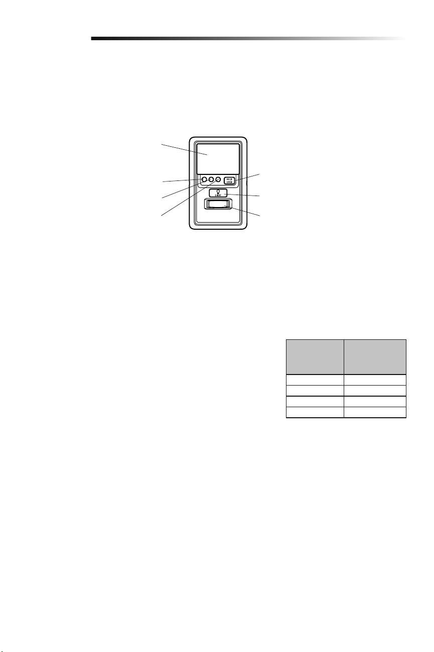
PUSH BAR
Press the push bar to open/close the door.
LOCK
Designed to prevent operation of the door
from hand-held remote controls. However,
the door will open and close from the
Door Control, the Outdoor Key Switch, the
Keyless Entry Accessories and LiftMaster
®
Internet Gateway.
Activate:
Press and hold the LOCK button for 2
seconds. The command LED will flash
as long as the lock feature is activated
and your handheld remote control will
not operate your door at this time.
Deactivate:
Press and hold the LOCK button again
for 2 seconds. The command LED will
stop flashing and normal operation
will resume.
MOTION SENSOR
This feature will automatically turn on the
garage door opener lights when motion is
sensed. The lights will come on for 4-1/2
minutes, then shut off.
Activate/Deactivate:
Slide the motion sensor switch ON or
OFF.
TIMER-TO-CLOSE (TTC)
The TTC feature automatically closes the
door after a specified time period (1, 5,
or 10 minutes). Once the TTC has been
set and the door is open, the LED for
the selected close interval will blink and
begin to count down to close the door.
The control panel will beep and the garage
door opener lights will flash before closing
the door.
Using the Door Control (myQ Control Panel)
NOTE: Due to power consumption this door control (Model 889LM) cannot be used in conjunction with another wired door control
connected to your garage door opener. If an additional door control is needed, the wireless door control model 885LM can be
programmed to the door control (Model 889LM). To program the 885LM to the myQ Control Panel, follow the remote control
programming steps.
NOTE: myQ light controls will continue to work however all other myQ devices and TTC will not work if using the Model 580LM Alternate
Power Supply or when in Battery Backup mode.
The TTC feature will deactivate if the garage
door encounters an obstruction twice; or
the safety reversing sensors are incorrectly
installed. The garage door will reverse open
and WILL NOT close until the obstructions
are clear or the safety reversing sensors
are correctly installed. When the
obstruction has been cleared or the safety
reversing sensors have been aligned,
the door will close when the garage door
opener is activated.
Activate:
Press and hold the ON button until
one of the TTC LEDs light up. Then
press the ON button again to cycle
through the time interval options (the
corresponding TTC LED will light
for each time interval). The garage
door opener light bulbs will blink as
confirmation.
Deactivate:
Press and hold the OFF button until
all TTC LEDs turn off and a beep is
heard from the control panel.
To suspend the TTC:
To suspend the TTC and temporarily
hold the door open, press and release
the HOLD OPEN button (the HOLD
OPEN LED will turn solid). The TTC
will remain suspended until the HOLD
OPEN button is pressed again or the
garage door opener is activated from
another device (door control, remote
control, keyless entry, etc.).
LIGHTS
Press the LIGHT button to turn the garage
door opener lights on or off. When the
lights are turned on they will stay on until
the LIGHT button is pressed again, or
until the garage door opener is activated.
LIGHT Button
HOLD OPEN Button for the Timer-
To-Close (TTC)
Motion Sensor
Push Bar
1 Minute TTC LED
5 Minute TTC LED
10 Minute TTC LED
25
Operation
Using the Remote Control
Press and hold the button down until the door or gate starts to move.
The remote control will operate from up to 3 car lengths away on typical
installations. Installations and conditions vary, contact an installing dealer for
more information.
3-Button Remote Controls
Additional buttons on the remote control can be programmed to operate
up to 3 devices such as additional garage door openers, light controls, gate
operators or access control systems.
NOTICE: This device complies with Part 15 of the FCC rules and Industry Canada’s license-exempt RSSs. Operation is subject to the following two
conditions: (1) this device may not cause harmful interference, and (2) this device must accept any interference received, including interference that may
cause undesired operation.
Any changes or modifications not expressly approved by the party responsible for compliance could void the user’s authority to operate the equipment.
This device must be installed to ensure a minimum 20 cm (8 in.) distance is maintained between users/bystanders and device.
This device has been tested and found to comply with the limits for a Class B digital device, pursuant to part 15 of the FCC rules and Industry Canada
ICES standard. These limits are designed to provide reasonable protection against harmful interference in a residential installation. This equipment
generates, uses and can radiate radio frequency energy and, if not installed and used in accordance with the instructions, may cause harmful interference
to radio communications. However, there is no guarantee that interference will not occur in a particular installation. If this equipment does cause harmful
interference to radio or television reception, which can be determined by turning the equipment off and on, the user is encouraged to try to correct the
interference by one or more of the following measures:
• Reorient or relocate the receiving antenna.
• Increase the separation between the equipment and receiver.
• Connect the equipment into an outlet on a circuit different from that to which the receiver is connected.
• Consult the dealer or an experienced radio/TV technician for help.
26
Programming
Your hand-held remote control (model 893MAX) has already programmed to the door control (myQ Control Panel) at the factory. Below
are instructions for programming additional remote controls, keyless entries, and myQ enabled accessories to the door control.
NOTE: Use the learn button on the door control to program all accessories. The yellow learn button on the garage door opener will NOT
program accessories.
PIN
?
?
??
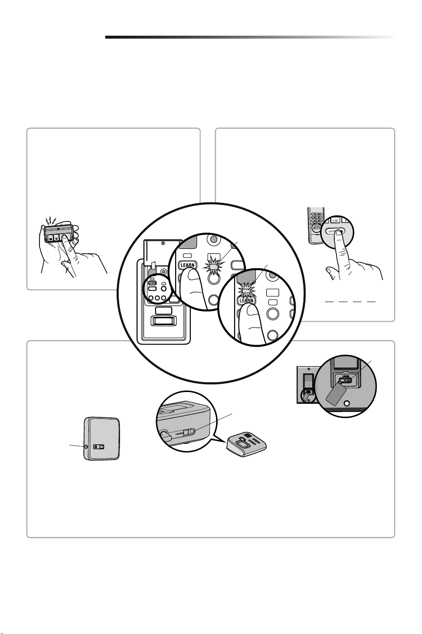
REMOTE CONTROL
1. Press the myQ Control Panel LEARN button twice,
the red learn LED will turn on.
2. Press the button on the remote control that you
wish to operate your garage door.
3. The garage door opener lights will flash (or two
clicks will be heard) when the code has been
programmed.
1. Press the myQ Control Panel LEARN button twice, the
red learn LED will turn on.
2. Enter a 4-digit personal identification number (PIN) of
your choice on the keyless entry keypad. Then press
the ENTER button.
3. The garage door opener lights will flash (or two clicks
will be heard) when the code has been programmed.
KEYLESS ENTRY
LEARN
Button
LEARN
Button
Model 825LM - Remote Light Control
Light module can be synchronized with
the garage door opener light bulbs.
Model 823LM - Remote Light Switch
Light module can be synchronized with
the garage door opener light bulbs.
LEARN
Button
Model 829LM - Garage Door and Gate
Monitor
Indicates the status of your garage door
from inside the home and allows you to
close an open garage door from inside the
house.
myQ ENABLED ACCESSORIES
1. Press the myQ Control Panel
LEARN button twice, the red learn
LED will turn on.
2. Press the LEARN button on the
myQ device.*
* myQ accessories may be programmed
to the LiftMaster
®
Internet Gateway
(Model 828LM) or the myQ control
panel. For instructions on
programming to the LiftMaster
®
Internet Gateway refer to the manual.
Command
LED (yellow)
Learn LED
(Red)
To Add a Remote Control, Keyless Entry, or myQ Enabled Accessories using the
Door Control (myQ Control Panel)
27
Programming
LiftMaster
®
Internet Gateway (Not Provided)
The LiftMaster
®
Internet Gateway gives you control of your garage door from your internet
connected computer or mobile device.
To program your myQ Control Panel to the LiftMaster
®
Internet Gateway:
1. Download the myQ App.
2. Set up an account and connect.
3. Select “Internet Gateway” and follow the instructions in the app. IMPORTANT: When
instructed to press the “Learn” Button, this will be located on the myQ Control
Panel, and the “Learn” button must be pressed 2 times.
IMPORTANT NOTE: Model 580LM Alternate Power Supply may be installed if an outlet is
not located near the garage door opener. myQ light controls will continue to work however
all other myQ devices (LiftMaster
®
Internet Gateway) and TTC WILL NOT work if using the
Model 580LM Alternate Power Supply. If you would like to use these features, contact an
electrician to install an outlet near the garage door opener.
Model 828LM
LiftMaster
®
Internet
Gateway
To Erase All Codes From the Door Control (myQ Control
Panel) Memory
Erase all remote controls and keyless entries:
1. Press and hold the LEARN button on the control panel until the red learn LED goes
out (approximately 6 seconds). All remote control and keyless entry codes are now
erased. Reprogram any compatible accessory you wish to use.
Erase all devices (including myQ enabled accessories):
1. Press and hold the LEARN button on the control panel until the red learn LED goes out
(approximately 6 seconds).
2. Immediately press and hold the LEARN button again until the red learn LED goes out.
All codes are now erased. Reprogram any compatible accessory you wish to use.
Red Learn LED
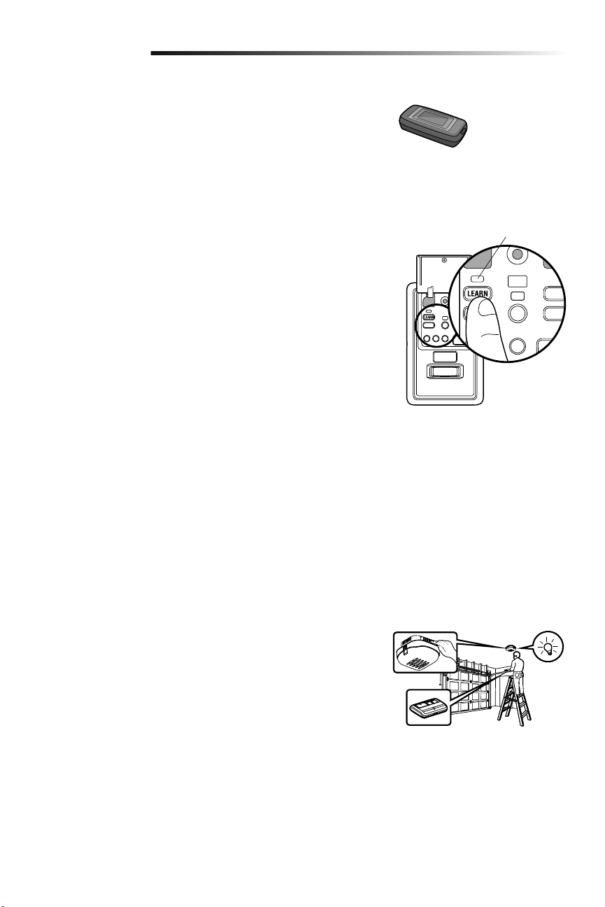
Reprogramming Remote Light or Additional Light
Your garage door opener remote light has already been programmed at the factory to
operate with your opener. Any additional or replacement remote lights will need to be
programmed.
1. Press the LEARN button on the light until the LED comes ON.
2. Activate the garage door opener using the hand-held remote, door control, or
keyless entry.
3. The code has been programmed when the remote light comes on.
28
Programming
Additional Programming for the Keyless Entry (Not Provided)
TO CHANGE AN EXISTING, KNOWN PIN
If the existing PIN is known, it may be changed by one person without using a ladder.
1. Press the four buttons for the present PIN, then press and hold the # button. Release the # button.
2. Press the new 4-digit PIN you have chosen, then pressEnter.
Test by pressing the new PIN, then press Enter. The door should move.
TO SET A TEMPORARY PIN
You may authorize access by visitors or service people with a temporary 4-digit PIN. After a programmed number of hours or number of
accesses, this temporary PIN expires and will no longer open the door. It can be used to close the door even after it has expired. To set a
temporary PIN:
1. Press the four buttons for your personal entry PIN (not the last temporary PIN), then press and hold the @ button. Release the
button.
2. Press the temporary 4-digit PIN you have chosen, then press Enter.
3. To set the number of hours this temporary PIN will work, press the number of hours (up to 255), then press @.
OR
3. To set the number of times this temporary PIN will open door, press the number of times (up to 255), then press #.
Test by pressing the four buttons for the temporary PIN, then press Enter. The door should move. If the temporary PIN was set to a
certain number of openings, remember that the test has used up one opening. To clear the temporary password, repeat steps 1-3, setting
the number of hours or times to 0 in step 3.
ONE BUTTON CLOSE:
The garage door opener can be closed by pressing only the ENTER button if the one button close feature has been activated. This feature
has been activated at the factory. To activate or deactivate this feature press and hold buttons 1 and 9 for 10 seconds. The keypad will
blink twice when the one button close is active. The keypad will blink four times when one button close is deactivated.
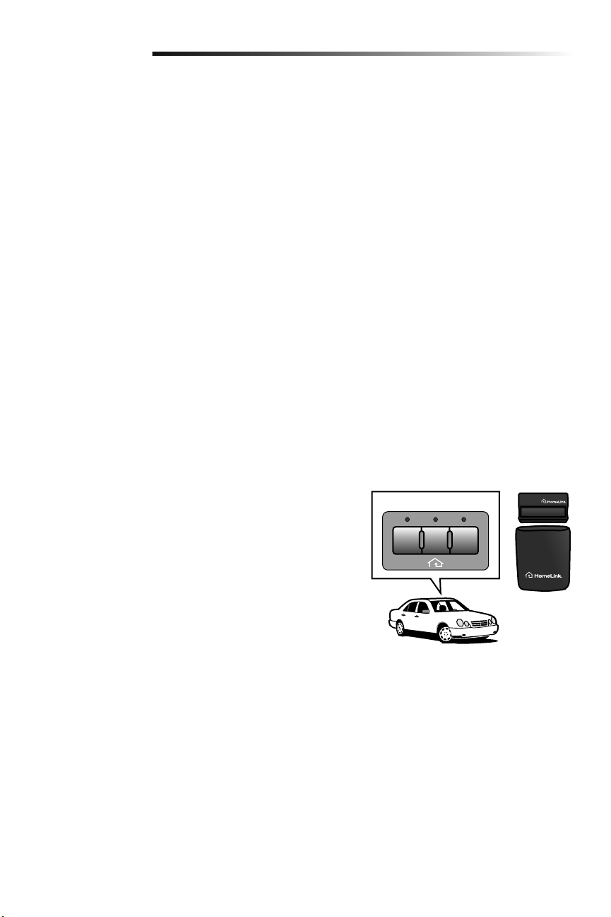
HomeLink
®
In the rare case the HomeLink system does not program with the Security+ 2.0
Garage door opener, install a repeater kit. Refer to HomeLink instructions below.
HomeLink is the in-vehicle system. The image used is for reference only and your
product may look different.
WHEN TO INSTALL A HOMELINK REPEATER KIT
All 2006 and Older vehicles – A repeater kit is required and must be purchased by
the homeowner.
All 2007 and Newer vehicles – Program the HomeLink according to the vehicle
instructions. If after ONE attempt to program the HomeLink to the garage door
opener and you are unsuccessful, install a repeater.
HOW TO ORDER
Order the HomeLink repeater kit from an installer or call 1-800-355-3515. To
program the HomeLink repeater kit, refer to the instructions provided in the kit or visit:
http://www.homelink.com/program.
INSTALLATION QUICK FACTS
• Only one repeater kit is required per home.
• Use different HomeLink buttons in vehicle if programming multiple cars, button 1
first car, button 2 second car… etc.
• HomeLink remote is NOT a garage door opener.
• If you are using the HomeLink repeater with a garage door opener that has a
battery backup system, ensure your original garage door opener remote control is
programmed to the garage door opener and place it in your glove box for use in the
event of a power outage.
• The remote included in this repeater kit MUST be kept for future programming (new
vehicle, new garage door opener etc).
IIIIII
HomeLink
®
Repeater Kit
29
Maintenance
MAINTENANCE SCHEDULE
Once a Month
• Manually operate door. If it is unbalanced or binding, call a trained door systems
technician.
• Check to be sure door opens and closes fully. Adjust limits and/or force if necessary
(see Adjustment Steps 1 and 2).
• Repeat the safety reverse test. Make any necessary adjustments (see Adjustment
Step 3).
Once a Year
• Oil door rollers, bearings and hinges. The garage door opener does not require
additional lubrication. Do not grease the door tracks.
Care of Your Garage Door Opener
To prevent possible SERIOUS INJURY
or DEATH:
• NEVER allow small children near
batteries.
• If battery is swallowed, immediately
notify doctor.
To reduce risk of fire, explosion or
chemical burn:
• Replace ONLY with 3V CR2032
coin batteries.
• DO NOT recharge, disassemble,
heat above 212° F (100° C) or
incinerate.
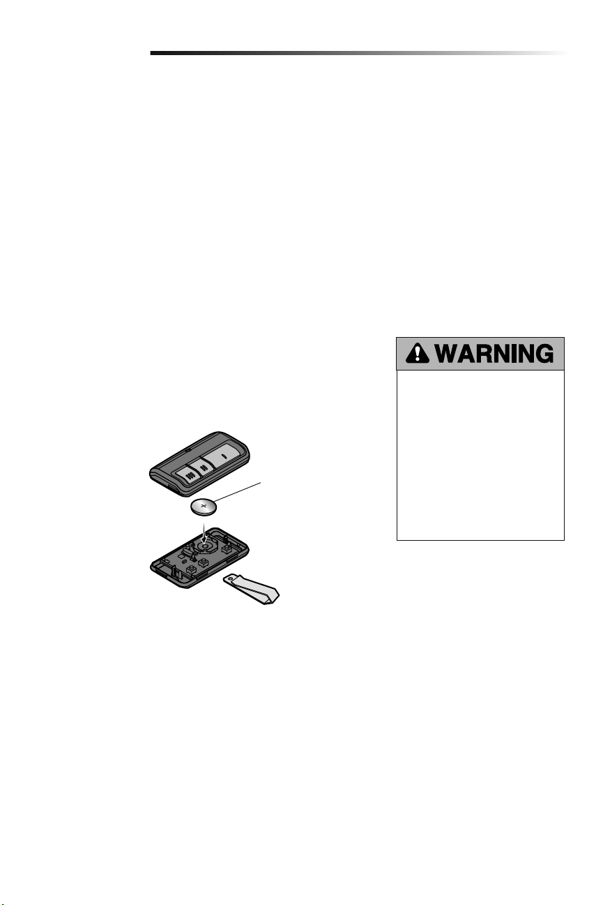
THE REMOTE CONTROL BATTERY
The LED(s) on your remote control will stop flashing when the battery is low and needs
to be replaced. To replace battery, open the case as shown. Insert battery positive side up
(+). Replace the battery with only 3V CR2032 coin cell batteries. Dispose of old battery
properly.
1
2
3
3V CR2032
Pry open the case first
in the middle (1), then at
each side (2 and 3) with
the visor clip.
30
Troubleshooting
Your garage door opener is programmed with self-diagnostic
capabilities. The diagnostic LED will flash a number of times, then
pause, signifying it has found a potential issue.
Consult Diagnostic Chart below.
Diagnostic Chart
SYMPTOM: One or both of the Indicator lights on the safety sensors do not glow
steady.
• Inspect sensor wires for a short (staple in wire), correct wiring polarity (black/white
wires reversed), broken or disconnected wires, replace/attach as needed.
• Disconnect all wires from back of garage door opener.
• Remove sensors from brackets and shorten sensor wires to 1-2 ft. (30-60 cm) from
back each of sensor.
• Reattach sending sensor to garage door opener using shortened wires. If sending
sensor indicator light glows steadily, attach the receiving sensor.
• Align sensors, if the indicator lights glow replace the wires for the sensors. If the
sensor indicator lights do not light, replace the safety reversing sensors.
SYMPTOM: The door doesn't activate from the door control.
• Inspect door control/wires for a short (staple in wire), replace as needed.
• Disconnect wires at door control, touch wires together. If garage door opener
activates, replace door control.
• If garage door opener does not activate, disconnect door control wires from garage
door opener. Momentarily short across red and white terminals with jumper wire. If
garage door opener activates, replace door control wires.
SYMPTOM: Sending indicator light glows steadily, receiving indicator light is dim or
flashing.
• Realign receiving sensor, clean lens and secure brackets.
• Verify door track is firmly secured to wall and does not move.
SYMPTOM: Door travels 2-3 inches and stops.
• Reprogram limits and forces. See Adjustment section.
• If the motor unit continues to travel 2-3 inches, check the travel module connection
or replace the travel module.
SYMPTOM: No movement, motor runs 2-3 seconds.
• Reconnect the emergency release.
• Motor may need to be replaced.
SYMPTOM: Door stops and reverses while closing.
• Check for possible door obstructions and remove.
• Check that the cable tension monitor is properly connected to the opener.
• Replace the cable tension monitor.
SYMPTOM: Door stops while opening.
• Reprogram limits and forces. See Adjustment section.
SYMPTOM: Door stops and reverses while closing.
• Reprogram limits and forces. See Adjustment section.
SYMPTOM: Door stops and reverses while closing.
• Garage door opener will try to compensate three times before turning to a 10 Flash.
SYMPTOM: Door stops while opening.
• Garage door opener will try to compensate three times before turning to a 11 Flash.
1 FLASH
Safety reversing sensors wire open
(broken or disconnected)
2 FLASHES
Safety reversing sensors wire shorted or
black/white wire reversed
3 FLASHES
Door control or wire shorted
4 FLASHES
Safety reversing sensors slightly
misaligned (dim or flashing LED)
5 FLASHES
Motor RPM is not recognized
9 FLASHES
Cable tension monitor reversal
10 FLASHES
Limits and forces need reprogramming
11 FLASHES
Limits and forces need reprogramming
12 FLASHES
Attempting to compensate
13 FLASHES
Attempting to compensate
OR
Safety Reversing Sensor
Garage Door Opener
Diagnostic
LED
Installed
Safety Reversing
Sensor
Installed Safety Reversing Sensor

31
Troubleshooting
The garage door doesn't operate from the myQ Home Control App or website.
• When using Model 580LM Alternate Power Supply or when in Battery Backup mode, the LiftMaster
®
Internet Gateway will not
activate the garage door through the myQ Home Control App. If you wish to use the LiftMaster
®
Internet Gateway with your garage
door opener, please contact your local electrician to wire an outlet next to the garage door opener.
The garage door opener doesn't operate from either the Door Control or the remote control:
• Does the garage door opener have electric power? Plug a lamp into the outlet. If it doesn't light, check the fuse box or the circuit
breaker. (Some outlets are controlled by a wall switch.)
• Have you disabled all door locks? Review installation instruction warnings on page 7.
• Is there a build-up of ice or snow under the door? The door may be frozen to the ground. Remove any restriction.
• The garage door spring may be broken. Have it replaced (see page 3 for reference).
• If the yellow command LED does not turn on, reverse the wires connected to the RED and WHT terminals of the control panel.
Replace wire if necessary.
The yellow and red LEDs on the Door Control are blinking quickly:
• The control panel is charging, and may take up to 5 minutes to become operational.
My remote control will not activate the garage door:
• Verify the lock feature is not activated on the door control.
• Reprogram the remote control.
• If the remote control will still not activate the door check the diagnostic codes to ensure the garage door opener is working
properly.
The remote control has short range:
• Change the location of the remote control in your car.
• Some installations may have shorter range due to a metal door, foil backed insulation, or metal garage siding.
The door doesn't open completely:
• Check power door lock.
• Is something obstructing the door? Is it out of balance, or are the springs broken? Remove the obstruction or repair the door.
The door opens but won't close:
• Check cable tension monitor (see Installation Step 4).
• If the garage door opener lights blink, check the safety reversing sensor (see Installation Step 9).
• If the garage door opener lights don’t blink and it is a new installation (see Adjustment Step 2). For an existing installation, see
below.
Repeat the safety reverse test after the adjustment iscomplete.
The door reverses for no apparent reason and garage door opener lights don’t blink:
• Check cable tension monitor (see Installation Step 4).
• Is something obstructing the door? Pull the emergency release handle. Operate the door manually. If it is unbalanced or binding,
call a trained door systems technician.
• Clear any ice or snow from the garage floor area where the door closes.
• Review Adjustment Step 2.
Repeat safety reverse test after adjustments.
Troubleshooting

32
Troubleshooting
Troubleshooting (Continued)
My door will not close and the light bulbs blink:
The safety reversing sensor must be connected and aligned correctly before the garage door opener will move in the down direction.
• Verify the safety sensors are properly installed, aligned and free of any obstructions.
The garage door opener strains to operate door:
• The door may be out of balance or the springs may be broken. Close the door and use the emergency release handle to disconnect
the door. Open and close the door manually. A properly balanced door will stay in any point of travel while being supported entirely
by its springs. If it does not, disconnect the garage door opener and call a trained door systems technician.
The garage door opener motor hums briefly, then won't work:
• The garage door springs may be broken. See above.
• If the problem occurs on the first operation of the garage door opener, door may be locked. Disable the power door lock.
The garage door opener won't operate due to power failure:
• Manually open the power door lock.
• Use the emergency release handle to disconnect the door. The door can be opened and closed manually. When power is restored,
pull manual release a second time.
• If a Battery Backup is connected, the opener should be able to operate up to 20 times without power.
Door loses limits.
• Collar not tightened securely. Tighten collar (see Assembly Steps 1 and 2) and reprogram limits (see Adjustment Step 1).
The garage door opener moves when the door is in operation:
• Some minor movement is normal for this product. If it is excessive the collar will wear prematurely.
• Check to make sure the torsion bar is not moving left/right excessively.
• Check to make sure the torsion bar is not visibly moving up and down as it rotates.
• Check that the opener is mounted at a right angle to the jackshaft. If not, move the position of the mounting bracket.
Power lock makes noise when operating.
• Call LiftMaster
®
dealer for replacement power lock.
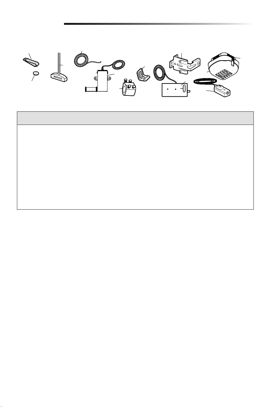
33
Repair Parts
Installation Parts
9
8
10
3
4
5
7
11
12
6
2
1
KEY PART
NO. NO. DESCRIPTION
1 29B137 Remote control visor clip
2 10A20 3V CR2032 Lithium battery
3 41A4582 Emergency release rope & handle
assembly
4 41B4494-1 2-Conductor bell wire - white and
white/red
5 041A6104 Cable tension monitor
6 041D8615 Collar with set screws
7 41C0902 Mounting bracket
8 41A5266-1 Safety reversing sensor brackets (2)
9 41A6102 Power door lock
10 41D96-1 Light lens for light
KEY PART
NO. NO. DESCRIPTION
11 41A5034 Safety Reversing Sensor kit
(receiving and sending sensors) with
2-conductor bell wire attached
12 380LM Remote Light (garage door opener
light)
NOT SHOWN
101D173 Push bar for door control
41A6288 Hardware bag for light
41A6298 Installation hardware bag
(includeshardware listed on page 5)
114-5281 Owner’s manual
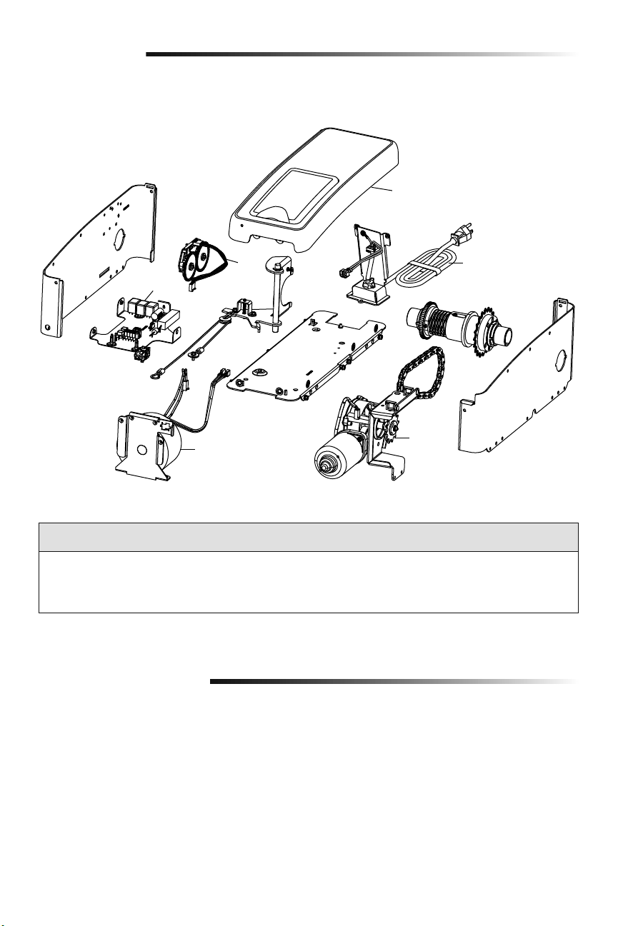
34
Repair Parts
Garage Door Opener Assembly Parts
3
2
5
4
1
6
KEY PART
NO. NO. DESCRIPTION
1 041DJ002 Logic board complete with plate
2 41A6408 Travel Module
3 41C168 Transformer
KEY PART
NO. NO. DESCRIPTION
4 41A6095 Motor with bracket
5 41B122 Power cord
6 041A6348-1 Cover
Address repair parts order to:
LiftMaster
6050 S. Country Club Rd.
Tucson, AZ 85706
For installation and service information call:
1-800-528-9131
Or visit us online at:
LiftMaster.com
Before calling, please have the model number of the garage door opener. If you are calling about a troubleshooting
issue, it is recommended that you have access to your garage door opener while calling. If you are ordering a repair
part please have the following information: part number, part name, and model number.
Contact Information
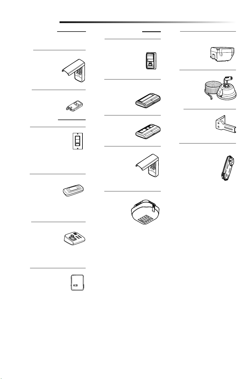
35
Extension Brackets:
(Optional) For safety
reversing sensor installation
onto the wall or floor.
Security+ 2.0
®
Wireless Door Control:
Push bar, light feature and
auxiliary button. Includes
battery.
Alternate Mounting Kit:
This kit allows model 8500
to be mounted below the
torsion bar in the case where
the torsion bar is not round
or the normal mounting area
is obstructed.
Garage Door and Gate Monitor:
Monitor open/closed status
for up to 4 myQ compatible
garage door openers or gate
operators and close them
from anywhere in the home.
Remote Light:
Enables homeowner
to turn on a work
light from their car
with their garage door
opener remote or from
anywhere in their home
with an additional LiftMaster Security+
®
remote.
Remote Light Control:
Automatically control your
lights using your garage door
opener, a Security+ 2.0
®
remote
control or a LiftMaster
®
Internet
Gateway. Plugs into any interior outlet.
Remote Light Switch:
Automatically control your
lights using your garage door
opener, a Security+ 2.0
®
remote
control or a LiftMaster
®
Internet
Gateway. Simply replaces your current
wired wall switch.
LiftMaster
®
Internet Gateway:
Internet enabled
accessory which connects
to the computer and
allows you to monitor and
control garage door openers and lighting
accessories enabled by myQ technology.
MAX Wireless Keyless Entry:
For use outside of the
home to enable access to
the garage using a 4-digit
PIN.
Accessories
890MAX
828LM
41A5281
877MAX
Mini 3-Button MAX Remote Control
829LM
Battery Backup:
Provides backup power
to the garage door
opener.
475LM
885LM
825LM
823LM
380LM
480LM
975LM
Laser Park Assist:
Laser enables
homeowners to
precisely park vehicles
in the garage.
MAX ACCESSORIES
Compatible with LiftMaster
®
garage door
openers manufactured since 1993.
MYQ ACCESSORIES
STANDARD ACCESSORIES
Single Button Remote Control:
Includes visor clip.
891LM
3-Button Remote Control:
Includes visor clip.
893LM
Wireless Keyless Entry:
For use outside of the
home to enable access to
the garage using a 4-digit
PIN.
877LM

36
Warranty
LIFTMASTER
®
LIMITED WARRANTY
LiftMaster
®
(“Seller”) warrants to the first retail purchaser of this product, for the residence in which this product
is originally installed, that it is free from defects in materials and/or workmanship for a specific period of time as
defined below (the “Warranty Period”). The warranty period commences from the date of purchase.
WARRANTY PERIOD
Parts Motor Accessories Battery Backup
5 years Lifetime 1 year 1 year
The proper operation of this product is dependent on your compliance with the instructions regarding installation,
operation, and maintenance and testing. Failure to comply strictly with those instructions will void this limited
warranty in its entirety.
If, during the limited warranty period, this product appears to contain a defect covered by this limited warranty,
call 1-800-528-9131, toll free, before dismantling this product. You will be advised of disassembly and shipping
instructions when you call. Then send the product or component, pre-paid and insured, as directed to our service
center for warranty repair. Please include a brief description of the problem and a dated proof-of-purchase receipt
with any product returned for warranty repair. Products returned to Seller for warranty repair, which upon receipt
by Seller are confirmed to be defective and covered by this limited warranty, will be repaired or replaced (at Seller’s
sole option) at no cost to you and returned pre-paid. Defective parts will be repaired or replaced with new or factory
rebuilt parts at Seller’s sole option. [You are responsible for any costs incurred in removing and/or reinstalling the
product or any component.]
ALL IMPLIED WARRANTIES FOR THE PRODUCT, INCLUDING BUT NOT LIMITED TO ANY IMPLIED WARRANTIES
OF MERCHANTABILITY AND FITNESS FOR A PARTICULAR PURPOSE, ARE LIMITED IN DURATION TO THE
APPLICABLE LIMITED WARRANTY PERIOD SET FORTH ABOVE FOR THE RELATED COMPONENT(S), AND NO
IMPLIED WARRANTIES WILL EXIST OR APPLY AFTER SUCH PERIOD. Some States and Provinces do not allow
limitations on how long an implied warranty lasts, so the above limitation may not apply to you. THIS LIMITED
WARRANTY DOES NOT COVER NON-DEFECT DAMAGE, DAMAGE CAUSED BY IMPROPER INSTALLATION,
OPERATION OR CARE (INCLUDING, BUT NOT LIMITED TO ABUSE, MISUSE, FAILURE TO PROVIDE REASONABLE
AND NECESSARY MAINTENANCE, UNAUTHORIZED REPAIRS OR ANY ALTERATIONS TO THIS PRODUCT), LABOR
CHARGES FOR REINSTALLING A REPAIRED OR REPLACED UNIT, REPLACEMENT OF CONSUMABLE ITEMS
(E.G., BATTERIES IN REMOTE CONTROL TRANSMITTERS AND LIGHT BULBS), OR UNITS INSTALLED FOR NON-
RESIDENTIAL USE. THIS LIMITED WARRANTY DOES NOT COVER ANY PROBLEMS WITH, OR RELATING TO, THE
GARAGE DOOR OR GARAGE DOOR HARDWARE, INCLUDING BUT NOT LIMITED TO THE DOOR SPRINGS, DOOR
ROLLERS, DOOR ALIGNMENT OR HINGES. THIS LIMITED WARRANTY ALSO DOES NOT COVER ANY PROBLEMS
CAUSED BY INTERFERENCE. UNDER NO CIRCUMSTANCES SHALL SELLER BE LIABLE FOR CONSEQUENTIAL,
INCIDENTAL OR SPECIAL DAMAGES ARISING IN CONNECTION WITH USE, OR INABILITY TO USE, THIS PRODUCT.
IN NO EVENT SHALL SELLER’S LIABILITY FOR BREACH OF WARRANTY, BREACH OF CONTRACT, NEGLIGENCE
OR STRICT LIABILITY EXCEED THE COST OF THE PRODUCT COVERED HEREBY. NO PERSON IS AUTHORIZED TO
ASSUME FOR US ANY OTHER LIABILITY IN CONNECTION WITH THE SALE OF THIS PRODUCT.
Some states and provinces do not allow the exclusion or limitation of consequential, incidental or special damages,
so the above limitation or exclusion may not apply to you. This limited warranty gives you specific legal rights, and
you may also have other rights, which vary from state to state and province to province.
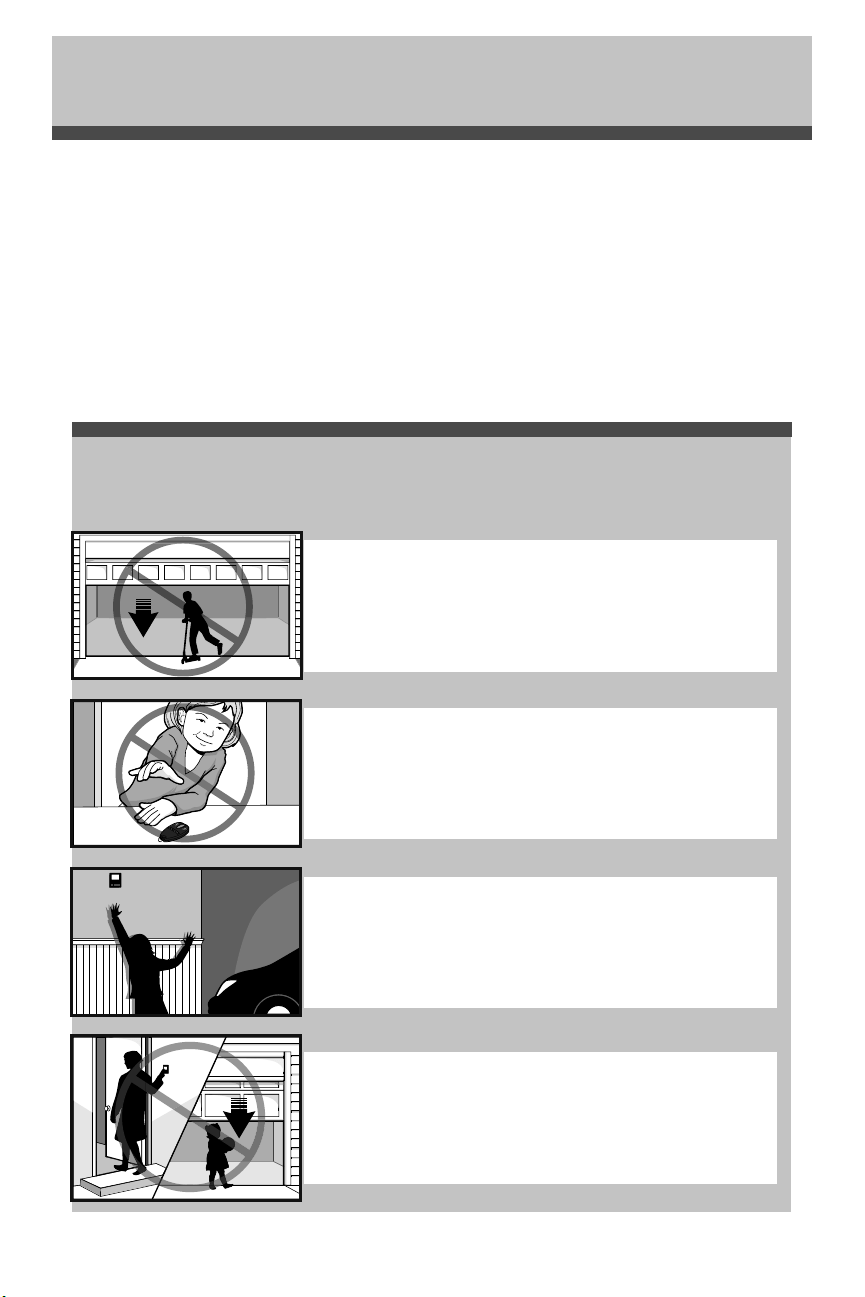
37
Automatic Garage Door Opener
Safety & Maintenance Guide
Garage Door Openers are Not Toys
Discuss garage door and opener safety with your children. Explain the danger of
being trapped under the door.
Garage Door Opener Safety – An Automatic Decision
Stay away from a moving door.
Keep transmitters and remote controls out of reach
of children. Do not let children play with or use
transmitters or other remote control devices.
The wall-mounted push button should be out of reach of children,
at least 5 feet from the nearest standing surface and away from all
moving parts. Mount and use the button where you can clearly see
the closing garage door.
Keep the door in sight until it completely closes when using the
wall-mounted push button or transmitter.
A garage door is the largest moving object in the home. An improperly adjusted garage door and opener
can exert deadly force when the door closes – which could lead to entrapment of children or adults and
subsequent injury or death.
Proper installation, operation, maintenance, and testing of the garage door and automatic opener are necessary to
provide a safe, trouble-free system.
Careless operation or allowing children to play with or use garage door opener controls are also dangerous
situations that can lead to tragic results. A few simple precautions can protect your family and friends from
potential harm.
Please review the safety and maintenance tips in this brochure carefully and keep it for reference. Check the
operation of your garage door and opener to ensure they function in a safe and trouble-free manner.
Be sure to read all Important Safety Information found in your garage door opener’s manual as it provides more
details and safety considerations than can be supplied with this brochure.
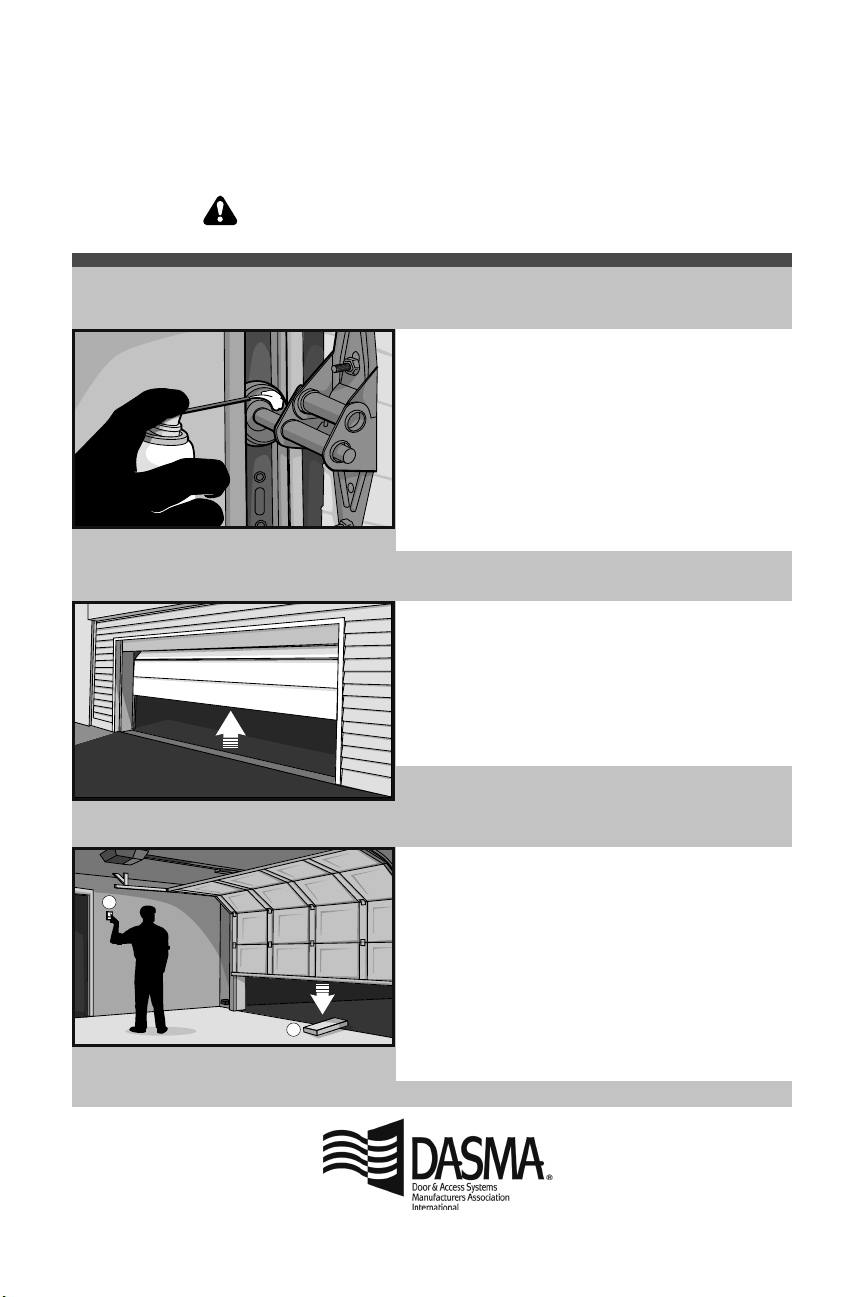
38
Routine Maintenance Can Prevent Tragedies
1
2
• Starting with the door in the closed position, use the
manual disconnect on the opener to disconnect the door.
• Look for signs of wear or damage on hinges, rollers,
springs, and door panels.
• These parts may require periodic lubrication. Check the
owner’s manual for suggested maintenance.
• If any signs of damage are evident, contact a trained door
systems technician for assistance.
• Verify the photoeye height is no higher than 6" from the
garage floor.
• Open and close the door manually using handles or
suitable gripping points.
• The door should move freely and without difficulty.
• The door should balance and stay partially open 3–4
feet above the floor.
• If you detect any signs of improper operation, contact a
trained door systems technician for assistance.
• Reconnect the opener to the door using the manual
disconnect and open the door.
• Place a 2x4 board flat in the path of the door (1) and try
to close it (2). The door should stop when it comes in
contact with the 2x4 and then reverse direction.
• Block the photoelectric sensor by waving an object in
front of the sensor and attempt to close the door. The
door should not close unless the wall-mounted push
button is manually held during operation.
• If the opener does not perform as described, contact a
trained door systems technician for assistance.
Make monthly inspection and testing of your garage door and opener system a part of your regular routine.
Review your owner’s manual for both the door and door opener. If you don’t have the owner’s manuals, contact
the manufacturer(s) and request a copy for your specific model(s). Look for the opener model number on the
back of the power unit.
Test the opener safety features:
Test the door for proper operation:
Visually check the door
and installation:
WARNING – Springs are under high tension.
Only qualified individuals should adjust them.
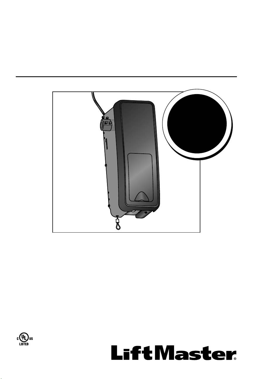
1
• ¡Favor de leer cuidadosamente este manual y los materiales de seguridad anexos!
• Guarde este manual cerca de la puerta del garaje luego de la instalación.
• La puerta NO SE CERRARÁ a menos que el Protector System
®
y el monitor de
tensión del cable estén conectados y adecuadamente alineados.
• Se deben realizar revisiones periódicas del abre-puertas de garaje para asegurar
su operación segura.
• La calcomanía con el número de modelo se ubica detrás de la puerta abisagrada
de su abre-puertas.
• NO exceda 10 ciclos completos de la operación de la puerta por hora.
• Este abre-puertas de garaje es compatible ÚNICAMENTE con accesorios myQ
®
y
Security+ 2.0
®
.
Este producto es para la instalación solamente por los técnicos especializados en
sistemas de puertas del garaje. Este producto puede requerir ajustes a los resortes
de la puerta y/o las configuraciones del riel. No use este producto en las pistas del
espacio libre o puertas del garaje que utilizan los resortes tensores.
Exclusivamente para uso residencial o uso comercial de servicio liviano
Sólo instalizar en puertas seccionales con resorte de tension
LiftMaster
300 Windsor Drive
Oak Brook, IL 60523
Abre-puertas de garaje
de montaje en la pared
Modelo 8500
V
e
a
p
a
g
i
n
a
1
8
p
a
r
a
d
e
t
a
l
l
e
s
Compatible con
reserva de
batería

2
Introducción
Estas advertencias y/o símbolos de seguridad que aparecen a lo largo de este manual le
alertarán de la existencia de riesgo de una lesión seria o de muerte si no se siguen las
instrucciones correspondientes. El peligro puede ser eléctrico (electrocución) o mecánico.
Lea las instrucciones con mucho cuidado.
Cuando vea esta palabra y/o símbolo de seguridad a lo largo de este manual le alertará
de que existe el riesgo de dañar la puerta del garaje y/o el abre-puertas de garaje si no se
siguen las instrucciones correspondientes. Lea las instrucciones con mucho cuidado.
Mecánica
Eléctricidad
Revisión de los símbolos y palabras de seguridad
Este abre-puertas de garaje ha sido diseñado para un funcionamiento seguro, siempre y cuando se instale, se pruebe, se opere y se le
dé mantenimiento como se indica a lo largo de este manual, cumpliendo al pie de la letra con todas las advertencias e instrucciones
generales aquí contenidas.
Contenido
INTRODUCCIÓN 2
Revisión de los símbolos y palabras de
seguridad .................................................. 2
Planificación ..............................................3
Preparación de la puerta del garaje ........... 4
Herramientas necesarias ...........................4
Inventario del empaque ............................. 5
Herrajes ....................................................5
ENSAMBLADO 6
Montar el aro en el abre-puertas
de garaje ...................................................6
Montar la ménsula al abre-puertas
de garaje ...................................................7
INSTALACIÓN 7
Montar el abre-puertas de garaje ..............8
Montaje de la cuerda y la manija de
desenganche de emergencia ..................... 9
Instalación del seguro de puerta
eléctrico .................................................... 9
Colocación del monitor de tensión
del cable (Requerido) ..............................10
Instalar el control de puerta
(Panel de control myQ) ...........................11
Instalación de la luz con
comando remoto .....................................12
Instalación del Protector System
®
.........13
Conectar la alimentación ......................... 16
Instalar la batería de reserva (opcional) .. 18
AJUSTES 19
Programación de los límites
del recorrido ...........................................19
Ajuste la fuerza ........................................20
Prueba del sistema de seguridad de
reversa .................................................... 21
Prueba del Protector System
®
................21
Prueba del monitor de tensión del cable . 22
Prueba del seguro de puerta eléctrico .....22
Cómo abrir la puerta manualmente ......... 22
OPERACIÓN 23
Uso del abre-puertas de garaje ............... 23
Uso del control de puerta
(Panel de control myQ) ...........................24
Cómo usar el control remoto ..................25
PROGRAMACIÓN 26
Para agregar un control remoto, llave
digital o accesorios compatibles con myQ
con el control de puerta (Panel de control
myQ) .......................................................26
LiftMaster
®
Internet Gateway
(No suministrado) ...................................27
Para eliminar todos los códigos
de la memoria del control de puerta
(Panel de control myQ) ..........................27
Cómo reprogramar la luz o luz adicional . 27
Programación adicional de llave digital
(no suministrada) ...................................28
HomeLink
®
..............................................28
MANTENIMIENTO 29
Mantenimiento del abre-puertas
de garaje .................................................29
RESOLUCIÓN DE PROBLEMAS 30
Tabla de diagnóstico ............................... 30
Resolución de problemas ........................31
Resolución de
problemas (Continuación) .......................32
PIEZAS DE REPUESTO 33
Piezas para la instalación ........................ 33
Piezas del abre-puertas de garaje ............ 34
INFORMACIÓN DE CONTACTO 34
ACCESORIOS 35
GARANTÍA 36
Guía de seguridad y mantenimiento
del abre-puertas de garaje
automático 37
ADVERTENCIA: Este producto puede exponerle a productos químicos (incluido el plomo), que a consideración del
estado de California causan cáncer, defectos congénitos u otros daños reproductivos. Para más información, visite
www.P65Warnings.ca.gov
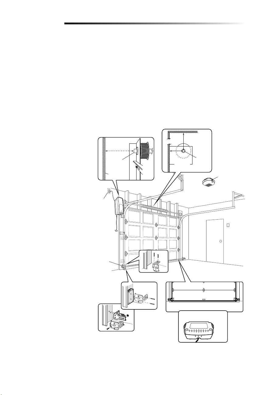
3
Planificación
Revise el área de su garaje para ver si alguna de las siguientes condiciones se aplica a
su instalación. Otros materiales podrían ser necesarios según las características de su
instalación particular.
ESTE ABRE-PUERTAS DE GARAJE ES COMPATIBLE CON:
• Puertas con barra de torsión y resortes. La barra de torsión debe ser de 2.5 cm
(1pulgada) de diámetro.
• Carretes de 10 cm a 15 cm (4 a 6 pulg.); no debe utilizarse con carretes cónicos de
más de 15 cm (6 pulg.).
• Se pueden usar tambores de 3 a 3.9 pulgadas (7.6 cm a 9.9 cm) en puertas de hasta
430 lbs (195.4 kgs).
• Puertas seccionadas de elevación alta (de hasta 137.2 cm (54 pulg.) de altura) y
estándar de hasta 4.3 m (14 pies) de altura.
• Puertas de hasta 5.5 m (18 pies) de ancho.
• Puertas de hasta 16.7 m cuadrados (180 pies).
Revise o inspeccione el área de instalación
propuesta. El abre-puertas de garaje
puede instalarse a la izquierda o a la
derecha de la puerta. Seleccione el lado
que cumpla con los requisitos que se
detallan a continuación.
a. Debe haber, como mínimo, 6.4cm
(2-1/2 de pulg.) entre la pared del
garaje y el centro de la barra de
torsión.
b. Debe haber, como mínimo, 7.6cm
(3pulg.) entre el techo y el centro de
la barra de torsión.
c. Debe haber, como mínimo, 21.6cm
(8.5pulg.) entre la pared lateral del
garaje (o obstrucción) y el extremo de
la barra de torsión.
d. La barra de torsión debe extenderse,
por lo menos, de 3.81 cm (1.5 de
pulg.) de la cojinete. Esto puede variar
dependiendo de sus requisitos de la
instalación.
e.
Se requiere una toma de corriente
eléctrica dentro de los 1.83m (6pies)
del área de instalación. Si no hay un
tomacorriente, póngase en contacto
con un electricista calificado o utilice
una alimentación eléctrica de bajo
voltaje (modelo 580LM).
f. Según la construcción del garaje, es
posible que se requieran extensiones
de soporte o bloques de madera para
instalar los sensores de reversa de
seguridad.
g. El montaje alternativo de los sensores
de reversa de seguridad en el suelo
requerirá piezas que no se incluyen.
h. Cualquier espacio entre el suelo
y la base de la puerta no debe
exceder 6mm (1/4 de pulg.).De lo
contrario, es posible que el sistema
de reversa de seguridad no funcionen
debidamente.
i. Se recomienda el uso de reserva
de batería modelo 475LM si no hay
puerta de acceso al garaje, ya que
este abre-puertas de garaje no puede
usarse junto con un mecanismo
externo de apertura de emergencia.
Introducción
NOTA: Inspeccione la barra de torsión
mientras la puerta suba y baje. Es
importante que no haya ningún movimiento
notorio hacia arriba ni abajo, ni hacia la
derecha ni la izquierda. La duración del
abre-puertas de garaje será mucho menor
si no se corrige el movimiento.
a
b
h
i
c
d
e
f
g
Barra de
torsión
6.4 cm
(2-1/2
de pulg.)
7.6 cm
(3 pulg)
Pared o
obstrucción
Barra de
torsión
21.6 cm
(8.5 pulg.)
Reserva de batería
475LM
Sensor de
seguridad
de reversa
Luz remota
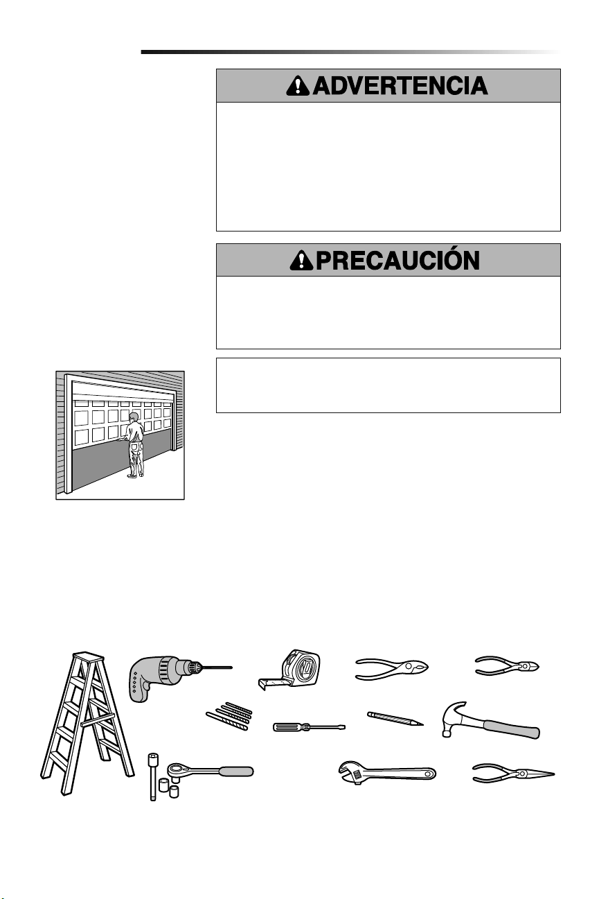
4
Pinzas
Cortador de alambre
Martillo
Desarmador
Llave de extermo
ajustable
Llaves de tuercas de 1/4 de pulg.,
5/16 de pulg., y 3/8 de pulg. y
matraca con extensión de 6 pulg.
Taladro Cinta de medir
Escalera
Lápiz
Pinzas de punta
Brocas para taladro
de 5/32 de pulg., 3/16 de pulg.,
5/16 de pulg. y 3/4 de pulg.
Introducción
Preparación de la puerta
del garaje
ANTES DE COMENZAR:
• Desarme los seguros.
• Retire cualquier cuerda que esté
conectada a la puerta del garaje.
Haga la siguiente prueba con su puerta
para verificar que esté equilibrada y que no
se atasque ni se atore:
1. Levante la puerta hasta la mitad de
su recorrido como se muestra. Suelte
la puerta. Si está equilibrada, debe
mantenerse en esa posición sólo con
el soporte de los resortes.
2. Suba y baje la puerta; observe si se
atora con algo o si se atasca.
Si su puerta se atora, se atasca o está
desequilibrada, llame a un técnico
especializado en sistemas de puertas.
Para evitar daños a la puerta y al abre-puertas:
• SIEMPRE desactive las trabas y seguros ANTES de instalar y usar el abre-puertas.
• SOLAMENTE opere el abre-puertas de garaje con corriente de 120V 60 hz con object
de evitar su mal funcionamiento y que el abre-puertas se dañe.
• NO exceda 10 ciclos completos de la operación de la puerta por hora.
Para evitar la posibilidad de LESIONES GRAVES o incluso LA MUERTE:
• Si la puerta se atora, se atasca o está desbalanceada, SIEMPRE llame a un técnico
profesional para que la repare. Es posible que una puerta de garaje que no esté bien
balanceada NO retroceda cuando se requiera.
• NUNCA trate de aflojar, mover, ni ajustar la puerta del garaje, los resortes, los
cables, las poleas, las ménsulas ni los pernos, pues TODAS estas piezas están bajo
una tensión EXTREMA.
• Para evitar interferencias, desactive TODAS las trabas y quite TODAS las cuerdas
conectadas a la puerta del garaje, ANTES de instalar y poner en uso el abre-puertas
de garaje.
Herramientas necesarias
Durante el montaje, instalación y ajuste del abre-puertas de garaje, las instrucciones
indicarán usar las herramientas que aparecen en la siguiente illustración.
Especificaciones
Voltio .....................................120 Vca - 60 Hz, SOLAMENTE
Corriente. . . . . . . . . . . . . . . . . . . . . . . . . . . . . . . . . . . . . . . . . . . . . . . . . . . . 1.0 AMP
Puerta seccionada
Contador del esfuerzo de
torsión (no mostrado)
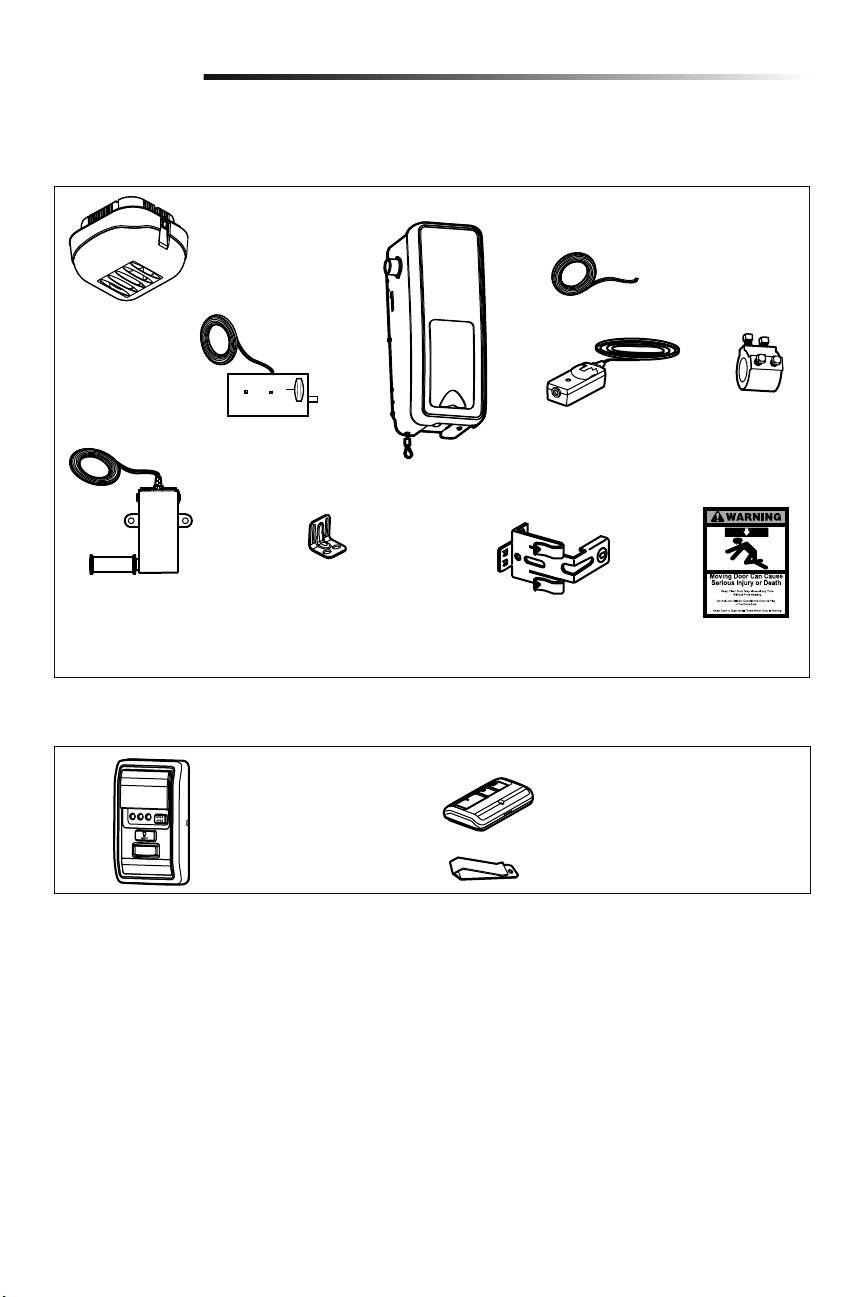
5
Inventario del empaque
Introducción
Luz remota
(Luz del abre-puertas
de garaje) con bolsa
de piezas
Seguro de puerta eléctrico
con un par de conductores
(blanco/blanco-negro) con
conector
Cable del timbre de
2 conductores, Blanco
y Blanco/Rojo
Abre-puertas
de garaje
Monitor de tensión del
cable con cables de
timbre de 2 conductores,
Verde/Blanco
Mensula
Collar con
tornillos
de fijación
Ménsulas para sensor
de seguridad (2)
Protector System
®
(2)
Sensores de seguridad de
reversa (1 emisor y 1
receptor) con cable de timbre
de 2 conductores, (Blanco y
Blanco/Negro) conectado
Etiquetas de
seguridad y
literatura
Herrajes
Los accesorios suministrados con el abre-puertas de garaje dependerá del modelo comprado. Si falta alguna pieza, revise con cuidado el
material de empaque.
NO MOSTRADO: Plantilla del seguro
Tornillo núm. 10-32 (2)
Tornillo 14-10x2 pulg. (4)
Manija
Cuerda
Tornillo 1/4 de pulg.-20x1/2 de pulg. (2)
Tarugos para panel de pared
(atornillable) (2)
Accesorios incluidos
Broche de visera para control remoto
Control remoto de 3 botones
Modelo 893MAX (1)
Control de puerta
(myQ Panel de control)
Modelo 889LM
Tornillo 8-32x1 pulg. (2)
Tornillo 6ABx1-1/4 de pulg. (2)
Tarugos para panel de pared (2)
Tornillo 6-32x1 pulg. (2)
Perno de coche de 1/4 de pulg.-20x1/2
de pulg. (2)
Tuerca mariposa de 1/4 de pulg.-20 (2)
INVENTARIO DE ILUMINACIÓN REMOTA:
Tarugos para panel de pared
(atornillable) (2)
Tornillo núm. 6x1 pulg. (2)
Tornillo núm. 4-20x7/16 de pulg. (2)
Gancho de pestillo (1)
Gancho de bisagra (1)
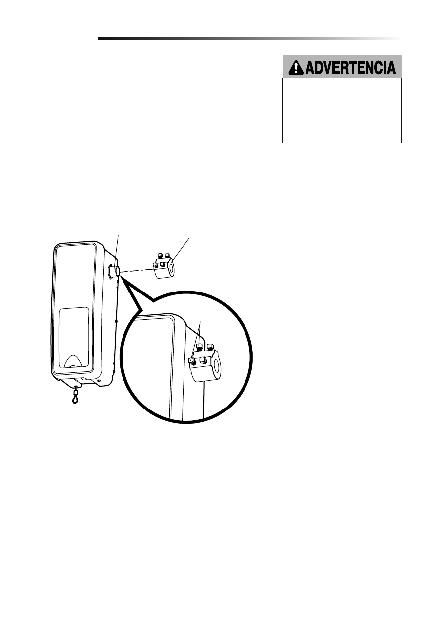
6
Para evitar problemas con la instalación, no opere el abre-puertas de garaje hasta
que llegue al paso de la instalación correspondiente.
El abre-puertas de garaje puede montarse a izquierda o a derecha de la puerta (véase la
sección Planificación de la página 3). Las ilustraciones muestran la instalación del
lado izquierdo.
1.
Afloje los tornillos de fijación.
2.
Montar el aro en el eje del motor del abre-puertas de garaje. El lado el aro de mayor
diámetro va del lado del eje del motor. Asegúrese de que el collar esté colocado
íntegramente en el eje del motor hasta llegar al fondo.
3. Los tornillos del aro deben quedar hacia afuera y en una posición fácil alcanzar.
4. Ajuste firmemente los 2 tornillos de fijación de cabeza cuadrada más cercanos al eje
del motor haciendo un giro de 1/4 a 1/2 después de hacer contacto con el eje del
motor.
Montar el aro en el abre-puertas de garaje
Ensamblado
1
Para evitar la posibilidad de una LESIÓN
GRAVE o INCLUSO LA MUERTE,
el collar DEBE estar correctamente
apretado. Es posible que la puerta
no retroceda correctamente o que
se pierdan los límites debido al
deslizamiento del collar.
Tornillos de
fijación
Collar
Eje del
motor
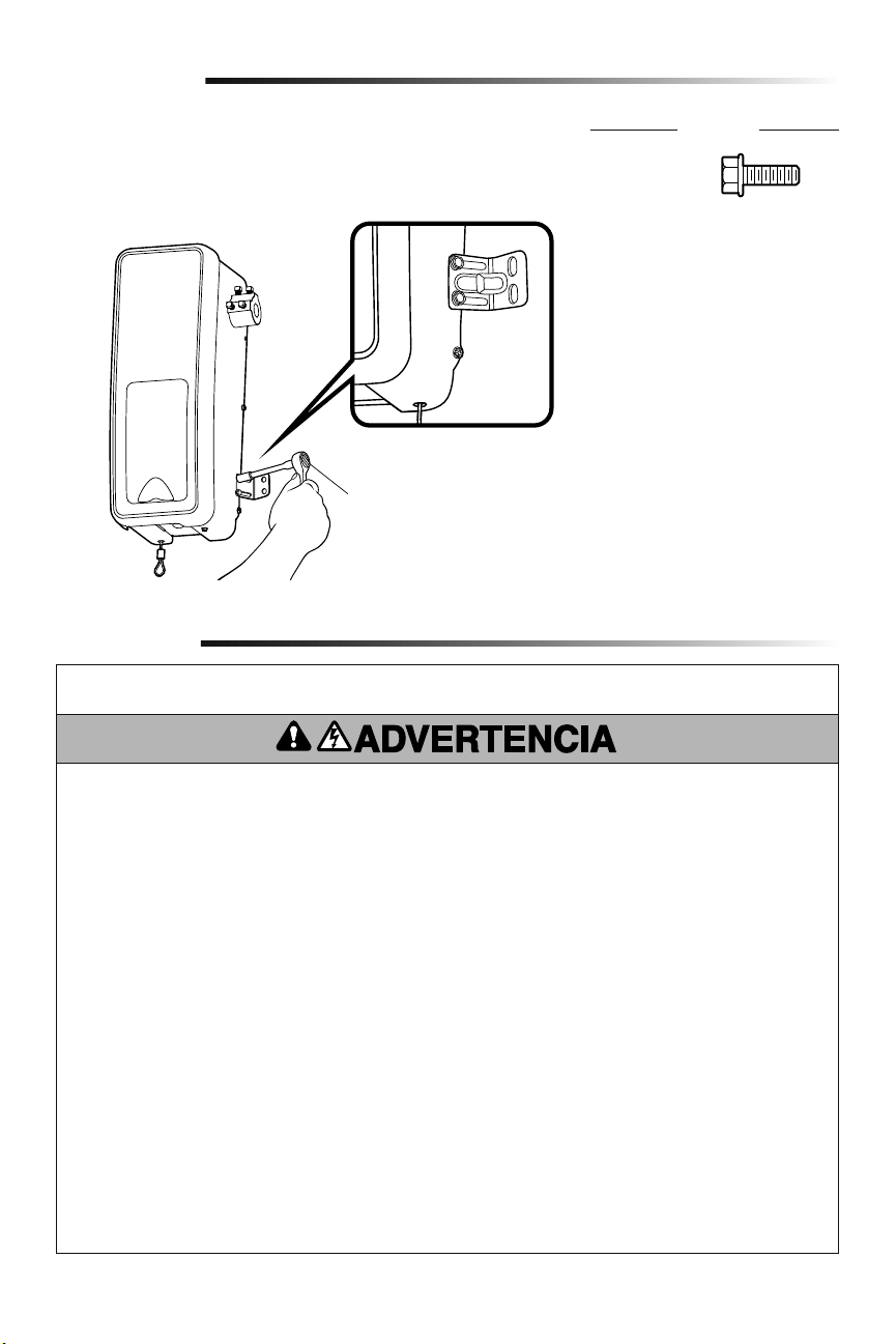
7
INSTRUCCIONES DE INSTALACIÓN IMPORTANTES
Instalación
Para reducir el riesgo de
LESIONES GRAVES o DE MUERTE:
1. LEA Y SIGA TODAS LAS INSTRUCCIONES DE INSTALACIÓN
Y LAS ADVERTENCIAS RELACIONADAS.
2. Instale el abre-puertas de garaje SOLAMENTE en puertas
de garaje que estén bien equilibradas y lubricadas. Si la
puerta no está debidamente equilibrada es posible que NO
retroceda cuando así se requiera y podría ocasionar una
LESIÓN ACCIDENTAL GRAVE o INCLUSO LA MUERTE.
3. TODAS las reparaciones de los cables, resortes y otras
partes las DEBE llevar a cabo un técnico especializado en
sistemas de puertas, ANTES de instalar el abre-puertas de
garaje.
4. Desarme TODOS los seguros y retire TODAS las cuerdas
conectadas a la puerta del garaje ANTES de instalar el
abre-puertas de garaje, para evitar que estas se enreden.
5. Si es posible, instale el operador a una distancia de 2.13 m
(7 pies) o más por encima del piso.
6. Monte la manija de desenganche de emergencia de modo
que esté al alcance, pero con una altura mínima de 1.83 m
(6 pies) del piso para evitar el contacto con los vehículos y
que se suelte accidentalmente.
7. No conecte NUNCA el abridor de la puertas de garaje a una
fuente de energía eléctrica hasta que se le indique.
8. NUNCA lleve puestos relojes, anillos o prendas sueltas
durante la instalación o funcionamiento del abre-puertas de
garaje, pues podrían atorarse en la puerta del garaje o en los
mecanismos del abre-puertas.
9. Instale el control del abre-puertas de garaje para paredes:
• Adonde se pueda ver la puerta del garaje.
• fuera del alcance de los niños pequeños a una altura
mínima de 1.5 m (5 pies) por encima de pisos, descansos,
peldaños o cualquier otra superficie de tránsito peatonal
adyacente.
• Alejado de TODAS las partes móviles de la puerta.
10. Instale el cartel de liberación de emergencia. Sujete el cartel
sobre o junto a la liberación de emergencia. Instale la placa
de advertencia de aprisionamiento junto al control de la
puerta, en un lugar visible.
11. Coloque la etiqueta de prueba de reversa de seguridad/
liberación de emergencia a plena vista en la parte interior de
la puerta.
12. Al terminar la instalación, pruebe el funcionamiento de
reversa de seguridad. La puerta DEBE retroceder al entrar en
contacto con un objeto de 3.8 cm (1-1/2 de pulg.) de altura
(o un tablón de madera de 2 X 4) acostado en el piso.
Montar la ménsula al abre-puertas de garaje
2
1. Con los tornillos autorroscantes suministrados, colocar el lado de la ménsula con la
muesca del mismo lado en que se montó el aro en el abre-puertas de garaje.
NOTA: No ajustar los tornillos hasta que así se indique en las instrucciones.
Matraca y dado
Ensamblado
HERRAJES
Tornillo núm.
10-32 (2)
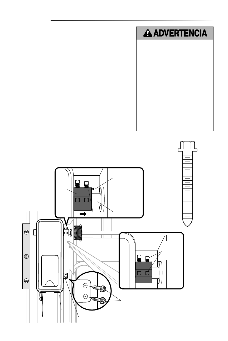
8
Placa de
soporte
Collar
Bara de torsión
.Espacio mínimo
de 6 mm
(0.25 pulg.) entre
la placa de apoyo
y el collar
Ménsula de montaje
Tornillos 14-10 x 2 pulg.
Tornillos de
fijación
(Barra de
torsión)
Instalación
PIEZAS
Montar el abre-puertas de garaje
1
Para evitar la posibilidad de una LESIÓN GRAVE
o INCLUSO LA MUERTE:
• Se DEBEN usar anclas para concreto si se
monta el soporte en la mampostería.
• NUNCA trate de aflojar, mover ni ajustar la
puerta del garaje, los resortes, los cables,
las poleas, los soportes ni sus piezas, pues
TODAS estas piezas están bajo una tensión
EXTREMA.
• SIEMPRE llame a un técnico especializado
en sistemas de puertas si la puerta del garaje
se atora, se atasca o está desequilibrada. Es
posible que una puerta de garaje que no esté
equilibrada NO retroceda cuando se requiera.
• El operador DEBE estar montado a un ángulo
correcto de la barra de torsión para evitar el
desgaste prematuro del collar.
• El abre-puertas de garaje DEBE estar
montado a un ángulo adecuado para evitar el
desgaste prematuro del collar.
Tornillo
14-10x2 pulg. (2)
HERRAJES
NOTA: Para opciones de montaje adiciónales, vea la página de accesorios.
1. Cierre completamente la puerta del garaje.
2.
Deslizar el abre-puertas de garaje hacia el extremo de la barra de torsión.
Si la barra fuera muy larga o estuviera dañada, podría ser necesario
cortarla.
Verificar que el aro NO haga contacto con la placa de soporte.
3. Alinear el abre-puertas de garaje y nivelarlo verticalmente. Verificar que
la ménsula de montaje esté apoyada sobre una súperficie sólida tal como
madera, concreto o un soporte de puerta. Si está realizando la instalación
sobre tablaroca, la ménsula de montaje DEBE sujetarse a un montante.
4. Una vez que el abre-puertas de garaje quede alineado, marcar los agujeros
de fijación de la ménsula de montaje, Si fuera necesario ajustar los
tornillos del aro en la barra de torsión para mantener fijo el abre-puertas
de garaje mientras hacen los agujeros.
NOTA: El abre-puertas de garaje no debe quedar a ras de la pared.
5. Desmontar el abre-puertas de garaje de la barra de torsión. Taladre
orificios de 3/16 de pulg. en los lugares marcados. Hacer los agujeros que
sean necesarios en la placa de acero.
6. Volver a colocar el abre-puertas de garaje en la barra de torsión hasta que
los agujeros pilotos queden alineados con la ménsula.
7. Ajuste los 2 tornillos de fijación de cabeza cuadrada en la barra de
torsión. Si la barra de torsión es hueca, ajuste los tornillos de 3/4 a 1 giro
completo después de hacer contacto con la barra. Si la barra de torsión es
sólida, ajuste los tornillos de 1/4 a no más de 1/2 giro después de hacer
contacto con la barra. Si está instalando una barra de torsión ranurada,
NO ajuste los tornillos en las ranuras.
8. Fijar la ménsula de montaje a la pared y al abre-puertas de garaje. Para
fijar la ménsula a la pared usar tornillos de 14-10x2 pulg.
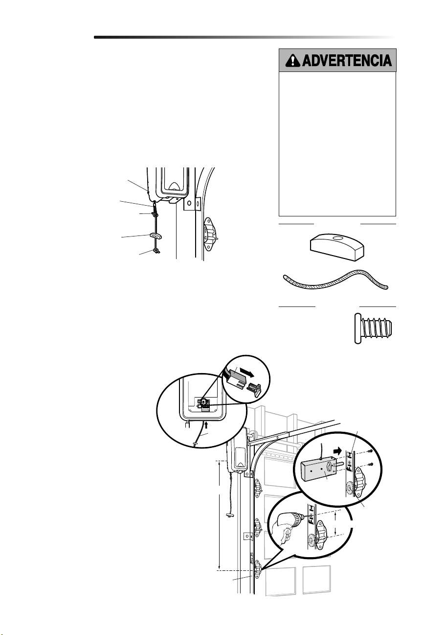
9
Montaje de la cuerda y la manija de desenganche
de emergencia
Instalación del seguro de puerta eléctrico
2
3
1. Pase un extremo de la cuerda a través del agujero en la parte superior de la manija
roja de manera que "AVISO" lee al derecho. Asegúrela con un nudo sencillo a, por lo
menos, 2.5 cm (1 pulg.) del extremo de la cuerda, para evitar que se suelte.
2. Inserte el otro extremo de la cuerda en el lazo del cable de desenganche de
emergencia. Ajuste la longitud de la cuerda para que la manija no se encuentre a
una distancia superior a los 1.83 m (6 pies) del suelo. Haga un nudo igual en ese
extremo.
NOTA: Si es necesario cortar la cuerda, queme el extremo cortado con un fósforo o
encendedor para evitar que el cordón se deshilache.
1. El seguro de puerta eléctrico debe
montarse a no más de 3.05 m (10
pies) del abre-puertas de garaje, con
una distancia de aproximadamente
7.6 cm (3 pulgadas) entre el centro de
un rodillo de la puerta y el agujero del
cerrojo del seguro. Si fuera posible,
montarla del mismo lado que el abre-
puertas de garaje. El segundo rodillo
desde la parte de abajo es el lugar
para la mayoría de las instalaciones.
2.
Verificar que el riel guía esté limpio
y montar la plantilla del seguro en el
mismo.
3. Taladre los orificios siguiendo las
marcas de la plantilla.
4. Ajustar el seguro de puerta eléctrico
sobre la parte externa del riel guía
del abre-puerta con los tornillos
suministrados.
5. Instalar el conductor por la pared,
hasta el abre-puertas de garaje. Use
grapas con aislamiento para sujetar
el cable en varios lugares. Pasar el
conductor por la parte inferior del
abre-puerta de garaje.
6. Enchufar el conector al abre-puertas
de garaje.
Instalación
El seguro de puerta eléctrico se utiliza para evitar que la puerta del garaje se abra
manualmente una vez que esté completamente cerrada.
Abre-puertas de
garaje
Cable de desenganche
de emergencia
Nudo sobre el extremo
de la cuerda
Nudo sobre el extremo
de la cuerda
Manija de desenganche
de emergencia
Para evitar la posibilidad de una
LESIÓN GRAVE o INCLUSO LA
MUERTE si la puerta del garaje se cae:
• Si es posible, utilice la manija de
desenganche de emergencia para
desenganchar la puerta SÓLO
cuando la puerta del garaje esté
CERRADA. Si los resortes están
débiles o rotos, o bien si la puerta
está desequilibrada y se abre,
ésta podría caerse rápida y/o
inesperadamente.
• NUNCA use la manija de
desenganche de emergencia a
menos que la entrada al garaje esté
libre de obstrucciones y no haya
ninguna persona presente.
Rodillo
Aprox. 7.6 cm (3 pulg.)
3.05 m (10 pies) max.
Riel guia del garaje
Plantilla del
seguro
HERRAJES
Tornillo 1/4 de pulg.-
20x1/2 de pulg. (2)
Cuerda
Manija
HERRAJES
Conector
Seguro de
puerta
eléctrico
Cable de
timbre

10
HERRAJES
Colocación del monitor de tensión del cable (Requerido)
4
NOTA: El monitor de tensión del cable se envía de fábrica para realizar la instalación del
lado izquierdo. Es recomendable que el monitor de tensión de cable se instale del mismo
lado de la puerta que el abre-puertas de garaje. Para instalar del lado derecho quitar el
retén del rodillo y montarlo del lado opuesto del monitor de tensión del cable.
1. Asegúrese de que el cable de la puerta es de aproximadamente 19 mm (3/4 de pulg.)
de la superficie de montaje. Ajustes de puerta pueden ser necesarios para alcanzar la
profundidad adecuada para el cable de la puerta.
2.
Colocar el monitor de tensión del cable tan cerca del cilindro como sea posible. El
monitor de tensión del cable debe montarse sobre un soporte estructural de madera
y el rodillo debe estar libre de obstrucciones.
NOTA: No debe haber obstrucciones en el lugar de instalación que impide que el
monitor de tensión de cable se cierre por completo cuando detecta aflojamiento.
3. Marque y taladre orificios de 5 mm (3/16 de pulg.) para los tornillos (no se requieren
orificios para las anclas).
NOTA: Si no es posible montar el monitor de tensión del cable en madera con los
tornillos de cabeza cuadrada provistos, se puede montar en paneles de yeso de 1
cm (1/2 de pulg.) o más gruesos usando las anclas para panel de pared (2) y los
tornillos núm. 8 (2) proporcionados en la bolsa de piezas.
4. Sujete el monitor de tensión del cable a la pared con las piezas provistas. Asegúrese
de que el rodillo esté sobre el cable.
5.
Instalar el cable hasta el abre-puertas de garaje. Usar broches con aislamiento para
fijar el cable.
6. Conectar el cable a los terminales verdes del abre-puerta de garaje (la polaridad no
tiene importancia).
NOTA: El cable debe estar tenso en todo su recorrido. Asegúrese de que no haya
aflojamiento en el cable del lado opuesto de la puerta de garaje durante la operación
normal. Reajustar el tendido del cable si quedara flojo durante el desplazamiento de
la puerta.
Tambo
Para introducir o
soltar el cable,
empuje la lengüeta
hacia dentro con la
punta de un
destornillador.
(al monitor de tensión de cable)
(al abre-puertas de garaje)
BLANCO/
VERDE
Pared
5-15 cm
(2 pulg.-
6 pulg.)
Monitor de tensión
del cable
Rodillo del monitor
de tensión del cable
3-6 mm
(1/8 de
pulg. -1/4
de pulg.)
Instalación
El monitor de tensión del cable DEBE
estar conectado y correctamente
instalado antes de que el abre-puertas
de garaje se mueva hacia abajo.
El monitor de tensión del cable detecta
aflojamiento del cable a CUALQUIER
momento e invierte la dirección de
movimiento de la puerta, eliminando
llamadas innecesarias de servicio.
VISTA DE LADO
Tornillo
8-32x1
pulg. (2)
Tarugos para panel de
pared (atornillable) (2)
Tambo
Rodillo del
monitor de
tensión del cable
Cable
Approx. 19 mm
(3/4 de pulg.)
Tornillo
14-10x2 pulg. (2)
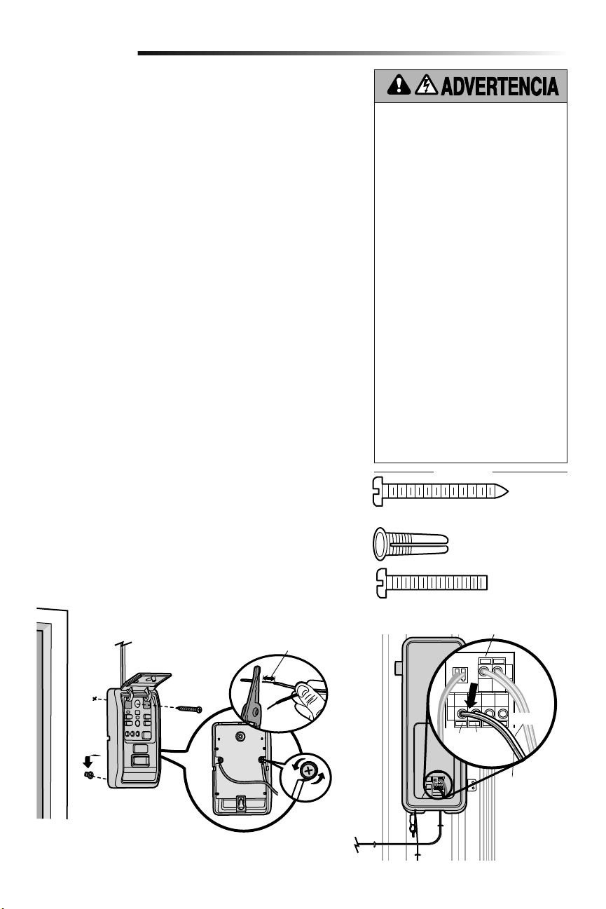
11
Instale el control de la puerta de manera que quede a la vista desde la puerta,
donde los niños pequeños no lo puedan alcanzar, a una altura mínima de 1.5 m
(5 pies) por encima de pisos, descansos, peldaños o cualquier otra superficie de
tránsito peatonal adyacente y lejos de TODAS las partes movibles de la puerta.
Si se usa una caja para instalar el control, no es necesario hacer agujeros ni colocar
tarugos en la pared. Simplemente usar los agujeros de la misma caja.
NOTA: Por el consumo de energía, este control de puerta (Modelo 889LM) no
puede usarse con ningún otro control cableado conectado al abre-puertas de garaje.
Si fuera necesario otro control de puerta, el modelo inalámbrico 885LM puede
programarse con el control de puerta (Modelo 889LM).
1. Elimine 11 mm (7/16 de pulg.) de aislamiento de un extremo del conductor y
separe los alambres.
2.
Conectar los cables al control de puerta. Asegúrese de que la polaridad sea
lacorrecta.
• Cable rojo al terminal RED (rojo).
• Cable blanco al terminal WHT (blanco).
3. Marque la ubicación del agujero de montaje inferior y abra un agujero de
4mm (5/32 de pulg.).
4. Instale el tornillo inferior, dejando que sobresalga 3 mm (1/8 de pulg.) de
lapared.
5. Posicione el agujero inferior del control de la puerta sobre el tornillo y
deslícelo hacia abajo hasta que esté en su lugar.
6. Levante la barra de empuje y marque el agujero superior.
7. Retire el control de la puerta de la pared y abra un agujero de 4 mm
(5/32depulg.) para el tornillo superior.
8. Posicione el agujero inferior del control de la puerta sobre el tornillo y
deslícelo hacia abajo hasta que esté en su lugar. Coloque el tornillo superior.
9. Tienda los cables blanco y rojo/blanco entre el control de la puerta y el
abre-puertas de garaje. Fijar el cable a la pared y al techo con los broches (no
aplicable a instalaciones con cajas de conexión ni precableadas). No perfore
el cable con las grapas ya que podría causar un cortocircuito o la apertura
delcircuito.
10. Pele 11 mm (7/16 de pulg.) de aislamiento en el extremo del cable cercano al
abre-puertas de garaje. Conecte el cable a los terminales del abre-puertas de
garaje: blanco a blanco y rojo/blanco a rojo.
11. Sujete la calcomanía de advertencia en la pared cerca del control de la puerta.
NOTA: NO conecte la energía eléctrica ni haga funcionar el abre-puertas de garaje
en este momento. La puerta se moverá hasta la posición totalmente abierta
pero no volverá a la posición cerrada hasta que se hayan conectado y alineado
correctamente los sensores de reversa de seguridad. Consulte en la página 13.
Instalar el control de puerta (Panel de control myQ)
5
Instalación
Para evitar la posibilidad de una LESIÓN GRAVE
o INCLUSO LA MUERTE por electrocución:
• ANTES de instalar el control de la puerta,
asegúrese de que la energía eléctrica NO esté
conectada.
• Conecte SÓLO a cables de bajo voltaje de
7-28VOLTIOS.
Para evitar la posibilidad de una LESIÓN GRAVE
o INCLUSO LA MUERTE cuando la puerta del
garaje se esté cerrando:
• Instale el control de la puerta de manera que
quede a la vista desde la puerta, donde los
niños pequeños no lo puedan alcanzar, a una
altura mínima de 1.5 m (5 pies) por encima
de pisos, descansos, peldaños o cualquier
otra superficie de tránsito peatonal adyacente
y lejos de TODAS las partes movibles de la
puerta.
• NUNCA permita que los niños hagan funcionar
o jueguen con los botones del control de la
puerta ni con los transmisores del control
remoto.
• Abra/cierre una puerta de garaje SÓLO si la
puede ver claramente, si está correctamente
instalada y si no hay ninguna obstrucción en
su recorrido.
• SIEMPRE mantenga la puerta de garaje a la
vista hasta que esté completamente cerrada.
NUNCA permita que alguien cruce por debajo
de una puerta de garaje que se está cerrando.
HERRAJES
Rojo Blanco
BLANCO/
ROJO
BLANCO
Para introducir o soltar el cable, empuje la lengüeta
hacia dentro con la punta de un destornillador.
11 mm (7/16 de pulg.)
Tornillo 6ABx1-1/4 de pulg. (instalación estándar) (2)
Tornillo 6-32x1 pulg.
(pre-cableado) (2)
Tarugos para panel de
pared (2)
(al abre-puertas de garaje)
(al control de puerta)
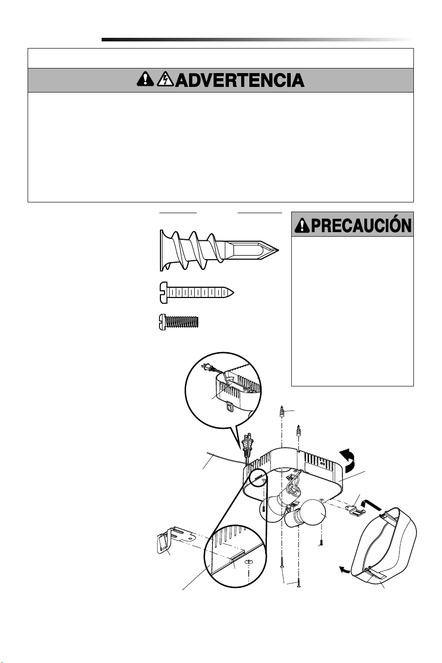
12
La luz con comando remoto del abre-puertas
de garaje puede enchufarse directamente
a un tomacorriente de 120 V. Seleccione la
ubicación apropiada en el techo para montar
la luz dentro de 1.83 m (6 pies) de una
salida eléctrica para que el cordón y la luz
estén lejos de piezas móbiles.
1. Instale los ganchos para la bisagra
y para el pestillo. Los ganchos se
deslizan entre la placa de metal y el
alojamiento de plástico de cada lado
de la base de la luz.
2. Colocar los tornillos en el techo
dejando expuesto 3 mm (1/8 de pulg.)
de filetes de rosca.
NOTA: Si instala la luz remota en un
panel de pared y no puede encontrar
una viga del techo, utilice los tarugos
para panel de pared incluidos. No se
requieren orificios para los tarugos de
panel de pared.
3. Determine la longitud del cable de
corriente requerida para alcanzar
la toma de corriente más cercana.
Enrolle el cable sobrante alrededor del
sujetador de cable situado en el lado
superior de la base de la luz.
4.
Instale la base de la luz apretando
los tornillos y girando la base en la
dirección de las manecillas del reloj
para fijar la luz en su lugar.
5. Instale dos bulbs de typo A19
incandescente o flourescente
compacto. Máximo de 100 vatios cada
bulb, 200 vatios total.
NOTA: No use lámparas de LED ya que
pueden reducir el alcance o incluso el
funcionamiento del control remoto.
6. Instale el cristal de la luz enganchando
un extremo del cristal en la bisagra y
empujando hacia arriba el otro extremo
para que se sujete en su lugar.
7. Enchufe la luz a la toma de corriente.
NOTA: La luz no funcionará hasta que
se active el abre-puertas de garaje.
Varios operadores en el mismo garaje
pueden ocasionar interferencia entre
las luces. Programe todas las luces a
un operador para evitar interferencia.
Instalación de la luz
con comando remoto
6
Instalación
Para evitar un posible
SOBRECALENTAMIENTO del
portabombillas:
• NO utilice bombillas de cuello corto
ni de tipo especial.
• NO utilice bombillas halógenas.
Utilice SÓLO bombillas
incandescentes.
• NO utilice bombillas más grande
que 100W.
• SÓLO utilice bombillas de tamaño
A19.
Para proporcionar una alerta visual
adecuada, las bombillas del abre-
puertas de garaje DEBEN ser de un
mínimo de 40 vatios (o equivalentes).
INSTRUCCIONES DE SEGURIDAD IMPORTANTES
Para reducir el riesgo de
LESIONS GRAVES o DE MUERTE:
1. Esta luminaria portátil tiene un enchufe con clavijas de
polaridad diferenciada (una clavija es más ancha que la otra)
como característica para reducir el riesgo de choque eléctrico.
2. Este enchufe encaja en una toma de corriente para clavijas de
polaridad diferenciada de una SOLA manera.
3. Si el enchufe no entra correctamente en la toma de corriente,
invierta la posición de el enchufe.
4. Si aún así no entra, diríjase a un electricista profesional.
5. NUNCA use una extensión a menos que el enchufe se pueda
enchufar por completo.
6. NO modifique el enchufe.
7. La luz es SOLAMENTE para montaje en el techo y
aplicaciones interiores.
Gancho de
pestillo
Tornillo
de la base
de la luz
Tornillos
Cristal de la luz
Tarugos para panel de pared
Sujetador
de cable
Máximo
100W
Placa de
metal
Alojamiento
de plástico
Gancho de bisagra
Tarugos para panel de pared (atornillable) (2)
HERRAJES
Tornillo de la base de la luz
núm. 4-20x7/16 de pulg. (2)
Tornillo núm. 6x1 pulg. (2)
Base de luz
Antena debe estar
completamente
expuesto para prevenir
comportamiento de la
luz intermitente.
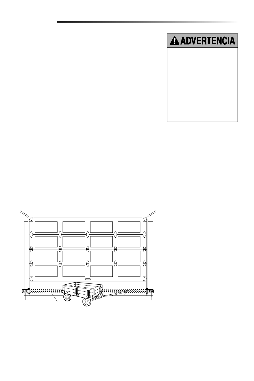
13
El sensor de seguridad de reversa se debe conectar y alinear antes de que se haga
la puerta por primera vez. Este es un sistema de seguridad requerido y no puede ser
incapacitado.
INFORMACIÓN IMPORTANTE SOBRE EL SENSOR DE SEGURIDAD DE
REVERSA
Bajo condiciones normales de instalación, conexión y alineación, el sensor detectará
cualquier obstáculo que interrumpa o interfiera con el haz electrónico. El emisor, que tiene
una luz indicadora ámbar, transmite un haz invisible de luz hacia el receptor, que tiene una
luz indicadora verde. Si hubiera una obstrucción en la trayectoria del haz de luz mientras
la puerta está bajando, se invertirá la dirección del movimiento y la puerta volverá a su
posición de abierta. La luz del abre-puertas destellará 10veces para indicar el evento.
Ambas piezas del sistema se deben instalar del lado interno del garaje, con el emisor y
el receptor enfrentados y alineados, a una altura no mayor de 15 cm (6 pulg.) sobre el
piso. Es indistinto el lado en que se instalen (izquierdo o derecho) el emisor y el receptor,
siempre y cuando el receptor nunca reciba luz solar en forma directa.
Las ménsulas de montaje están diseñadas para engancharse directamente a la guía de
puertas seccionales de garajes, sin necesidad de usar otros accesorios de fijación.
Si fuera necesario montar el dispositivo en la pared, las ménsulas de montaje se deben
fijar firmemente a una superficie sólida, tal como el encofrado o vigas de la pared. Si
fuera necesario, se pueden comprar ménsulas de prolongación (véanse los Accesorios
disponibles). Se la instalación se realiza en mampostería, es conveniente montar las
unidades sobre un trozo de madera, ya que esto facilita hacer nuevos agujeros si fuera
necesario reubicar las unidades.
Asegúrese de que no hayan obstrucciones ni interferencias con la trayectoria del haz.
Durante el cierre de la puerta, ninguna de sus partes ni ninguno de sus accesorios y
componentes debe interrumpir el haz.
ANTES de instalar el sensor de reversa
de seguridad, asegúrese de que NO
esté conectada la alimentación eléctrica
al sistema.
Para evitar la posibilidad de un
accidente GRAVE o FATAL durante el
cierre de la puerta del garaje:
• Preste atención a la conexión y
alineación del sensor de seguridad
de reversa. Este sistema de
seguridad NO DEBE quedar anulado.
• Instale el sensor de seguridad de
reversa a una altura del piso que NO
SEA SUPERIOR a 15 cm (6 pulg.).
Instalación
Sensor de
seguridad de
reversa 15 cm
(6 pulg.) sobre
el piso, máximo
Sensor de
seguridad de
reversa 15 cm
(6 pulg.) sobre
el piso, máximo
Haz invisible
de luz área
protegida
Instalación del Protector System
®
7
Vista de la puerta desde dentro del garaje
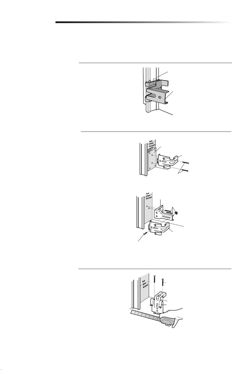
14
OPCIÓN C: Instalación en el piso
1. Utilice bloques de madera o extensiones de soporte (consulte
Accesorios) para elevar los soportes de los sensores, de
modo que los cristales se encuentren a una distancia no
superior a las 15 cm (6 pulg.) del piso.
2. Mida cuidadosamente los ensambles derecho e izquierdo y
colóquelos a la misma distancia de la pared. Asegúrese de
que las piezas de la puerta no obstruyan el rayo.
3. Sujete los soportes al suelo con anclas para concreto, como
se muestra.
Instalación
Fije el pedazo de madera a la pared, con
tirafondos (no incluidos)
Fijar con tarugos para concreto
(no incluidos)
OPCIÓN A: Instalación de la guía
1. Deslice los brazos curvados por encima del borde
redondeado de cada guía de la puerta. Los brazos curvados
deben mirar hacia la puerta. Coloque el soporte a presión
contra el costado de la guía. Debe montarse a ras, con
el resalto sobre el borde trasero de la guía, tal como se
muestra.
Si la guía de su puerta no sostiene firmemente el soporte, se
recomienda la instalación en la pared.
OPCIÓN B: Instalación en la pared
1. Coloque el soporte contra la pared, de modo que los brazos
curvados miren hacia la puerta. Asegúrese de que haya
suficiente espacio libre para que el rayo del sensor no quede
obstruido.
2. Si se requiere mayor profundidad, pueden utilizarse bloques
de madera o una extensión de soporte (consulte Accesorios).
3. Utilice los orificios de montaje del soporte como plantilla para
ubicar y taladrar 2 orificios de 5 mm (3/16 de pulg.) en la
pared, a cada lado de la puerta y a una distancia que no sea
superior a las 15 cm (6 pulg.) del suelo.
4. Sujete los soportes a la pared con tornillos de cabeza
cuadrada (no incluidos).
Si utiliza extensiones de soporte o bloques de madera, ajuste
los ensambles derecho e izquierdo a la misma distancia de la
superficie de montaje. Asegúrese de que las piezas de la puerta no
obstruyan el rayo.
INSTALACIÓN DE LOS SOPORTES
Asegúrese de que el abre-puertas no esté conectado a la energía eléctrica. Instale y alinee los soportes, de modo que los sensores de
reversa de seguridad se enfrenten de un extremo al otro de la puerta. El rayo no debe encontrarse a una distancia superior a las 15 cm
(6pulg.) del suelo. Los soportes pueden instalarse de uno de los tres modos a continuación.
Guía de puerta
Ménsulas para sensor de
seguridad de reversa
Ménsulas para sensor de
seguridad de reversa
Tirafondos (no incluida)
(Suministrado con ménsula de extensión)
Ménsula de extensión (véase la
sección Accesorios)
Ménsulas para sensor de
seguridad de reversa
(Suministrado con
ménsula de extensión)
Ménsulas para sensor de seguridad
de reversa
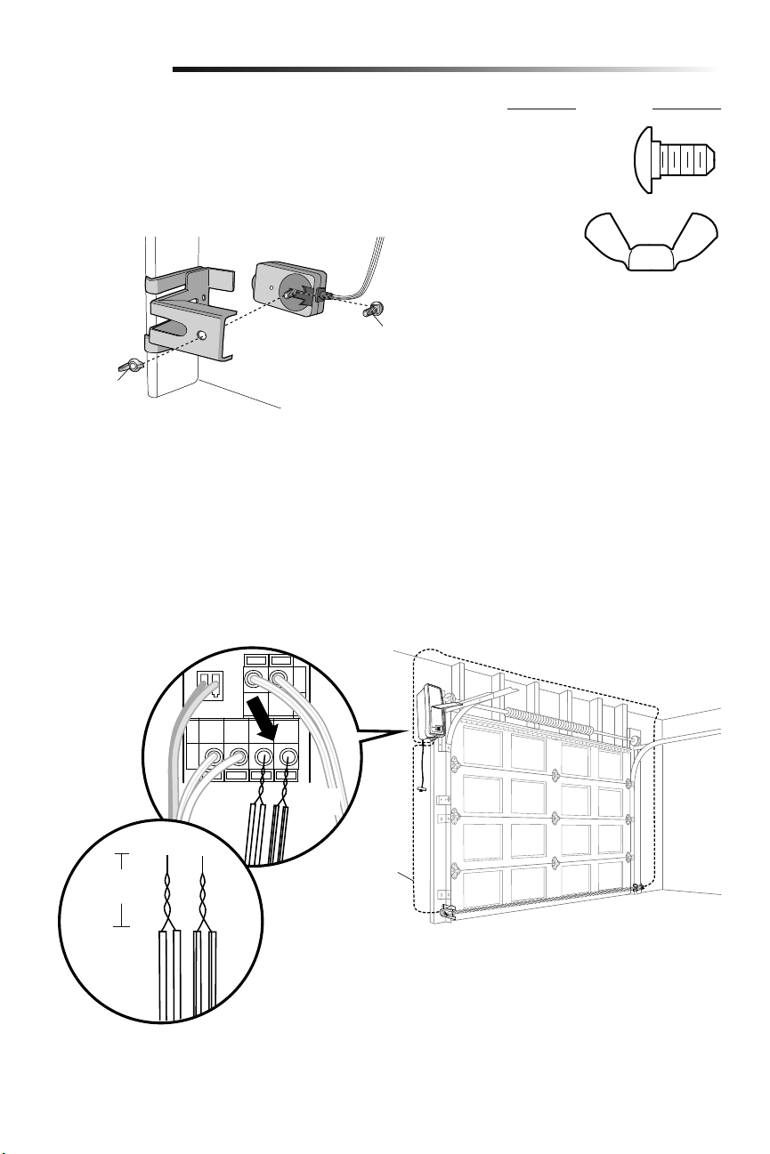
15
Instalación
CABLERO DE SENSOR DE SEGURIDAD DE REVERSA
1. Instale los cables desde los sensores hasta el abre-puertas de garaje. Fije los cables
a la pared y el techo con grapas.
2. Quitar 11 mm (7/16 de pulg.) de aislamiento de un extremo del cable. Separar los
cables. Retuerza juntas las cables blancos. Retuerza juntas las cables blancos/
negros.
3. Conectar los cables blanco a las terminales blancas del abre-puertas de garaje.
Conectar los cables blanco/negro a los terminales gris del abre-puertas de garaje.
Para conectar o desconectar un cable, empujar la pestaña con la punta de un
destornillador.
11 mm
(7/16 de pulg.)
BLANCO/
NEGRO
Cable del
timbre
BLANCO
MONTAJE Y CABLEADO DE LOS SENSORES DE SEGURIDAD DE REVERSA
1. Deslice un perno de coche de 1/4 de pulg. de 20x1/2 de pulg. en la ranura
de cada sensor.
2. Utilice tuercas mariposa para sujetar los sensores de reversa de seguridad a los
soportes, de modo que los cristales se enfrenten de un extremo al otro de la puerta.
Asegúrese de que las extensiones de soporte no obstruyan el cristal.
3. Apriete con los dedos las tuercas mariposa.
HERRAJES
Perno de coche
Tuerca
mariposa
Tuerca
mariposa
1/4 de pulg.-
20 (2)
Perno de coche de
1/4 de pulg.-20x1/2
de pulg. (2)
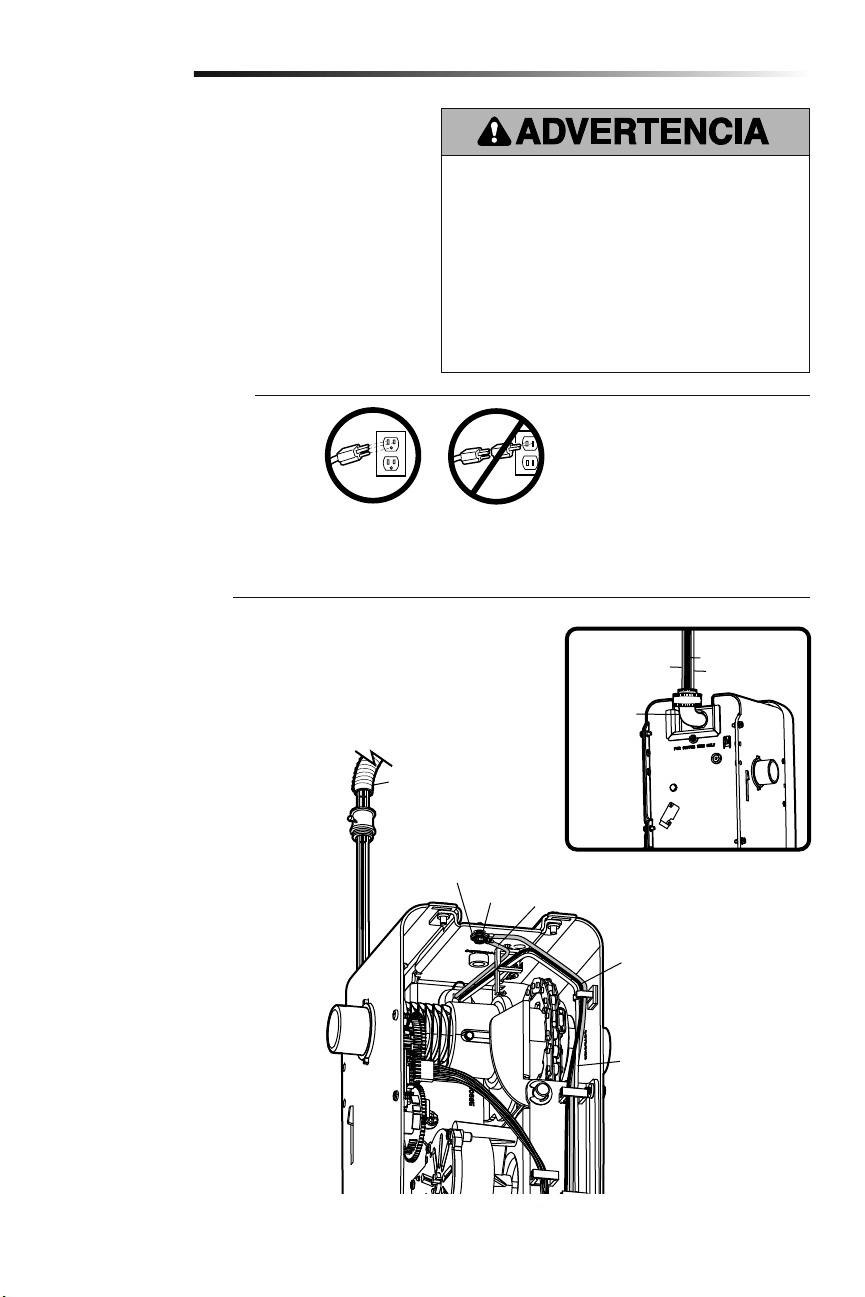
16
Conectar la alimentación
8
Instalación
OPCIÓN B: CONEXIÓN DEL CABLEADO
PERMANENTE
Si la reglamentación local exige que su
abre-puertas tenga cableado permanente,
siga los siguientes pasos.
Para hacer una conexión permanente a través
de la entrada de 7/8 de pulg. en la parte de
atrás del abre-puertas de garaje (según las
normas municipales vigentes):
1. Verifique que la energía NO esté
conectada al abre-puerta y desconecte la
alimentación eléctrica al circuito.
2. Desmontar el abre-puertas de garaje de
la barra de torsión, quitar los tornillos de
la tapa y hacerla a un lado.
3. Corte el cable 15.2 cm (6 pulg.) por
encima del aliviador de tensión.
4. Empuje el aliviador de tensión dentro
de la unidad de motor, luego retire el
aliviador de tensión del cable.
5. Instale un conducto de 90° (no incluido)
o un adaptador de cable flexible (no
incluido) en el orificio de 2.22 cm (7/8
de pulg). Vuelva a unir el abre-puertas
de garaje a la barra de torsión.
6. Pase los cables por el conducto, córtelos
a la medida correspondiente y quite el
aislamiento.
7. Pele 1.3 cm (1/2 de pulg.) de
aislamiento de los cables negro, blanco
y verde existentes.
8. Conecte la línea al cable negro y el
neutro al cable blanco con tuercas para
cables (no incluidas). Conecte el cable
de puesta a tierra al tornillo verde de
puesta a tierra.
9. Asegure los cables adecuadamente con
bridas de plástico para que no entren en
contacto con partes móviles.
10. Reinstale la cubierta.
Para evitar la posibilidad de una LESIÓN GRAVE o incluso LA
MUERTE por electrocución o incendio:
• Asegúrese de que el abre-puertas NO esté conectado a
la energía eléctrica y desconecte la alimentación eléctrica
al circuito ANTES de quitar la cubierta para establecer la
conexión del cableado permanente.
• Tanto la instalación como el cableado de la puerta de garaje
DEBEN cumplir con la reglamentación local eléctrica y de
construcción.
• NUNCA use una extensión ni un adaptador de dos cables;
tampoco modifique la clavija para poder enchufarla.
Asegúrese de que el abre-puertas esté puesto a tierra.
NOTA IMPORTANTE: Si no hubiera un
tomacorriente cerca del abre-puertas
de garaje puede usarse una fuente de
alimentación modelo 580LM. Los controles
de luz myQ continuarán funcionando,
pero los demás dispositivos myQ y el
temporizador de cierre no funcionarán con
la fuente de alimentación Modelo 580LM.
Para poder usar estos dispositivos haga
colocar un tomacorriente cerca del abre-
puertas de garaje.
Para evitar problemas con la instalación, no opere
el abre-puertas de garaje ahora.
Para reducir el riesgo de choque eléctrico, su abre-puertas de
garaje viene con un enchufe de conexión a tierra de tres clavijas.
Esta clavija sólo se puede conectar a una toma de corriente puesta
a tierra y con tres entradas. Si el enchufe no entra en la toma de
corriente que usted tiene, diríjase a un electricista profesional para
que instale la toma de corriente correcta.
Hay dos opciones para conectar la alimentación
eléctrica:
OPCIÓN A: CONEXIÓN TÍPICA
1. Enchufe el abre-puertas de garaje a un
tomacorriente con puesta a tierra.
2. Por el momento NO haga funcionar
el abre-puertas de garaje.
Terminal de
puesta a tierra
Tornillo verde
de puesta
a tierra
Cable de puesta a tierra
Cable negro de energía
Cable blanco de energía
Conduit flexible
Conector
de 90°
(No
Incluida)
Cable verde
Cable blanco
Cable negro
VISTA
TRASERA
INCORRECTOCORRECTO
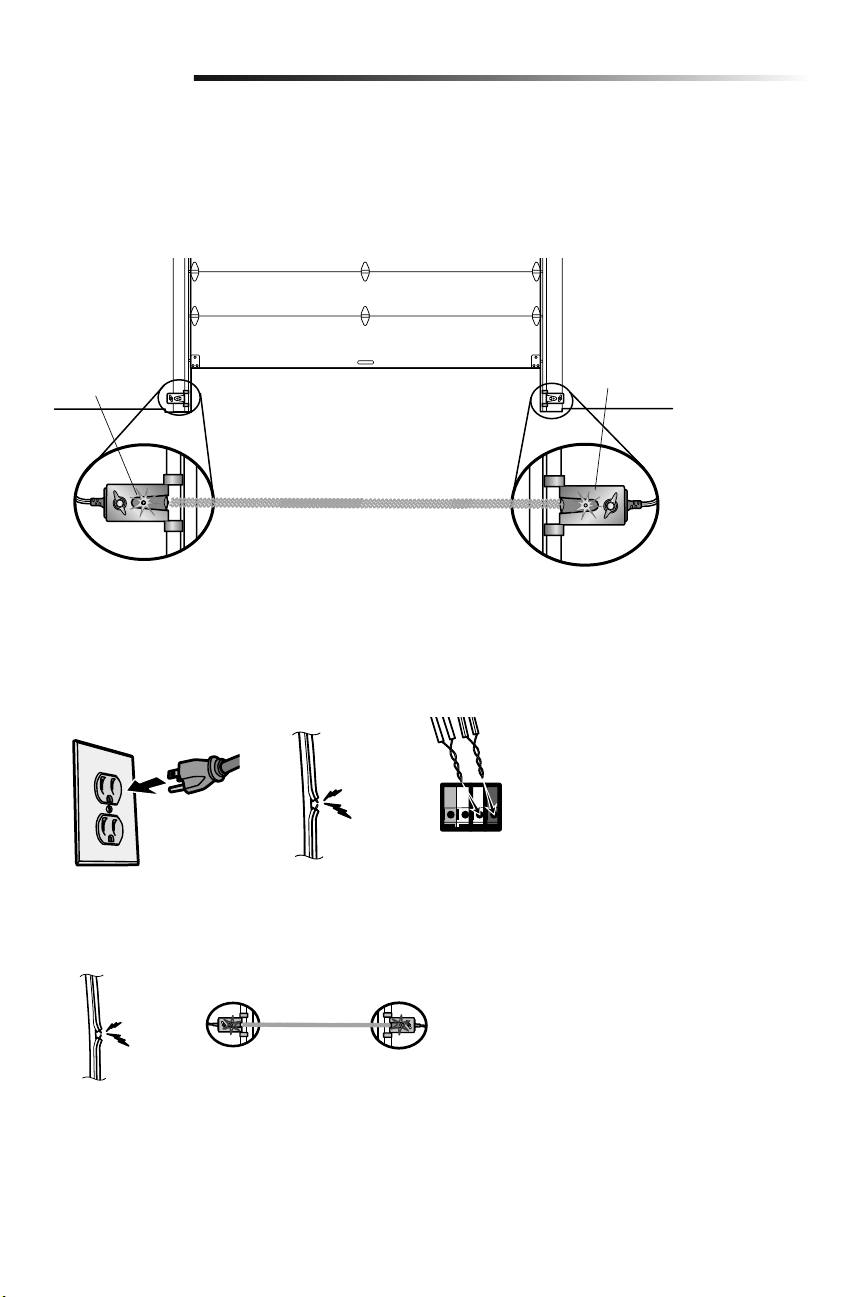
17
Sensor receptor
Verde
DEL
Sensor emisor
Ámbar
DEL
Instalación
SI EL LED ÁMBAR DEL SENSOR EMISOR NO SE ENCENDIERA:
• Verificar que llegue energía al abre-puertas de garaje.
• Verificar que no haya un cortocircuito ni el sensor esté roto.
• Verificar que el sensor esté correctamente conectado: cables blancos al terminal
blanco y cables blanco/negro al terminal gris.
Si el sensor receptor está expuesto
directamente a la luz solar, invertir la
conexión con el sensor del lado
opuesto.
(haz de luz invisible)
ALINEACIÓN DE LOS SENSORES DE SEGURIDAD
La puerta no se cerrará si los sensores de inversión no están instalados y alineados.
Si el haz de luz está desalineado o hay una obstrucción cuando la puerta se está cerrando,
la misma invertirá su dirección y las luces se encenderán y apagarán diez veces. Si la
puerta estuviera abierta, no se cerrará. Para alinear los sensores, aflojar las tuercas
mariposa, alinearlos y volver a ajustar las tuercas.
1.
Verificar que los LED de los sensores estén encendidos. Si los sensores están
conectados y alineados correctamente, los LED quedarán encendidos.
VERIFICAR QUE EL INSTALACIÓN DE ALAMBRES PARA EL CONTROL
REMOTO ES CORRECTAMENTE
La DEL amarillo de comando y la DEL rojo de aprendizaje en el control de puerta
parpadearán rápidamente hasta por 5 minutos mientras el control se carga. Con el control
en funcionamiento, la DEL amarillo de comando quedará encendido.
SI EL LED VERDE DEL SENSOR RECEPTOR NO SE ENCENDIERA:
• Verificar que no haya un cortocircuito ni el sensor esté roto.
• Verificar la alineación de los sensores.
ROJO
BLANCO
BLANCO
GRIS

18
En modo de reserva de batería, los dispositivos inalámbricos myQ y el temporizador
de cierre quedarán desactivados.
Si la reserva de batería (opcional) es parte del sistema, instalarla ahora. La reserva
de batería puede montarse en el techo o en la pared a una distancia máxima de 0.9 m
(3pies) del abre-puertas de garaje.
1.
Desenchufar el abre-puertas de garaje.
2. Montar la reserva de batería en un soporte estructural tal como una viga o un
travesaño de pared.
3. Fijar la reserva de batería con los dos tornillos tirafondos de 1-1/2 de pulg. que se
suministran. A ambos lados de la reserva de batería hay orificios de montaje.
4. Conectar el cordón al conector ubicado en la parte inferior del abre-puerta.
5. Siga todas las instrucciones de la reserva de batería para probar la unidad.
Instalar la batería de reserva (opcional)
9
Instalación
Cable de la batería
de reserva
475LM Reserva de batería
Conector

19
NEGRO
NEGRO
NEGRO
ALTO
NEGRO
AMARILLO
AMARILLO
AMARILLO
AMARILLO
Los límites del recorrido regulan los puntos en los que la puerta se detendrá al abrirse
y cerrarse.
Regule la posición de la puerta con los botones negro y amarillo. El negro mueve la puerta
hacia ARRIBA (apertura) y el amarillo la mueve hacia ABAJO (cierre).
NOTA: La DEL amarillo de comando y la DEL rojo de aprendizaje parpadearán rápidamente
hasta por 5 minutos mientras el panel de control se carga. Con el panel de control en
funcionamiento, la DEL amarillo de comando quedará encendido.
AJUSTE DE LA POSICIÓN ARRIBA:
1. Oprima y mantenga oprimido el botón negro hasta que la DEL (luz indicadora)
comience a parpadear lentamente, luego suéltelo.
2. Oprima y mantenga oprimido el botón negro hasta que la puerta alcance la posición
ARRIBA (abierta) deseada.
NOTA: Verifique que la puerta se abra lo suficiente para que pase su vehículo.
3. Oprima la control de la puerta o control remoto programado. Esto fija el límite
ARRIBA (abierta) y comienza a cerrar la puerta.
4.
Cuando la puerta comienza a cerrarse, pulse inmediatamente el botón negro o el
amarillo. La puerta se detendrá.
AJUSTE DE LA POSICIÓN ABAJO:
5. Mantener oprimido el botón amarillo hasta que la puerta alcance la posición deseada
de ABAJO (cierre).
6. Si pareciera haber demasiada presión sobre la puerta cerrada, puede moverla hacia
arriba y abajo con los botones negro y amarillo hasta alcanzar la posición deseada.
7. Oprima la control de la puerta o control remoto programado. Esto fija el límite ABAJO
(cerrada) y debe mover la puerta hacia la posición abierta.
Proceda al Ajustar la fuerza.
Programación de los límites del recorrido
Ajustes
1
2
Si el sistema de reversa de seguridad
no se ha instalado debidamente, las
personas (y los niños pequeños en
particular) podrían sufrir LESIONES
GRAVES o incluso LA MUERTE cuando
se cierre la puerta del garaje.
• NUNCA programe fuerzas o límites
si la puerta está atorada o atascada.
Primero, repare la puerta.
• El ajuste incorrecto de los límites
del recorrido de la puerta del garaje
habrá de interferir con la operación
adecuada del sistema de reversa de
seguridad.
• Después de llevar a cabo cualquier
ajuste, se DEBE probar el sistema
de reversa de seguridad. La puerta
DEBE retroceder al entrar en contacto
con un objeto de 3.8 cm (1-1/2 de
pulg.) de altura (o un tablón de 2x4
acostado) que se coloque en el suelo.
Para evitar que los vehículos sufran
daños, asegúrese de que, cuando la
puerta esté completamente abierta,
quede suficiente espacio libre.
1
DEL
o
o
o
3
7456
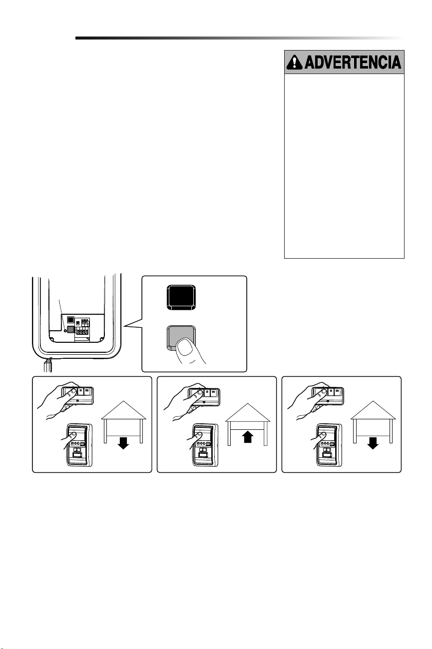
20
NEGRO
AMARILLO
El ajuste de la fuerza mide la cantidad de fuerza necesaria para abrir y cerrar la
puerta.
1. Pulse dos veces el botón amarillo para pasar al modo de Regulación de fuerza. La
DEL parpadeará rápidamente.
2.
Oprima la control de la puerta o control remoto programado. La puerta se moverá
hasta la posición ABAJO (cerrada).
3. Oprima la control de la puerta o control remoto programado nuevamente y la puerta
se moverá hasta la posición ARRIBA (abierta).
4. Oprima la control de la puerta o control remoto programado por tercera vez para
enviar la puerta a la posición ABAJO (cerrada).
La DEL (Luz Indicadora) dejará de parpadear cuando la fuerza se haya programado.
La puerta debe recorrer un ciclo completo, arriba y abajo, para que la fuerza se
ajuste adecuadamente. Si abre-puertas de garaje no puede abrir ni cerrar su puerta
completamente, inspeccione su puerta para asegurarse de que esté bien equilibrada y no
esté atascada ni atorada.
Si la puerta no se detiene exactamente donde usted quiere, repita Programación de los
límites del recorrido.
Ajustar la fuerza
Si el sistema de reversa de seguridad
no se ha instalado debidamente, las
personas (y los niños pequeños en
particular) podrían sufrir LESIONES
GRAVES o incluso LA MUERTE cuando
se cierre la puerta del garaje.
• NUNCA programe fuerzas o límites
si la puerta está atorada o atascada.
Primero repare la puerta.
• Si el límite de la fuerza del abre-
puertas de garaje es excesivo,
habrá de interferir con la operación
adecuada del sistema de reversa de
seguridad.
• Después de llevar a cabo cualquier
ajuste, se DEBE probar el sistema
de reversa de seguridad. La puerta
DEBE retroceder al entrar en contacto
con un objeto de 3.8 cm (1-1/2 de
pulg.) de altura (o un tablón de 2x4
acostado) que se coloque en el suelo.
2
Ajustes
1
DEL
o o o
423
Pulse dos
veces el botón
amarillo para
pasar al modo
de Regulación
de fuerza
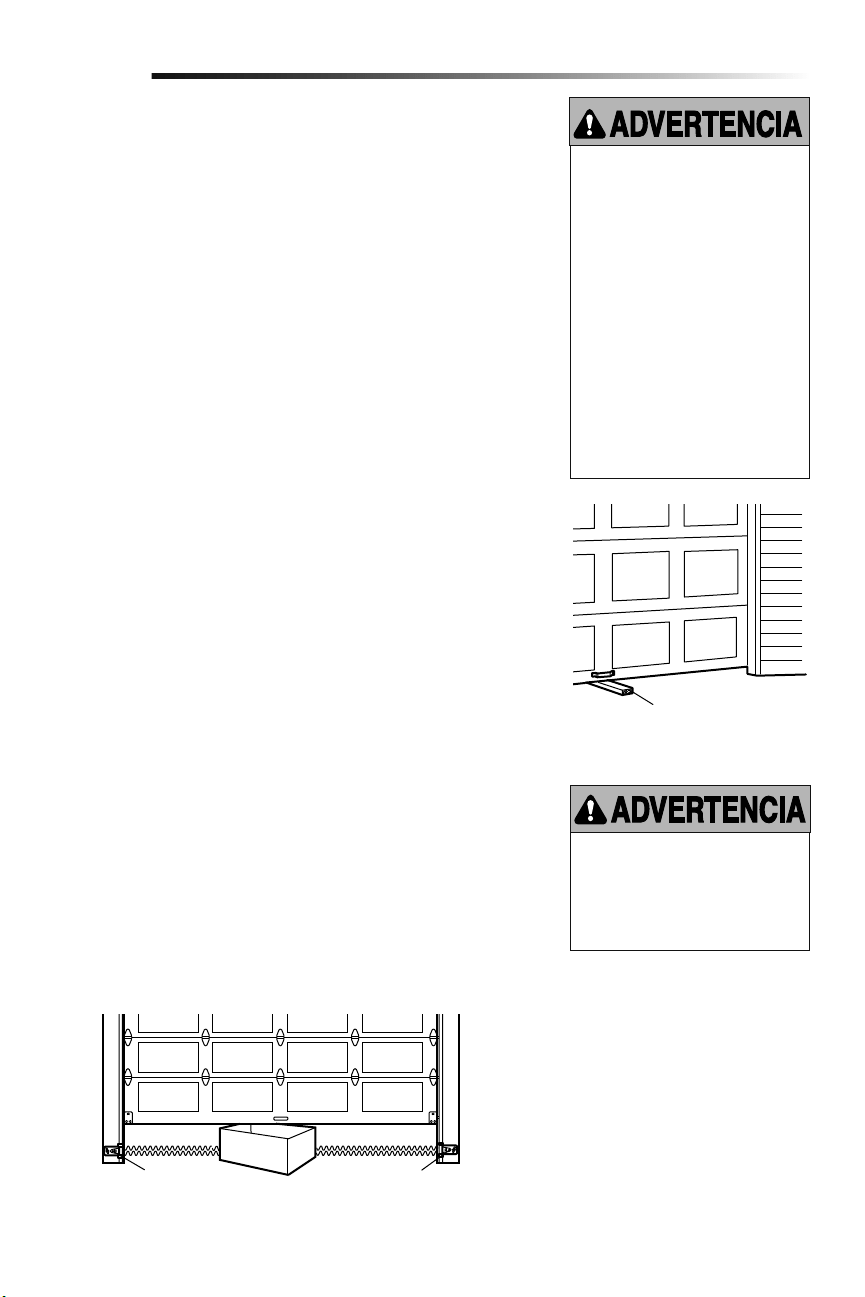
21
PRUEBA
1. Con la puerta totalmente abierta, coloque un tablón de 3.8 cm (1-1/2 de pulg.) (o de
2 x 4 acostado) en el suelo, centrado debajo de la puerta del garaje.
2. Opere la puerta en la dirección hacia abajo. La puerta debe retroceder al entrar en
contacto con la obstrucción. Una vez que haya realizado una prueba exitosa del
sistema de reversa de seguridad, proceda al Paso 4 de la sección de Ajustes.
AJUSTE
Si la puerta se detiene al entrar en contacto con la obstrucción, esto significa que el
recorrido hacia abajo no es suficiente. Complete los Pasos 1 y 2 de la sección de Ajustes,
Programación de los límites del recorrido y Ajustar la fuerza.
Repita la prueba.
Cuando la puerta retroceda al entrar en contacto con el tablón de 3.8 cm (1-1/2 de pulg.)
(o de 2x4 acostado), quite la obstrucción y opere el abre-puertas de garaje para que
realice 3 ó 4 ciclos completos de operación a fin de probar el ajuste.
Si el abre-puertas de garaje no pasa la prueba de seguridad de inversión de marcha llamar
a un técnico profesional.
VERIFICACIÓN IMPORTANTE DE SEGURIDAD:
Pruebe el Sistema de reversa de seguridad luego de:
• Cada ajuste de límites o de controles de fuerza.
• Cualquier reparación o ajuste a la puerta del garaje (incluidos los resortes y las
piezas).
• Cualquier reparación al suelo del garaje porque esté desnivelado, etc.
• Cualquier reparación o ajuste al abre-puertas.
Prueba del sistema de seguridad de reversa
Prueba del Protector System
®
1. Oprima el botón del control remoto para abrir la puerta.
2. Coloque la caja del abre-puertas en el trayecto de la puerta.
3. Oprima el botón del control remoto para cerrar la puerta. La puerta no se moverá
más de 2.5 cm (una pulg.), y las luces del abre-puertas parpadearán.
El abre-puertas del garaje no se cerrará con un control remoto si la luz indicadora de
cualquiera de los sensores está apagada(lo cual le indica que el sensor esta desalineado
u obstruido).
Si el abre-puertas de garaje cierra la puerta cuando el sensor de reversa de seguridad
está obstruido, no opere la puerta. Llame a un técnico especializado en sistemas de
puertas.
Si el sistema de reversa de seguridad
no se ha instalado debidamente, las
personas (y los niños pequeños en
particular) podrían sufrir LESIONES
GRAVES o incluso LA MUERTE cuando
se cierre la puerta del garaje.
• El sistema de reversa de seguridad se
DEBE probar cada mes.
• Si se ajusta uno de los controles
(límites de la fuerza o del recorrido),
es posible que sea necesario ajustar
también el otro control.
• Después de llevar a cabo cualquier
ajuste, se DEBE probar el sistema
de reversa de seguridad. La puerta
DEBE retroceder al entrar en contacto
con un objeto de 3.8 cm (1-1/2 de
pulg.) de altura (o un tablón de 2x4
acostado) que se coloque en el suelo.
Si el sistema de reversa de seguridad
no se ha instalado debidamente, las
personas (y los niños pequeños en
particular) podrían sufrir LESIONES
GRAVES o incluso LA MUERTE cuando
se cierre la puerta del garaje.
3
4
Ajustes
Tablón de 3.8 cm (1-1/2 de pulg.)
(o de 2X4, acostado)
Sensor de seguridad de reversa Sensor de seguridad de reversa
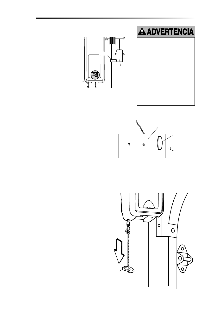
22
1. Cuando la puerta esté totalmente cerrada, el perno del seguro
de puerta eléctrico debe sobresalir a través de la guía.
2. Opere la puerta en la dirección hacia arriba. El seguro de
puerta eléctrico debe replegarse antes de que la puerta
comience a moverse.
3. Opere la puerta en la dirección hacia abajo. Cuando la puerta
alcance la posición totalmente cerrada, el seguro de puerta
eléctrico debe activarse automáticamente para asegurar la
puerta.
NOTA: Si el seguro de puerta eléctrico no funciona, puede
desengancharse manualmente moviendo la manija de
desenganche manual hacia la posición abierta.
Desactive el seguro de puerta antes de continuar. Si es posible,
la puerta se debe cerrar completamente. Jale la manija de
desenganche de emergencia hasta que escucharán un clasquido
de unidad y levante la puerta manualmente.
Para volver a conectar el abre-puertas de garaje tirar de la manija
de apertura de emergencia directamente hacia abajo hasta que se
escuche un clic en el abre-puertas de garaje. La puerta se volverá
a conectar la próxima vez que la accione hacia ARRIBA o hacia
ABAJO.
Prueba del desenganche de emergencia:
1. Asegúrese de que la puerta del garaje esté cerrada.
2. Jale la manija del desenganche de emergencia. La puerta del
garaje debe poder abrirse manualmente.
3. Regrese la puerta a la posición cerrada.
4. Jale la manija de emergencia por segunda vez.
5. Vuelva a conectar la puerta al abre-puertas de garaje.
Prueba del monitor de tensión del cable
Prueba del seguro de puerta eléctrico
Cómo abrir la puerta manualmente
5
6
7
Ajustes
Para evitar la posibilidad de una
LESIÓN GRAVE o incluso LA MUERTE
si la puerta del garaje se cae:
• Si es posible, utilice la manija de
desenganche de emergencia para
desenganchar la puerta SÓLO cuando
la puerta del garaje esté CERRADA. Si
los resortes están débiles o rotos, o
bien si la puerta está desequilibrada y
se abre, ésta podría caerse rápida y/o
inesperadamente.
• NUNCA use la manija de desenganche
de emergencia a menos que la
entrada al garaje esté libre de
obstrucciones y no haya ninguna
persona presente.
Seguro eléctrico
Desenganche
manual
Perno del
seguro
“Cerrado”
Manija de
desenganche
de emergencia
1. Con la puerta completamente cerrada,
empuje en la parte frontal del monitor
de tensión del cable. Un clic debe ser
oído. Si no oye ningún clic, el rodillo
puede estar golpeando el montante
y no permitir que el interruptor
detecte aflojamiento de en el cable.
Asegúrese de que el monitor de
tensión del cable está montado a ras
de la pared y el rodillo está libre de
cualquier obstrucción.
Si su monitor de tensión del cable se ha
activado, la DEL (Luz Indicadora) va a
parpadear 9 veces.
DEL
Rodillo
Monitor de
tensión del
cable

23
Operación
INSTRUCCIONES DE SEGURIDAD IMPORTANTES
Para reducir el riesgo de
LESIONES GRAVES o de MUERTE:
1. Lea y respete TODAS las advertencias y las instrucciones.
2. SIEMPRE conserve los controles remotos lejos del alcance
de los niños. NUNCA permita que los niños operen o jueguen
con los botones del control del abre-puertas de garaje ni con
los controles remotos.
3. SÓLO active el abre-puertas de garaje siempre y cuando lo
puedan ver con claridad, esté debidamente ajustado y no
haya ninguna obstrucción en su recorrido al cerrarse.
4. SIEMPRE mantenga a la puerta de garaje hasta que
esté totalmente cerrada. NADIE DEBE ATRAVESAR
EL RECORRIDO DE LA PUERTA CUANDO ESTÁ EN
MOVIMIENTO.
5. NADIE DEBE CRUZAR POR DEBAJO DE UNA PUERTA
DETENIDA O PARCIALMENTE ABIERTA.
6. De ser posible, use el desenganche de emergencia
para soltar el carro SÓLO cuando la puerta del garaje
esté CERRADA. Tenga precaución cuando utilice este
desenganche con la puerta abierta. Los resortes débiles o
rotos o la puerta desequilibrada pueden ocasionar que una
puerta abierta caiga rápida y/o inesperadamente y aumentan
el riesgo de LESIONES GRAVES o la MUERTE.
7. NUNCA use la manija del desenganche de emergencia a
menos que la entrada al garaje esté libre de obstrucciones y
no haya ninguna persona presente.
8. Después de llevar a cabo cualquier ajuste, se DEBE probar
el sistema de seguridad de reversa. El ajuste y la regulación
incorrectas de la abre-puertas de garaje puede causar
GRAVES LESIONES e INCLUSO LA MUERTE.
9. El sistema de reversa de seguridad SE DEBE probar cada
mes. La puerta DEBE retroceder al entrar en contacto con
un objeto de 3.8 cm (1-1/2 de pulg.) de altura (o un tablón
de madera de 2 X 4) acostado en el piso. El ajuste y la
regulación incorrectas de la abre-puertas de garaje puede
causar GRAVES LESIONES e INCLUSO LA MUERTE.
10. MANTENGA SIEMPRE LA PUERTA DEL GARAJE
DEBIDAMENTE EQUILIBRADA (vea la página 4). Si la puerta
no está debidamente equilibrada es posible que NO retroceda
cuando así se requiera y podría ocasionar una LESIÓN
GRAVE o incluso LA MUERTE.
11. TODAS las reparaciones necesarias para los cables, resortes
y otras piezas las DEBE llevar a cabo un técnico profesional
en sistemas de puertas, pues TODAS estas piezas están bajo
una tensión EXTREMA.
12. Para evitar LESIONES PERSONALES GRAVES o la MUERTE
por electrocución, desconectar TOTALMENTE la energía
eléctrica y de la batería ANTES de hacer CUALQUIER trabajo
de reparación o mantenimiento.
13. Este sistema tiene una función de activación por estado
pasivo. La puerta podría ponerse en movimiento
repentinamente. NADIE DEBE ATRAVESAR EL RECORRIDO
DE LA PUERTA CUANDO ESTÁ EN MOVIMIENTO.
14.
CONSERVE ESTAS
INSTRUCCIONES.
El abre-puertas de garaje ya viene
programado de fábrica para funcionar con
el control remoto, que cambia cada vez
que se usa y puede acceder aleatoriamente
a más de cien mil millones de código
nuevos. La tecnología myQ utiliza señal
de 900 MHz para comunicaciones
bidireccionales entre el abre-puertas
de garaje y los accesorios compatibles
con myQ. Cuando está programado con
el LiftMaster
®
Internet Gateway, usted
puede monitorear y controlar la puerta de
su garaje desde cualquier computadora
o Smartphone con conexión a Internet.
Es posible programar hasta 12 controles
remotos Security+2.0
®
, 2 entradas sin
llave Security+ 2.0
®
y una combinación de
16 accesorios myQ conectados al panel de
control myQ.
El abre-puertas de garaje puede activarse
con un control fijo montado en la pared,
un control remoto, una llave digital o un
accesorio myQ. Al activarse el abre-puertas
de garaje con la puerta cerrada, la puerta se
abrirá. Si la puerta detecta una obstrucción
o se interrumpe durante la apertura, la
puerta se detendrá. Si la puerta se ha
Uso del abre-puertas de garaje
detenido en cualquier posición que no sea
cerrada, al activar el abre-puertas de garaje
la misma se cerrará. Si el abre-puertas de
garaje detecta una obstrucción mientras se
cierra, la puerta invertirá su dirección de
movimiento. Si una obstrucción interrumpe
el haz del sensor, las luces del abre-
puertas de garaje parpadearán 10 veces.
Sin embargo, puede cerrar la puerta si
mantiene presionado el botón del control
o de la llave digital hasta que la puerta
se cierre por completo. Los sensores de
reversa de seguridad no afectan el ciclo de
apertura. El sensor de reversa de seguridad
debe estar bien conectado y alineado antes
de que el abre-puertas de garaje se mueva
hacia abajo.
Las luces de abre-puertas de garaje se
encenderán al activarse el abre-puertas
de garaje. Se apagarán automáticamente
después de 4-1/2 minutos o se quedarán
encendidas si se activa la función de luz en
el panel de control myQ. El tamaño de la
lámpara es A19. La potencia máxima de la
lámpara debe ser de 100 vatios.
Característica luces: Las luces también se
encenderán si alguien camina a través de la
puerta del garaje. Con un panel de control
myQ, esta función puede desactivarse
de la siguiente manera: Con las luces de
abre-puertas de garaje apagadas, pulse el
botón de luz durante 10 segundos hasta
que las luces se enciendan y se apaguen
nuevamente. Para restituir esta función:
con las luces encendidas, pulse el botón
de luz durante 10 segundos hasta que se
apaguen y se enciendan nuevamente.
TEMPORIZADOR DE CIERRE (TTC)
El temporizador de cierre cierra
automáticamente la puerta después de
cierto tiempo, el cual puede ser regulado
con el control de puerta. Antes y durante el
cierre de la puerta, las luces parpadearán y
se escuchará una señal sonora.
RESERVA DE BATERÍA*
El sistema de reserva de la batería permite
ingresar y salir del garaje, aun cuando no
haya energía eléctrica. Cuando el abre-
puertas de garaje funciona a batería será
más lento, las luces no funcionarán, la
DEL de estado de batería se encenderá de
color anaranjado y se escuchará una señal
sonora cada dos segundos.
* Si corresponde.
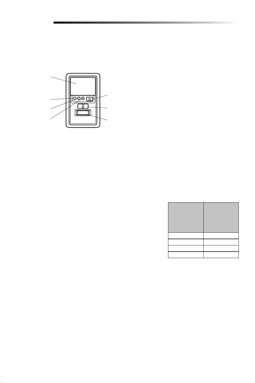
24
Operación
Uso del control de puerta (Panel de control myQ)
NOTA: Por el consumo de energía, este control de puerta (Modelo 889LM) no puede usarse con ningún otro control cableado conectado
al abre-puertas de garaje. Si fuera necesario otro control de puerta, el modelo inalámbrico 885LM puede programarse con el control de
puerta (Modelo 889LM). Para programar el 885LM con el panel de control myQ, siga los pasos de programación del control remoto.
NOTA: En modo de reserva de batería, los controles de luz myQ continuarán funcionando, pero los demás dispositivos myQ y el
temporizador de cierre no funcionarán con la fuente de alimentación Modelo 580LM.
Botón "LIGHT" (LUZ)
Botón "HOLD OPEN"
(MANTENER ABIERTA)
Sensor de movimiento
Barra de empuje
DEL TTC 1 minuto
DEL TTC 5 minutos
DEL TTC 10 minutos
botón HOLD OPEN (mantener abierta)
es oprima otra vez o el abre-puertas
de garaje se activa de otro dispositivo
(control de la puerta, control remoto,
llave digital, etcétera).
LUCES
Oprima el botón "LIGHT" para encender
o apagar las luces del abre-puertas de
garaje. Cuando se enciendan las luces,
permanecerán así hasta que se oprima
de nuevo el botón "LIGHT" o hasta que se
active el abre-puertas de garaje. Una vez
que el abre-puertas de garaje se active, las
luces se apagarán después del período de
tiempo especificado (el ajuste de fábrica
es de 4-1/2 minutos). El botón "LIGHT" no
controlará las luces cuando la puerta esté
en movimiento.
Para cambiar el tiempo que permanecerán
encendidas las luces del abre-puertas de
garaje:
Mantenga oprimido el botón "LOCK" hasta
que las luces del abre-puertas de garaje
parpadeen. El intervalo de tiempo será
indicado por la cantidad de parpadeos.
CANTIDAD DE
VECES QUE
PARPADEAN
LAS LUCES DEL
ABRE-PUERTAS
DE GARAJE
TIEMPO QUE
PERMANECEN
ENCENDIDAS
LAS LUCES DEL
ABRE-PUERTAS
DE GARAJE
1 1 ½ Minutos
2 2 ½ Minutos
3 3 ½ Minutos
4 4 ½ Minutos
Funcionalidad de las luces
Las luces se encenderán cuando alguien
entre por la puerta del garaje abierta y se
interrumpa el haz infrarrojo del sensor de
inversión.
Activar:
Comience con las luces del abre-
puertas de garaje encendidas.
Mantenga oprimido el botón
"LIGHT" hasta que se apaguen las
luces del abre-puertas de garaje; a
continuación, enciéndalas de nuevo.*
Desactivar:
Mantenga oprimido el botón
"LIGHT" hasta que se enciendan las
luces del abre-puertas de garaje; a
continuación, apáguelas de nuevo.*
* Aproximadamente 10 segundos
BARRA DE EMPUJE
Presione la barra de empuje para abrir/
cerrar la puerta.
LOCK ("SEGURO")
Esta función está diseñada para evitar la
operación de la puerta con los controles
remotos manuales. No obstante, la puerta
se puede abrir y cerrar con los siguientes
accesorios: el Control de la puerta, el
Interruptor de llave externo, la llave digital,
y LiftMaster
®
Internet Gateway.
Activar:
Mantenga oprimido el botón "LOCK"
durante 2 segundos. La DEL de
comando parpadeará mientras esté
activado el seguro y su control remoto
portátil no operará la puerta en este
momento.
Desactivar:
Mantenga oprimido de nuevo el botón
"LOCK" durante 2 segundos. La DEL
de comando dejará de parpadear y se
reanudará la operación normal.
SENSOR DE MOVIMIENTO
Esta funcionalidad encenderá
automáticamente las luces del abre-puertas
de garaje cuando se detecte movimiento.
Las luces se encenderán durante 4-1/2
minutos y luego se apagarán.
Activar/Desactivar:
Deslice el selector del sensor de
movimiento hacia ACTIVADO u
DESACTIVADO.
TEMPORIZADOR DE CIERRE (TTC)
La función del TTC cerrará
automáticamente la puerta después de
un periodo de tiempo especificado (1, 5
o 10 minutos). Una vez que el TTC se ha
configurado y que la puerta está abierta,
la DEL del intervalo de cierre seleccionado
parpadeará y comenzará la cuenta
regresiva para cerrar la puerta. El panel de
control emitirá una señal sonora y las luces
del abre-puertas de garaje parpadearán
antes de cerrar la puerta.
La funcionalidad TTC se desactivará si
la puerta del garaje se encuentra dos
obstrucciones secuenciales, o si los
sensores de inversión de seguridad están
instalados incorrectamente. La puerta del
garaje invertirá su movimiento y se abrirá
y NO se cerrará hasta que se eliminen las
obstrucciones o se instalen correctamente
los sensores de inversión de seguridad.
Cuando la obstrucción haya sido eliminada
o se hayan alineado los sensores de
inversión de seguridad, la puerta se cerrará
al activar el abre-puertas de garaje.
Activar:
Mantenga oprimido el botón "ON"
hasta que se encienda uno de
los DEL del TTC. A continuación,
oprima de nuevo el botón "ON" para
desplazarse por las opciones de
intervalos de tiempo (la DEL del TTC
correspondiente se encenderá para
cada intervalo de tiempo). Los focos
de las luces del abre-puertas de garaje
parpadearán a modo de confirmación.
Desactivar:
Mantenga oprimido el botón
"OFF" hasta que todos los DEL
TTC se apaguen y se oiga un tono
proveniente de la panel de control.
Para suspender el TTC (temporizador de
cierra):
Para suspender el temporizador
de cierre y mantener abierta
temporalmente la puerta, oprima
y suelte el botón HOLD OPEN
(mantener abierta) (el DEL de
HOLD OPEN [mantener abierta] se
encendida sólido). El temporizador de
cierre seguirá suspendido hasta que el
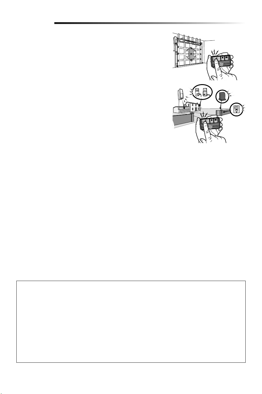
25
Operación
Cómo usar el control remoto
Mantenga oprimido el botón hasta que la puerta o barrera comience a moverse. En
instalaciones típicas, el control remoto podrá comandar la unidad a una distancia de hasta
tres veces la longitud del automóvil. Los tipos y las condiciones de instalación pueden
variar. Comuníquese con un distribuidor y servicio técnico para obtener más información.
Controles remotos de 3 botone
Es posible programar otros botones del control remoto para comandar hasta 3
dispositivos tales como otros abre-puertas de garaje, luces, barreras o sistemas de
control de ingreso.
ADVERTENCIA: Este dispositivo cumple con la Parte 15 de la reglamentación de la FCC y los estándares RSS exentos de licencia de Industry Canada. La
operación está sujeta a las dos condiciones siguientes:(1) este dispositivo no puede causar interferencia perjudicial, y (2) este dispositivo debe aceptar
cualquier interferencia recibida, incluyendo la interferencia que puede causar una operación no deseable.
Cualquier cambio o modificación no expresamente aprobada por la parte responsable del cumplimiento podría anular la autoridad del usuario para operar el
equipo.
Instalar este dispositivo de manera que quede una distancia mínima de 20 cm (8 pulg.) entre el dispositivo y los usuarios/transeúntes.
Este equipo ha sido verificado y cumple con los límites para un dispositivo digital de Clase B, conforme con la Parte 15 de las normas de la FCC y el estándar
ICES de Industry Canada. Estos límites se establecen para brindar un nivel razonable de protección contra interferencias perjudiciales en instalaciones
residenciales. Este equipo genera, usa y puede emitir energía de radiofrecuencia. Si no se instala y utiliza de acuerdo con las instrucciones podrá causar
interferencia con comunicaciones radiales. Aun así, no hay garantía de que no se produzcan interferencias en una instalación particular. Si este equipo
produce interferencia en la recepción de radio o televisión, lo cual puede determinarse apagando y encendiendo la unidad, el usuario debe tratar de corregir
el problema por medio de lo siguiente:
• Volver a orientar o reubicar la antena receptora.
• Aumentar la distancia entre el equipo y el receptor.
• Conectar el equipo en una salida de un circuito distinto del circuito al que está conectado el receptor.
• Consultar con el distribuidor o con un técnico de radio/TV experimentado para pedir ayuda.
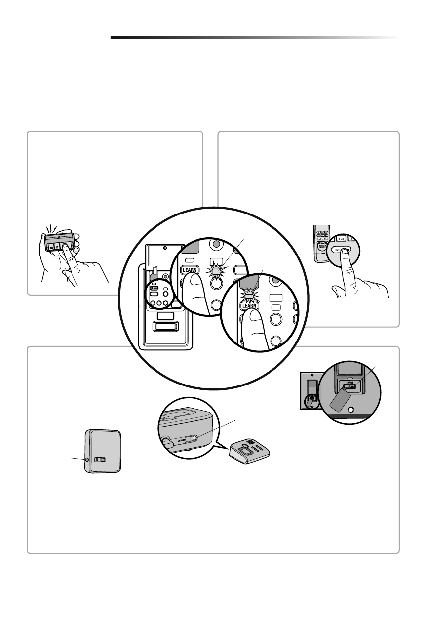
26
Programación
El control remoto modelo 893MAX está programado de fábrica con el control de puerta (Panel de control myQ). A continuación se
indican las instrucciones para programar con el control de puerta otros controles remotos, entradas sin llave y accesorios myQ.
NOTA: Para programar los accesorios usar el botón de aprendizaje del control de puerta. El botón amarillo de aprendizaje del abre-
puertas de garaje NO programará los accesorios.
Para agregar un control remoto, llave digital o accesorios compatibles con myQ con
el control de puerta (Panel de control myQ)
PIN
????
CONTROL REMOTO
1. Presione dos veces el botón PROGRAMAR (LEARN)
del panel de control myQ ; la DEL de programación
rojo se encenderá.
2. Presione el botón del control remoto con el cual
desea operar la puerta.
3. Las luces del abre-puertas de garaje parpadearán
(o se escucharán dos clics) cuando el código quede
programado.
1. Presione dos veces el botón PROGRAMAR (LEARN) del
panel de control myQ ; la DEL de programación rojo se
encenderá.
2. Escriba un número de cuatro dígitos (PIN) como código
personal de uso en el teclado de acceso con llave digital.
Luego, presione el botón ENTER.
3. Las luces del abre-puertas de garaje parpadearán (o
se escucharán dos clics) cuando el código quede
programado.
LLAVE DIGITAL
Botón
“LEARN”
Botón
“LEARN”
Modelo 825LM – Control remoto de
iluminación
El módulo de iluminación se puede
sincronizar con las bombillas del abre-
puertas de garaje.
Modelo 823LM – Interruptor remoto de
iluminación
El módulo de iluminación se puede
sincronizar con las bombillas del abre-
puertas de garaje.
Botón
“LEARN”
Modelo 829LM – Puerta de garaje y
monitoreo de la puerta
Indica el estado de su puerta del garaje
desde el interior de la casa y le permite
cerrar y abrir la puerta del garaje desde el
interior de la casa.
ACCESORIOS ACTIVADOS
myQ
1. Presione dos veces el botón
PROGRAMAR (LEARN)del panel de
control myQ; la DEL de programación
rojo se encenderá.
2. Presione el botón PROGRAMAR
(LEARN) en el dispositivo myQ.*
* Los accesorios myQ se pueden
programar con LiftMaster
®
Internet
Gateway (Modelo 828LM) o con el
panel de control myQ. Para las
instrucciones sobre la programación a
la puerta de entrada del Internet,
consulte el manual.
DEL de
comando (amarillo)
DEL de
programación
(rojo)
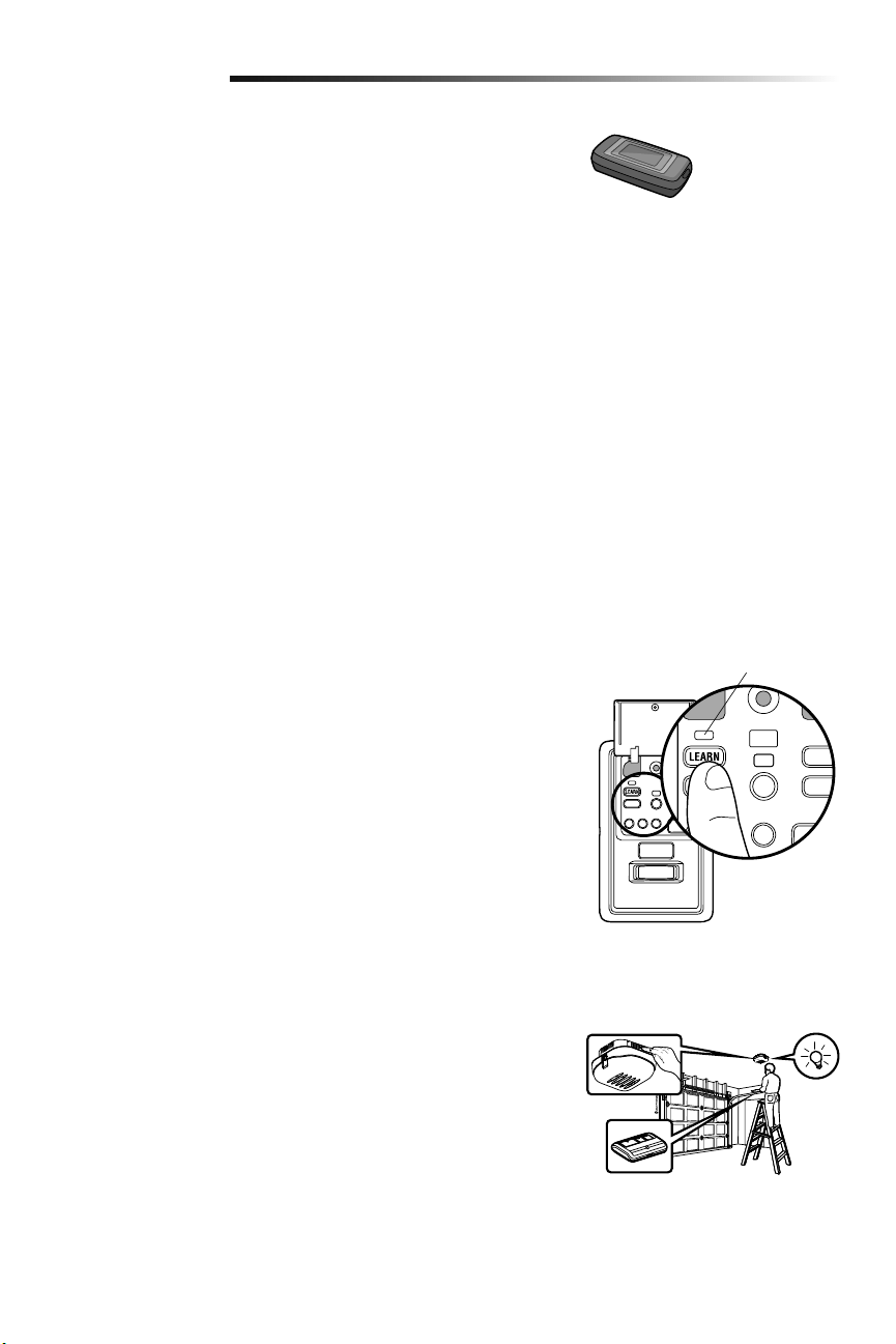
27
Programación
Internet Gateway LiftMaster
®
(No incluido)
El LiftMaster
®
Internet Gateway le da control de su puerta del garaje desde su
computadora o dispositivo móvil conectado a Internet.
Para programar el panel de control myQ
®
al Internet Gateway LiftMaster
®
:
1. Descargue la aplicación de myQ.
2. Configurar una cuenta y conectarse.
3. Seleccione “Internet Gateway” y siga las instrucciones de la aplicación.
IMPORTANTE: Se le indicará que presione el botón de “Aprendizaje” que está
ubicado en el panel de control myQ y deberá presionarlo 2 veces.
Para obtener más información sobre la conexión de su abre-puertas de garaje visite
LiftMaster.com/customer-support.
Modelo 828LM
LiftMaster
®
Internet
Gateway
Para eliminar todos los códigos de la memoria del
control de puerta (Panel de control myQ)
Borrar todos los datos de control remoto y llave digital:
1. Mantener oprimido el botón de "aprendizaje" (LEARN) en el panel de control hasta
que se apague la DEL (aproximadamente 6 segundos). Se borrarán todos los datos
almacenados en el control remoto y en la cerradura digital. Volver a programar todo
accesorio que desea usar.
Borrar todos los dispositivos (incluyendo los accesorios myQ):
1. Mantener oprimido el botón de "aprendizaje" (LEARN) en el panel de control hasta
que se apague la DEL (aproximadamente 6 segundos).
2. Inmediatamente pulsar el botón de "aprendizaje" (LEARN) hasta que la DEL se
apague. Ahora todos los códigos estarán borrados Volver a programar todo
accesorio que desea usar.
DEL de
programación
(rojo)
Cómo reprogramar la luz o luz adicional
La luz remota de su abre-puertas de garaje ya viene programada de fábrica para operar
con su abre-puertas. Todas luz remota adicionales o de reemplazo deberá programarse.
1. Oprima el botón de “aprendizaje” (LEARN) de la luz hasta que la DEL se ENCIENDA.
2. Activar el abre-puertas de garaje con el control remoto, con el control fijo o con el
teclado digital.
3. Cuando la luz se encienda significa que se ha registrado el código.
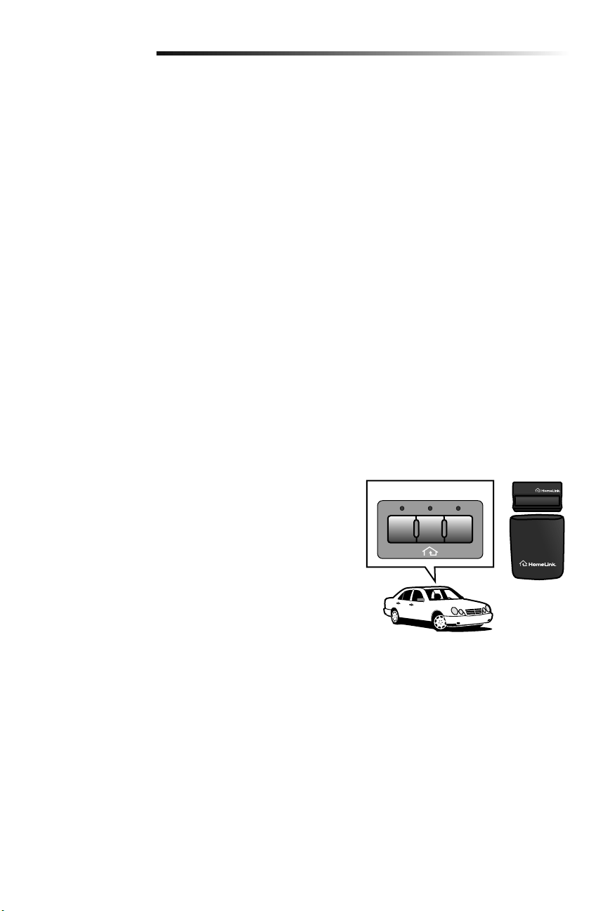
28
Programación
Programación adicional para la llave digital (no suministrada)
PARA CAMBIAR UNA CLAVE (PIN) EXISTENTE Y CONOCIDA
Si la clave (PIN) existente ya es conocida, una persona la puede cambiar sin usar una escalera.
1. Oprima los cuatro botones que correspondan a la clave (PIN) actual; luego, oprima y mantenga oprimido el botón #.
2. Oprima la nueva clave (PIN) de cuatro dígitos que haya elegido y luego oprima Enter.
Pruebe oprimiendo la nueva clave (PIN) y luego oprima Enter. La puerta debe moverse.
PARA PONER UNA CLAVE (PIN) TEMPORAL
Usted puede autorizar el acceso a sus visitas o al personal de servicio con una clave (PIN) temporal de cuatro dígitos. Después de un
determinado número de horas o de accesos programados, esta clave (PIN) temporal expira y no vuelve a abrir la puerta. Se puede usar
para cerrar la puerta aún después de que haya expirado. Haga lo siguiente para poner una clave (PIN) temporal:
1. Oprima los cuatro botones correspondientes a su clave (PIN) de entrada personal (no la última clave [PIN] temporal); luego oprima
y mantenga oprimido el botón @. Suelte el botón.
2. Oprima los cuatro dígitos de la clave (PIN) temporal que haya elegido y luego oprima Enter.
3. Para fijar el número de horas que la clave (PIN) temporal debe funcionar, oprima el número de horas (hasta 255), luego oprima @.
O
3. Para fijar el número de veces que la clave (PIN) temporal debe abrir la puerta, oprima el número de veces (hasta 255), luego oprima
#.
Pruebe oprimiendo los cuatro botones correspondientes a la clave (PIN) temporal y luego oprima Enter. La puerta debe moverse. Si la
clave temporal se fijó para un número determinado de accesos, recuerde que la prueba ha utilizado un acceso. Para borrar la contraseña
temporal, repita los pasos 1, 2 y 3, y fije el número de horas o de veces en 0 en el paso 3.
CIERRE CON UN BOTÓN:
El abre-puertas de garaje se puede cerrar presionando sólo el botón ENTER si está activada la función de cierre con un botón. Esta
función viene activada de fábrica. Para activarla o desactivarla, presione y mantenga presionados los botones 1 y 9 durante 10 segundos.
El teclado parpadeará dos veces cuando se active la función de cierre con un botón y parpadeará cuatro veces cuando se la desactive.
HomeLink
®
En el caso excepcional de que el sistema HomeLink no se pueda programar con
el abre-puertas de Garaje Security+ 2.0, instale un juego repetidor. Consulte
las instrucciones de HomeLink a continuación.
HomeLink es el sistema para el vehículo. La imagen en este manual es solo de
referencia y el producto podría tener un aspecto diferente.
CUÁNDO INSTALAR UN JUEGO REPETIDOR HOMELINK
Todos los vehículos modelo 2006 y anteriores: será necesario un juego repetidor
que deberá comprar el propietario.
Todos los vehículos 2007 y posteriores: Programar el HomeLink de acuerdo a
las instrucciones del vehículo. Si después de tratar de programar UNA VEZ el
HomeLink con el abre-puertas de garaje no tiene éxito, instale un repetidor.
CÓMO HACER EL PEDIDO
Realice el pedido del juego repetidor HomeLink en un instalador o llame al
1-800-355-3515. Para programar el juego repetidor HomeLink, consulte las instrucciones
provistas con el mismo visite: http://www.homelink.com/program.
DATOS BÁSICOS DE INSTALACIÓN
• Es necesario solo un juego repetidor por vivienda.
• Si programa varios vehículos, use distintos botones de HomeLink, botón 1 para el
primer vehículo, botón 2 para el segundo vehículo, etc.
• El control remoto de HomeLink NO es un abre-puertas de garaje.
• Si está usando el repetidor HomeLink con un abre-puertas de garaje que tiene una
batería de respaldo, asegúrese de que el control remoto original del abre-puertas de
garaje esté programado con el abre-puertas y colóquelo en la guantera del auto para
el caso en que haya un corte de energía.
• El control remoto que se incluye en este juego repetidor se DEBE conservar para
una futura programación (vehículo nuevo, abre-puertas de garaje nuevo, etc.).
IIIIII
HomeLink
®
Juego Repetidor
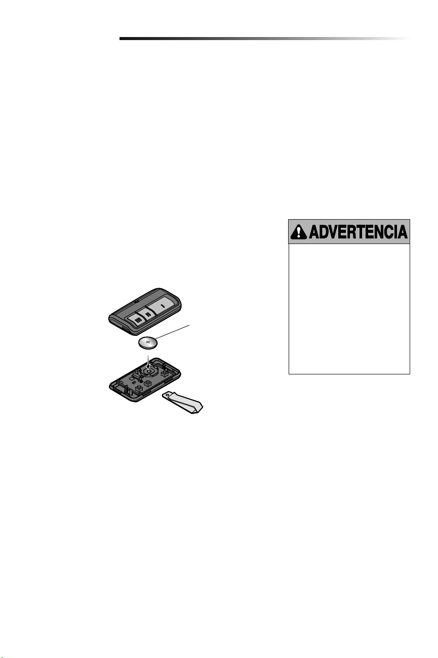
29
Mantenimiento
CALENDARIO DE MANTENIMIENTO
Una vez al mes
• Opere la puerta manualmente. Si está desequilibrada o se atasca, llame a un técnico
especializado en sistemas de puertas.
• Verifique que la puerta se abra y se cierre completamente. Si es necesario, ajuste los
límites y/o la fuerza (consulte los Pasos 1 y 2 de la sección de Ajustes).
• Repita la prueba de reversa de seguridad. Realice los ajustes que sean necesarios
(consulte el Paso 3 de la sección de Ajustes).
Una vez al año
• Ponga aceite en los rodillos, los cojinetes y las bisagras de la puerta. El abre-puertas
de garaje no necesita lubricación adicional. No lubrique los rieles de la puerta.
Mantenimiento del abre-puertas de garaje
Para evitar la posibilidad de LESIONES
GRAVES o incluso LA MUERTE:
• NUNCA permita que los niños
pequeños estén cerca de
lasbaterías.
• Si alguien se traga una batería,
llame al médico de inmediato.
Para reducir el riesgo de incendio,
explosión o combustión química:
• Reemplace ÚNICAMENTE con
baterías planas 3V CR2032.
• NO recargue, desarme, caliente
por encima de 100° C (212° F) o
incinere.
LA BATERÍA DEL CONTROL REMOTO
La DEL del control remoto dejará de parpadear cuando las baterías tengan poca carga y
haya que cambiarlas. Para cambiar las baterías abra la caja tal como se muestra. Colocar
la batería con el lado positivo hacia arriba. Use exclusivamente minibaterías 3V CR2032.
Elimine las baterías usadas en forma adecuada.
1
2
3
3V CR2032
Abrir el control con el
gancho de visera, primero
en el medio (1) y después
de cada lado (2 y 3).
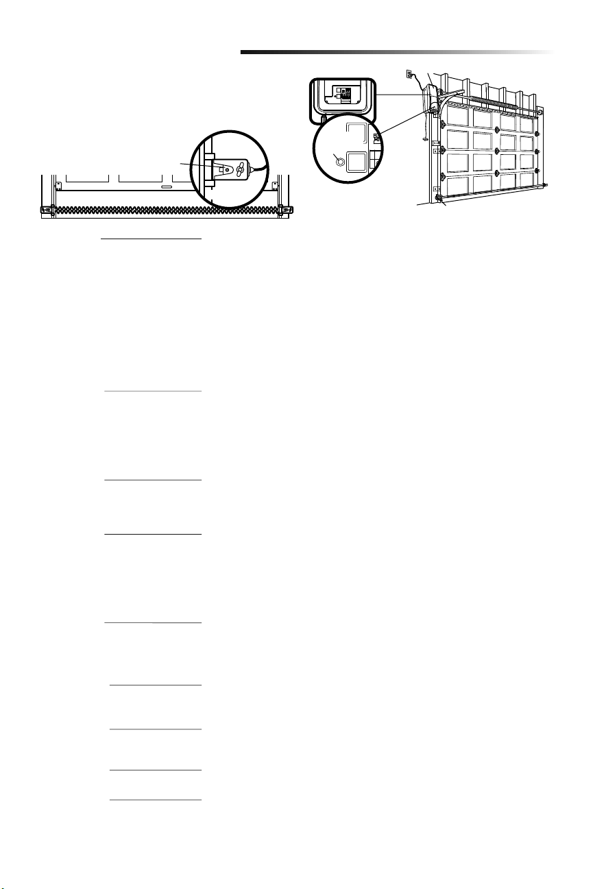
30
Resolución de problemas
Su abre-puertas de garaje viene programado con funciones de
autodiagnóstico. El LED de diagnóstico parpadeará un número de
veces, y luego una pausa, lo que significa que ha encontrado un
problema potencial. Consulte el siguiente Cuadro de diagnóstico.
Tabla de diagnóstico
SÍNTOMA: Una o ambas luces indicadoras de los sensores de seguridad de reversa no
se iluminan continuamente.
• Verifique que no haya ningún corto en los cables de los sensores (una grapa en el
cable), que la polaridad del cableado sea correcta (los cables negros y blancos están
invertidos) y que no haya cables rotos o desconectados. Reemplace o ajuste los
cables, según sea necesario.
• Desconectar todos los cables del abre-puertas de garaje.
• Quite los sensores de los soportes y acorte los cables de los sensores de 30 a 60 cm
(1 a 2 pies) de la parte posterior de cada sensor.
• Conecte nuevamente el emisor al motor utilizando los cables acortados. Si la luz
indicadora del emisor se ilumina continuamente, conecte el receptor.
• Alinee los sensores. Si las luces indicadoras se iluminan, reemplace los cables de
los sensores. Si las luces indicadoras de los sensores no se iluminan, reemplace los
sensores de seguridad de reversa.
SÍNTOMA: El abridor no funciona con el control de la puerta.
• Inspeccione los cables y el control para detectar si hay un cortocircuito (por ejemplo,
en una grapa de fijación), y repare lo que sea necesario.
• Desconecte los cables del control y haga contacto entre ellos. Si se activa el abre-
puertas de garaje, cambiar la consola de control.
• Si el abre-puertas de garaje no funciona, desconectar los conductores de control.
Haga un puente momentáneo entre los terminales rojo y blanco. Si se activa el abre-
puerta, cambiar los conductores de control.
SÍNTOMA: La luz indicadora del emisor se ilumina continuamente, pero la luz
indicadora del receptor es débil o parpadea.
• Realinee el sensor receptor, limpie el cristal y sujete los soportes.
• Verifique que la guía de la puerta esté sujetada firmemente a la pared y que no se
mueva.
SÍNTOMA: La puerta recorrido 5 cm a 7.6 cm (2 a 3 pulg.) y parar.
• Reprogramar los límites de recorrido. Vea la sección de Ajuste.
• Si el motor continúa a recorrido de 5 cm a 7.6 cm (2 a 3 pulg.), verifique que el
conexión del módulo de recorrido o reemplace el módulo de recorrido.
SÍNTOMA: No movimiento, el motor corre 2 a 3 segundos.
• Volver a conectar el desenganche de emergencia.
• Reemplace el motor.
SÍNTOMA: La puerta se detiene e invierte la dirección durante el cierre.
• Verifique si hay posibles obstrucciones a la puerta y quítelas.
• Verifique que el monitor de tensión del cable esté conectado correctamente al
operador.
• Reemplace el monitor de tensión del cable.
SÍNTOMA: La puerta se detiene durante la apertura.
• Debe reprogramar los límites de desplazamiento y las fuerzas. Consulte la sección
Ajuste.
SÍNTOMA: La puerta se detiene e invierte la dirección durante el cierre.
• Debe reprogramar los límites de desplazamiento y las fuerzas. Consulte la sección
Ajuste.
SÍNTOMA: La puerta se detiene e invierte la dirección durante el cierre.
• El abre-puertas de garaje tratará de compensar tres veces antes de generar 10
parpadeos.
SÍNTOMA: La puerta se detiene durante la apertura.
• El abre-puertas de garaje tratará de compensar tres veces antes de generar 11
parpadeos.
Abre-puertas de garaje
Sensor de Reversa de Seguridad
DEL de
diagnóstico
Installed
Safety Reversing
Sensor
Sensor de reversa de
seguridad instalado
1 PARPADEO
Cable de los sensores de seguridad de
reversa abierto (roto o desconectado)
2 PARPADEOS
Cable de sensores de seguridad de
reversa en corto o cables blanco y negro
invertidos
3 PARPADEOS
Cortocircuito en el control o en uno de
sus cables
4 PARPADEOS
Sensores de seguridad de reversa
un poco desalineados (DEL débil o
parpadeante)
5 PARPADEOS
El RPM de motor no es reconocer.
9 PARPADEOS
Inversión del monitor de tensión
del cable
10 PARPADEOS
Debe reprogramar los límites de
desplazamiento y las fuerzas
11 PARPADEOS
Debe reprogramar los límites de
desplazamiento y las fuerzas
12 PARPADEOS
Trata de compensar
13 PARPADEOS
Trata de compensar
O

31
Resolución de problemas
La puerta del garaje no funcionará desde la aplicación de control myQ ni desde el sitio de Internet.
• Al usar la fuente de alimentación de alternativa Modelo 580LM o en modo de batería de reserva, el LiftMaster
®
Internet Gateway
no activará la puerta con la aplicación de control myQ. Si desea usar el LiftMaster
®
Internet Gateway con el abre-puertas de garaje
solicite a su electricista que instale un tomacorriente cerca del abre-puertas de garaje.
El abre-puertas de garaje no funciona con el control de la puerta ni con el control remoto:
• ¿Está el abre-puertas de garaje conectado a la energía eléctrica? Enchufe una lámpara a la toma de corriente. Si no se enciende,
revise la caja de fusibles o el interruptor automático. (Algunas tomas de corriente se controlan con un interruptor de pared.)
• ¿Ha desactivado todos los seguros de la puerta? Revise las advertencias de las instrucciones de instalación que aparecen en la
página 7.
• ¿Hay nieve o hielo acumulado debajo de la puerta? La puerta puede congelarse y quedarse pegada al suelo. Elimine cualquier
restricción.
• El resorte de la puerta del garaje puede estar roto. Haga que lo cambien (para referencia vea página 3).
• Si la DEL de comando amarillo no enciende, invierta los cables conectados a los terminales RED y WHT del panel de control.
Reemplace el cable si es necesario.
Los DEL amarillo y rojo del control de la puerta parpadean rápidamente:
• El panel de control está cargando y podría llevar hasta 5 minutos para volver a funcionar.
El control remoto no activa la puerta del garaje:
• Verifique que el bloqueo no esté activado en el control de la puerta.
• Vuelva a programar el control remoto.
• Si aun así el control remoto no activa la puerta, revise los códigos de diagnóstico para comprobar que el abre-puertas de garaje esté
funcionando correctamente.
El control remoto tiene corto alcance:
• Cambie la ubicación del control remoto en su automóvil.
• Algunas instalaciones pueden tener menor alcance si la puerta es de metal, tiene aislamiento o si el recubrimiento externo del garaje
es de metal.
La puerta no abre completamente:
• Revise el seguro de puerta eléctrico.
• ¿Hay algo que esté obstruyendo la puerta? ¿Está desequilibrada o los resortes están rotos? Elimine la obstrucción o repare la
puerta.
La puerta abre, pero no cierra:
• Revise el monitor de tensión del cable (vea Paso 4 de Instalación).
• Si las luces del abre-puertas de garaje parpadean, revise el sensor de seguridad de reversa (consulte el Paso 9 de la sección de
Instalación).
• Si las luces del abre-puertas de garaje no parpadean y se trata de una instalación nueva (consulte el Paso 2 de la sección de
Ajustes). Para una instalación existente, vea a continuación.
Repita la prueba de reversa de seguridad después de terminar el ajuste.
La puerta retrocede sin ninguna razón en particular y las luces del abre-puertas de garaje no parpadean:
• Revise el monitor de tensión del cable (vea Paso 4 de Instalación).
• ¿Hay algo que esté obstruyendo la puerta? Jale la manija de desenganche de emergencia. Opere la puerta manualmente. Si está
desequilibrada o se atasca, llame a un técnico especializado en sistemas de puertas.
• Limpie el suelo del garaje si tiene hielo o nieve en el punto donde la puerta se cierra.
• Revise el Paso 2 de la sección de Ajustes.
Repita la prueba de seguridad de reversa luego de los ajustes.
Resolución de problemas

32
Resolución de problemas
Resolución de problemas (Continuación)
La puerta no cierra y las luces parpadean:
El sensor de reversa de seguridad debe estar bien conectado y alineado antes de que el abre-puertas de garaje se mueva hacia abajo.
• Verifique que los sensores de seguridad estén debidamente instalados, alineados y libres de obstrucciones.
El abre-puertas de garaje mueve la puerta con dificultad:
• La puerta puede estar desequilibrada o los resortes pueden estar rotos. Ciérrela y use la manija de desenganche de emergencia para
desconectar la puerta. Abra y cierre la puerta manualmente. Si está bien equilibrada, se sostendrá en cualquier punto del recorrido
con sólo el soporte de sus resortes. Si esto no ocurre, desconecte el abre-puertas de garaje y llame a un técnico especializado en
sistemas de puertas.
El motor hace un ruido brevemente y luego no funciona:
• Los resortes de la puerta del garaje pueden estar rotos. Consulte los párrafos anteriores.
• Si el problema se presenta la primera vez que acciona el abre-puertas de garaje, es posible que la puerta esté con seguro. Desactive
el seguro de puerta eléctrico.
El abre-puertas de garaje no funciona por ausencia de alimentación eléctrica:
• Abra el seguro de puerta eléctrico manualmente.
• Use la manija de desenganche de emergencia para desconectar la puerta. La puerta se puede abrir y cerrar manualmente. Cuando
se restaure la alimentación eléctrica, jale el desenganche manual por segunda vez.
• Con reserva de batería, el abre-puertas de garaje debería funcionar hasta 20 veces sin alimentación convencional.
La puerta pierde los límites:
• El collar no está sujetado firmemente. Apriete el collar (consulte los Pasos 1 y 2 de la sección de Ensamblado) y vuelva a programar
los límites (consulte el Paso 1 de la sección de Ajustes).
El abre-puertas de garaje se mueve cuando la puerta está en movimiento:
• Es normal que haya pequeños movimientos en este producto. Si el movimiento es excesivo, el collar se desgastará
prematuramente.
• Verifique que la barra de torsión no se mueva hacia la izquierda ni hacia la derecha excesivamente.
• Verifique que la barra de torsión no se mueva visiblemente hacia arriba o hacia abajo cuando rota.
• Verifique que el abre-puertas de garaje esté montado a un ángulo correcto con respecto al eje secundario. De lo contrario, mueva la
posición del soporte de montaje.
El seguro eléctrico hace ruido cuando funciona:
• Llame al distribuidor de LiftMaster
®
para que reemplace el seguro eléctrico.
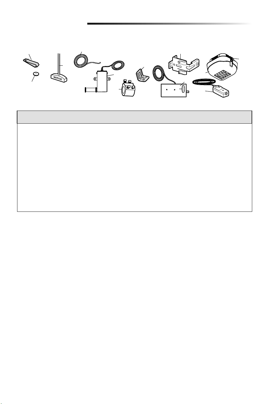
33
Piezas de repuesto
Piezas para la instalación
9
8
10
3
4
5
7
11
12
6
2
1
NÚM. NÚM.
DE CLAVE DE PIEZA DESCRIPCIÓN
1 29B137 Broche de visera para control remoto
2 10A20 Batería de Litio de 3V CR2032
3 41A4582 Ensamble de la manija y la cuerda de
desenganche de emergencia
4 41B4494-1 Cable del timbre de 2 conductores:
blanco y blanco/rojo
5 041A6104 Monitor de tensión del cable
6 041D8615 Collar con tornillos de fijación
7 41C0902 Mensula de montaje
8 41A5266-1 Mensula de sensores de reversa
de seguridad (2)
9 41A6102 Seguro de puerta eléctrico
10 41D96-1 Mica parala luz
NÚM. NÚM.
DE CLAVE DE PIEZA DESCRIPCIÓN
11 41A5034 Juego de sensores de reversa de
seguridad (receptor y emisor) con
cable de 2 conductores
12 380LM Luz remota
(Luz de abre-puertas de garaje)
NO SE MUESTRA
101D173 Barra pulsadora para el control
de la puerta
41A6288 Caja de piezas para la luz de trabajo
41A6298 Caja de piezas para la instalación
(incluye las piezas enumeradas
en la página 5)
114-5281 Manual del propietario
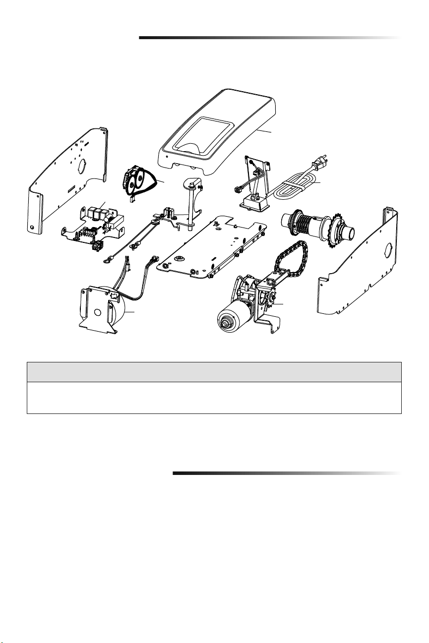
34
Piezas de repuesto
Piezas del abre-puertas de garaje
NÚM. NÚM.
DE CLAVE DE PIEZA DESCRIPCIÓN
1 041DJ002 Tablero lógico completo con placa
2 41A6408 Módulo de viaje
3 41C168 Transformador
NÚM. NÚM.
DE CLAVE DE PIEZA DESCRIPCIÓN
4 41A6095 Motor con soporte
5 41B122 Cable de corriente
6 041A6348-1 Cubierta
Para efectuar pedidos, diríjase a:
LiftMaster
6050 S. Country Club Rd.
Tucson, AZ 85706
Para información sobre instalación y servicio llame:
1-800-528-9131
O visitar a:
LiftMaster.com
Antes que llaman, por favor tener el número de modelo para su abre-puertas de garaje. Cuando necesitar información
de problemas, es recomendado y tiene acceso al su abre-puertas de garaje con llamado. Cuando orden partes de
repuesto, debe proporcionar los siguientes datos: número de parte, nombre de parte y numero de modelo.
Información de contacto
3
2
5
4
1
6
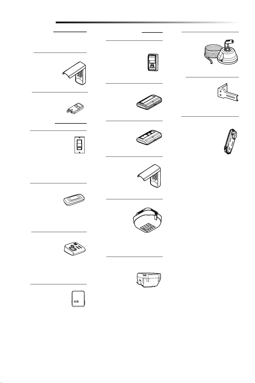
35
Extensiones de soporte:
(Opcionales) Para la
instalación del sensor de
reversa de seguridad en la
pared o en el suelo.
Control de puerta inalámbrico
Security+ 2.0
®
:
Pulsador, luz y botón auxiliar.
Incluye batería.
Juego de montaje alternativo:
Este conjunto pemite que la
modelo 8500 sea montada
de bajo de la barra de torsión
en el cas que la barra de
torsión no es redonda o que
el ara de montaje normal es
obstructivo.
Puerta de garaje y
monitoreo de la puerta:
Monitorea el estado de
apertura/cierre de hasta 4
abre-puertas de garaje o
accionamientos de portones
myQ y los cierra desde cualquier lugar de
su hogar.
Luz remota:
Permite al usuario
encender una luz
de trabajo desde su
automóvil con el control
remoto del abre-puertas
de garaje o desde
cualquier lugar de su casa con un control
remoto LiftMaster Security+
®
adicional.
Comando remoto de
iluminación:
Para controlar
automáticamente las
luces con el abre-puertas de garaje,
un control remoto Security+ 2.0
®
o un
Internet Gateway LiftMaster
®
. Simplemente
reemplaza a la llave de luz.
Internet Gateway LiftMaster
®
:
Accesorio para conexión
a Internet que se conecta
a la computadora para
monitorear y control
abre-puertas de garaje y accesorios de
iluminación con tecnología myQ.
Llave digital inalámbrica MAX:
Utilizado del lado de afuera
para facilitar el ingreso al
garaje con un código de
cuatro dígitos.
Accesorios
890MAX
828LM
41A5281
877MAX
Minicontrol remoto MAX de 3 botones
829LM
885LM
823LM
380LM
480LM
975LM
Asistente láser para
estacionar:
El láser permite al
usuario estacionar
precisamente su
vehículo en el garaje.
ACCESORIOS MAX
Compatible con abre-puertas de garaje
LiftMaster
®
fabricados desde 1993.
ACCESORIOS myQ
ACCESORIOS ESTÁNDAR
Control remoto de un botón:
Incluye broche para visera
de vehículo.
891LM
Control remoto de 3
botones:
Incluye broche para
visera de vehículo.
893LM
Llave digital inalámbrica:
Utilizado del lado de afuera
para facilitar el ingreso al
garaje con un código de
cuatro dígitos.
877LM
Control remoto de iluminación:
Para controlar automáticamente
las luces con el abre-puertas
de garaje, un control remoto
Security+ 2.0
®
o un Internet
Gateway LiftMaster
®
. Se enchufa en
cualquier tomacorriente.
825LM
Reserva de batería:
Proporciona alimentación
eléctrica de reserva al
abre-puertas de garaje.
475LM

36
Garantía
GARANTÍA LIMITADA DE LIFTMASTER
®
LiftMaster
®
El (“Vendedor”) garantiza al primer comprador minorista de este producto, para la residencia en la que
se instaló originalmente este producto, que está libre de defectos de materiales y mano de obra durante un período
específico según se define abajo (el “Período de garantía”). El período de garantía empieza el día de compra.
PERÍODO DE GARANTÍA
Piezas Motor Accesorios Reserva de la batería
5 años
Garantía durante la vida útil
del producto
1 año 1 año
La operación correcta de este producto depende de que usted cumpla las instrucciones referentes a la instalación,
operación, mantenimiento y prueba. El no seguir estrictamente esas instrucciones, anulará por completo ésta
garantía limitada.
Si, durante el período de garantía limitada, parece que este producto contiene un defecto cubierto por esta garantía
limitada, comuníquese al número gratuito 1-800-528-9131 antes de desmontar el producto. Al llamar a este número,
se le proporcionará instrucciones para desmontar y enviar el producto al centro de reparación. A continuación, envíe
el producto o componente, por correo asegurado y con el porte pagado, según las indicaciones al centro de servicio
para que se realicen las reparaciones cubiertas por la garantía. Por favor, incluya una descripción breve del problema
y un recibo fechado como prueba de compra, con cualquier producto devuelto por concepto de reparación cubierta
por la garantía. Los productos devueltos al Vendedor para la reparación cubierta por la garantía, los cuales una vez
recibidos por el Vendedor, se confirme que sean defectuosos y que estén cubiertos por ésta garantía limitada, serán
reparados o reemplazados (a opción únicadel Vendedor) sin costo para usted y serán devueltos con el porte pagado.
Los componentes defectuosos serán reparados o reemplazados a opción única del Vendedor con componentes
nuevos o reconstruidos de fábrica. [Usted es responsable de los costos incurridos en el retiro y/o en la reinstalación
del producto o cualquier componente].
TODAS LAS GARANTÍAS IMPLÍCITAS PARA EL PRODUCTO, INCLUYENDO, ENTRE OTRAS, CUALQUIER GARANTÍA
IMPLÍCITA DE COMERCIALIZACIÓN O DE ADECUACIÓN PARA UN PROPÓSITO PARTICULAR, ESTÁN LIMITADAS
EN DURACIÓN AL PERÍODO DE LA GARANTÍA LIMITADA APLICABLE ESTABLECIDA ANTERIORMENTE PARA LOS
COMPONENTES RELACIONADOS Y, NINGUNA GARANTÍA IMPLÍCITA SURGIRÁ O SE APLICARÁ DESPUÉS DE
DICHO PERÍODO. Algunos estados y provincias no permiten limitaciones sobre la duración de las garantías
implícitas, de tal modo que la limitación mencionada anteriormente podría no corresponder a su caso.
ESTA GARANTÍA LIMITADA NO CUBRE DAÑO ALGUNO QUE SURJA COMO CONSECUENCIA NO RELACIONADA
CON DEFECTO ALGUNO DEL PRODUCTO, NI TAMPOCO CUBRE EL DAÑO CAUSADO POR LA INCORRECTA
INSTALACIÓN, OPERACIÓN O CUIDADO (INCLUYENDO, ENTRE OTROS, EL ABUSO, EL USO INDEBIDO, LA FALTA
DE PROPORCIONAR EL MANTENIMIENTO RAZONABLE Y NECESARIO, REPARACIONES SIN AUTORIZACIÓN O
CUALQUIER ALTERACIÓN A ESTE PRODUCTO), NI LOS CARGOS DE MANO DE OBRA POR LA REINSTALACIÓN
DE UNA UNIDAD REPARADA O REEMPLAZADA, EL REEMPLAZO DE ELEMENTOS CONSUMIBLES (P. EJ.,
BOMBILLAS Y BATERÍAS DE TRANSMISORES DEL CONTROL REMOTO) O UNIDADES INSTALADAS PARA USO NO
RESIDENCIAL. ESTA GARANTÍA LIMITADA NO CUBRE PROBLEMAS CON, O RELACIONADOS A, LA PUERTA DEL
GARAJE O HERRAJES DE LA PUERTA DEL GARAJE, QUE INCLUYEN, ENTRE OTROS, LOS RESORTES, RODILLOS,
ALINEAMIENTOS O BISAGRAS DE LA PUERTA. ESTA GARANTÍA LIMITADA TAMPOCO CUBRE PROBLEMAS
CAUSADOS POR INTERFERENCIA. BAJO NINGUNA CIRCUNSTANCIA EL VENDEDOR SERÁ RESPONSABLE
DE DAÑOS CONSECUENTES, INCIDENTALES O ESPECIALES QUE SURJAN EN RELACIÓN CON EL USO O LA
INCAPACIDAD PARA USAR ESTE PRODUCTO. LA RESPONSABILIDAD DEL VENDEDOR POR VIOLACION DE LA
GARANTIA, POR VIOLACION DEL CONTRATO, NEGLIGENCIA O RESPONSABILIDAD ESTRICTA, EN NINGUN
CASO DEBERA EXCEDER AL COSTO DEL PRODUCTO CUBIERTO POR LA PRESENTE. NINGUNA PERSONA ESTA
AUTORIZADA A ASUMIR EN NUESTRO NOMBRE NINGUNA OTRA RESPONSABILIDAD CON LA VENTA DE ESTE
PRODUCTO.
Algunos estados no permiten la exclusión o limitación de daños emergentes, incidentales o especiales, de manera
que la anterior limitación o exclusión podría no aplicarse a su caso. Esta garantía limitada le proporciona derechos
legales específicos y usted también puede tener otros derechos que varían según el estado y la provincia.
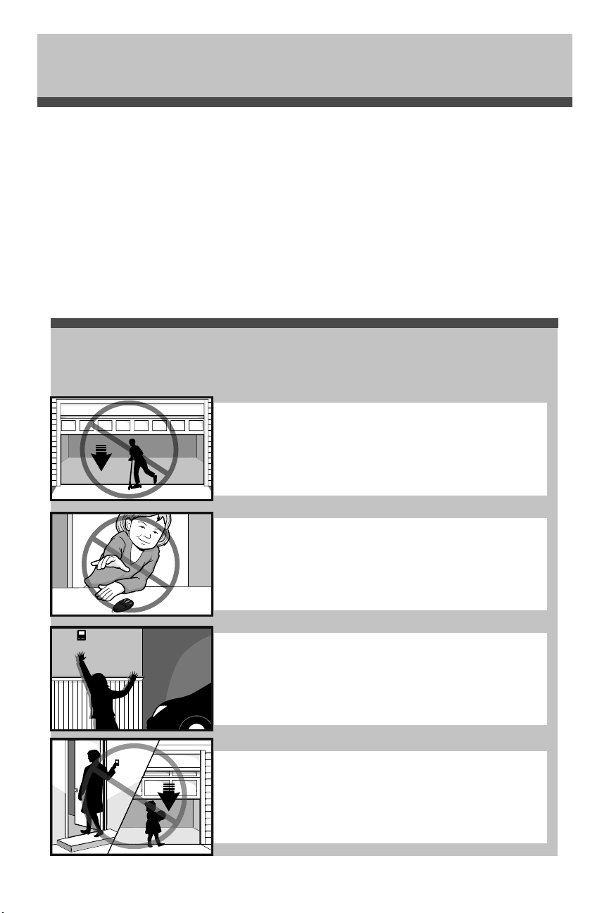
37
Guía de seguridad y mantenimiento del
abre-puertas de garaje automático
Los abre-puertas de garaje no son juguetes
Hable con sus hijos sobre la seguridad de la puerta de garaje y del abre-puertas. Explique el peligro de
quedar atrapado bajo la puerta.
Seguridad del abre-puertas de garaje – Una decisión automática
Manténgase alejado de una puerta en movimiento.
Mantenga los transmisores y los controles remotos fuera
del alcance de los niños. No permita que los niños usen o jueguen
con los transmisores u otros dispositivos de control remoto.
El botón de montaje en la pared debe estar fuera del alcance de
los niños, por lo menos a 1.5 m (5 pies) de la superficie del suelo
y alejado de todas las partes móviles. Monte y use el botón donde
pueda ver claramente la puerta de garaje al cerrarse.
Mantenga su vista en la puerta hasta que se cierre completamente
cuando use el transmisor o botón de montaje en la pared.
Una puerta de garaje es el objeto móvil más grande de la casa. Una puerta y un abre-puertas de garaje mal
ajustados pueden ejercer una fuerza mortal cuando la puerta se cierra, que puede ocasionar el atrapamiento
de niños o adultos y la posterior lesión o muerte.
Es necesario realizar una adecuada instalación, operación, mantenimiento y prueba de la puerta de garaje y del
abre-puertas automático para brindar un sistema seguro y sin problemas.
Una operación descuidada o permitir que los niños usen o jueguen con los controles del abre-puertas de
garaje también ocasionan situaciones peligrosas que pueden provocar resultados trágicos. Algunas sencillas
precauciones pueden proteger a su familia y amigos de daños potenciales.
En este guía encontrará consejos de seguridad y mantenimiento, revíselos detenidamente y conserve el folleto
para referencia futura. Revise la operación de su puerta de garaje y abre-puertas para asegurarse de que
funcionan de manera segura y sin problemas.
Asegúrese de leer toda la Información de seguridad importante en el manual de su abre-puertas de garaje dado
que proporciona más detalles y consideraciones de seguridad que este guía.
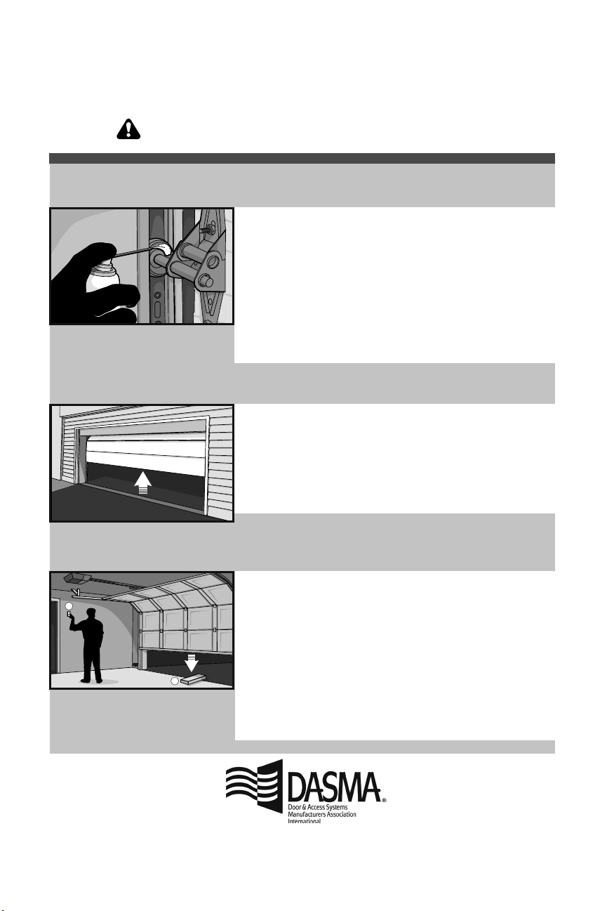
El mantenimiento de rutina puede evitar tragedias
1
2
• Empezando con la puerta en posición cerrada, use la desconexión
manual en el abre-puertas para desconectar la puerta.
• Busque signos de daño o desgaste en bisagras, rodillos, resortes y
paneles de puertas.
• Estas partes pueden requerir una lubricación periódica. Consulte el
manual del propietario para conocer las sugerencias en cuanto al
mantenimiento.
• Si observa signos de daños, llame a un técnico profesional en
sistemas de puertas para obtener asistencia.
• Verifique que la altura del sensor fotoeléctrico no supere las 15 cm
(6 pulg.) desde el piso del garaje.
• Abra y cierre la puerta manualmente usando las manijas o los
puntos de agarre adecuados.
• La puerta debe moverse libremente y sin dificultad.
• La puerta debe equilibrarse y mantenerse parcialmente abierta
de .9 a 1.2 m (3 a 4 pies) por encima del piso.
• Si observa algún signo de operación inadecuada, llame a un
técnico profesional en sistemas de puertas para obtener asistencia.
• Vuelva a conectar el abre-puertas a la puerta usando la
desconexión manual y abra la puerta.
• Coloque una tabla plana de 2 x 4 en el recorrido de la puerta (1) e
intente cerrarla (2). La puerta deberá detenerse cuando entre en
contacto con la tabla de 2 x 4 y luego invertir la dirección.
• Bloquee el sensor fotoeléctrico pasando un objeto enfrente del
sensor e intente cerrar la puerta. La puerta no deberá cerrarse
a menos que el botón de montaje en la pared se mantenga
presionado durante la operación.
• Si el abre-puertas no funciona tal como se describe, llame a
un técnico profesional en sistemas de puertas para obtener
asistencia.
La inspección y prueba mensual de su puerta de garaje y sistema de abre-puertas debe formar parte de su
rutina regular. Consulte el manual del propietario tanto para la puerta como para el abre-puertas. Si no tiene los
manuales del propietario, comuníquese con el fabricante y solicite una copia para su modelo específico. Busque el
número de modelo del abre-puertas en la parte posterior de la unidad de potencia.
Pruebe las funciones de seguridad del
abre-puertas:
Verifique que la puerta funcione
correctamente:
Revise visualmente la puerta y la
instalación:
ADVERTENCIA – Los resortes están en alta tensión.
Solamente las personas calificadas pueden ajustarlos.
© 2018, LiftMaster
All Rights Reserved
114-5281 Todos los Derechos Reservados