
COMMERCIAL DC
VEHICULAR SWING GATE OPERATOR
INSTALLATION MANUAL
LiftMaster
300 Windsor Drive
Oak Brook, IL 60523
• THIS PRODUCT MUST BE INSTALLED AND
SERVICED IN ACCORDANCE WITH THIS
MANUAL BY A TRAINED GATE SYSTEMS
TECHNICIAN ONLY.
• This model is for use on vehicular passage
gates ONLY and not intended for use on
pedestrian passage gates.
• This model is intended for use in Class I, II,
III and IV vehicular swing gate applications.
• Visit LiftMaster.com to locate a professional
installing dealer in your area.
• This gate operator is compatible with myQ
®
and Security+ 2.0
®
accessories.
Access installation and technical support
guides or register this product
Send it in by texting
the photo to 71403.
Take a photo of the
camera icon including
the points (
).
1.
2.
HDSW24ULTECH
Model HDSW24UL

2
SAFETY 2
Safety Symbol and Signal Word Review ................................................2
Usage Class ...........................................................................................3
UL325 Entrapment Protection Requirements ........................................3
Safety Installation Information ...............................................................4
Role of Dealers, Installers, and Trained Gate System Technicians ........5
Role of End Users/Home Owners ..........................................................5
Gate Construction Information ...............................................................6
INTRODUCTION 7
Carton Inventory ....................................................................................7
Operator Specifications ..........................................................................8
Site Preparation .....................................................................................9
Check Your Gate ....................................................................................9
INSTALLATION 10
Types of Installations ...........................................................................10
Step 1 Determine Location for Concrete Pad and Operator .................11
Step 2 Concrete Pad and Operator Attachment ...................................13
Step 3 Position the Gate Bracket .........................................................14
Step 4 Adjust the Operator Arm Length ...............................................14
Step 5 Secure the Operator Arm ..........................................................15
Step 6 Install Entrapment Protection ...................................................16
Step 7 Earth Ground Rod .....................................................................18
Step 8 Power Wiring ............................................................................18
Step 9 Connect Batteries .....................................................................20
Step 10 Dual Gate Setup ......................................................................22
Step 11 Install the Cover .....................................................................24
ADJUSTMENT 25
Limit, Speed, and Force Adjustment ....................................................25
Obstruction Test ..................................................................................27
PROGRAMMING 28
Remote Controls (not provided) ..........................................................28
LiftMaster Internet Gateway (not provided) .........................................29
CAPXL Connected Access Portal .........................................................29
Erase All Codes ....................................................................................30
Erase Limits .........................................................................................30
Constant Pressure Override (CPO) ......................................................30
Gate Hold Open Feature .......................................................................30
To Remove and Erase Monitored Entrapment Protection Devices .......30
OPERATION 31
Gate Operator Setup Examples ............................................................31
Control Board Overview .......................................................................32
Manual Disconnect ..............................................................................33
Reset Switch ........................................................................................33
Relay Board and Terminal Block Access ..............................................33
Operator Alarm ....................................................................................34
Remote Control ....................................................................................34
ACCESSORY WIRING 35
External Control Devices ......................................................................35
Locks ...................................................................................................36
Miscellaneous Wiring ...........................................................................36
EXPANSION AND RELAY BOARDS 37
Expansion and Relay Boards Overview ................................................37
Auxiliary Relays ...................................................................................38
Wiring Accessories to the Expansion Board ........................................39
MAINTENANCE 40
Important Safety Instructions ..............................................................40
Maintenance Chart ...............................................................................41
Batteries ............................................................................................... 41
TROUBLESHOOTING 42
Diagnostic Codes .................................................................................42
Control Board LEDs .............................................................................43
Troubleshooting Chart .........................................................................44
SOLAR PANELS 47
Step 8 Solar Panel(s) ...........................................................................47
REPAIR PARTS 51
ACCESSORIES 52
WARRANTY 54
APPENDIX 55
SAMS Wiring with Relays Not Energized .............................................55
Dual Gate Settings ...............................................................................56
Limit Setup with a Remote Control ......................................................57
Wiring Diagram ....................................................................................58
Diagnostic Codes Table .......................................................................59
Site Planning Safety Checklist .............................................................61
CONTACT INFORMATION 64
WARNING: This product can expose you to chemicals including lead, which are known to the State of California to cause cancer or birth defects
or other reproductive harm. For more information go to www.P65Warnings.ca.gov.
When you see these Safety Symbols and Signal Words on the following pages, they will alert
you to the possibility of Serious Injury or Death if you do not comply with the warnings that
accompany them. The hazard may come from something mechanical or from electric shock.
Read the warnings carefully.
When you see this Signal Word on the following pages, it will alert you to the possibility of
damage to your gate and/or the gate operator if you do not comply with the cautionary
statements that accompany it. Read them carefully.
IMPORTANT NOTE:
• BEFORE attempting to install, operate or maintain the operator, you must read and fully
understand this manual and follow all safety instructions.
• DO NOT attempt repair or service of your gate operator unless you are a Trained Gate
Systems Technician.
MECHANICAL
ELECTRICAL
TABLE OF CONTENTS
SAFETY
Safety Symbol and Signal Word Review
3
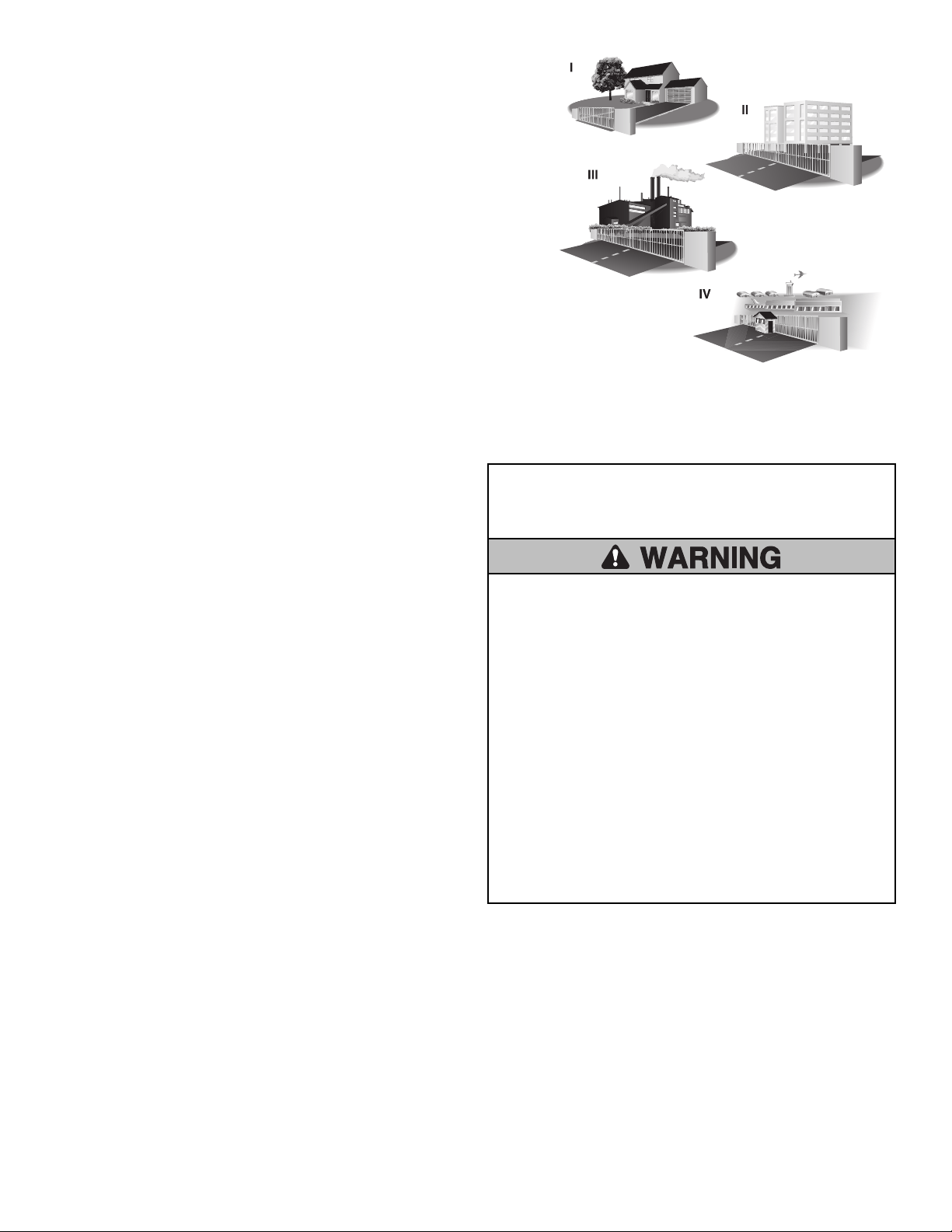
Usage Class
Class I - Residential Vehicular Gate Operator
A vehicular gate operator (or system) intended for use in garages or parking areas
associated with a residence of one-to four single families.
Class II - Commercial/General Access Vehicular Gate
A vehicular gate operator (or system) intended for use in a commercial location or
building such as a multi-family housing unit (five or more single family units), hotel,
garages, retail store, or other buildings accessible by or servicing the general public.
Class III - Industrial/Limited Access Vehicular Gate
A vehicular gate operator (or system) intended for use in an industrial location or
building such as a factory or loading dock area or other locations not accessible by or
intended to service the general public.
Class IV - Restricted Access Vehicular Gate Operator
A vehicular gate operator (or system) intended for use in a guarded industrial location
or building such as an airport security area or other restricted access locations not
servicing the general public, in which unauthorized access is prevented via supervision
by security personnel.
UL325 Entrapment Protection Requirements
Definitions
ENTRAPMENT: The condition when a person is caught or held in a
position that increases the risk of injury.
SWING GATE ENTRAPMENT ZONE: Locations between a moving gate or
moving, exposed operator components and a counter opposing edge or
surface where entrapment is possible up to 1.8 m (6 ft.) above grade.
Such locations occur if during any point in travel:
a. The gap between the bottom of a moving gate and the ground is
greater than 101.6 mm (4") and less than 406 mm (16"); or
b. The distance between the center line of the pivot and the end of the
wall, pillar, or column to which it is mounted when in the open or
closed position exceeds 101.6 mm (4"). Any other gap between a
moving gate and fixed counter opposing edges or surfaces or other
fixed objects is less than 406 mm (16") (examples are walls, curbs,
berms or other immovable objects).
INDEPENDENT MONITORED ENTRAPMENT PROTECTION DEVICE: An
entrapment protection device is independent if it is a different type
(photoelectric sensors, edge device, inherent protection device) from the
other devices in the same entrapment zone.
Use the Site Planning Safety Checklist in the appendix to identify
entrapment zones found in your installation.
Requirements
•
A minimum of two independent monitored entrapment protection
devices are required to be installed at each entrapment zone.
• It is the responsibility of the installer to install external monitored
entrapment protection devices for each entrapment zone.
•
The operator will only operate with a minimum of two independent
monitored entrapment protection devices installed in either the open
or closed direction. If no entrapment zone exists in the other
direction, an external entrapment protection device is NOT required in
that direction.
This operator has an inherent entrapment protection device built-in.
The installer MUST provide one additional entrapment protection
device for each entrapment zone.
Acceptable entrapment protection device types include:
• Inherent (built into the operator)
• LiftMaster monitored external photoelectric sensors, see page 52 for
acceptable sensors.
• LiftMaster monitored external edge sensors, see page 52 for
acceptable sensors.
IMPORTANT SAFETY
INSTRUCTIONS
To reduce the risk of INJURY or DEATH:
• READ AND FOLLOW ALL INSTRUCTIONS.
• NEVER let children operate or play with gate controls. Keep the
remote control away from children.
• ALWAYS keep people and objects away from the gate. NO ONE
SHOULD CROSS THE PATH OF THE MOVING GATE.
• Test the gate operator monthly. The gate MUST reverse on
contact with an object or reverse when an object activates the
noncontact sensors. After adjusting the speed, force, or the limit
of travel, retest the gate operator. Failure to adjust and retest the
gate operator properly can increase the risk of INJURY or DEATH.
• Use the manual release ONLY when the gate is not moving.
• KEEP GATES PROPERLY MAINTAINED. Read this manual. Have a
Trained Gate Systems Technician make repairs to gate hardware.
• The entrance is for vehicles ONLY. Pedestrians MUST use separate
entrance.
• SAVE THESE INSTRUCTIONS.

4
Safety Installation Information
1. Vehicular gate systems provide convenience and security. Gate systems
are comprised of many component parts. The gate operator is only one
component. Each gate system is specifically designed for an individual
application.
2. Gate operating system designers, installers and users must take into
account the possible hazards associated with each individual
application. Improperly designed, installed or maintained systems can
create risks for the user as well as the bystander. Gate systems design
and installation must reduce exposure to potential hazards.
3. A gate operator can create high levels of force in its function as a
component part of a gate system. Therefore, safety features must be
incorporated into every gate system design. Specific safety features
include:
• Edges Sensors (contact)
• Photoelectric Sensors
• Instructional and Precautionary Signage
4. Install the gate operator only when:
a. The operator is appropriate for the construction and the usage
class of the gate.
b. All exposed pinch points are eliminated or guarded.
5. The gate operator is intended for installation only on gates used for
vehicles. Pedestrians must be supplied with a separate access opening.
The pedestrian access opening shall be designed to promote pedestrian
usage. Locate the pedestrian access such that persons will not come in
contact with the vehicular gate during the entire path of travel of the
vehicular gate.
6. The gate must be installed in a location so that enough clearance is
supplied between the gate and adjacent structures when opening and
closing to reduce the risk of entrapment. Swinging gates shall not open
into public access areas.
7. The gate must be properly installed and work freely in both directions
prior to the installation of the gate operator.
8. Permanently mounted access controls intended for users to activate,
must be located at least 6 feet (1.8m) away from any moving part of
the gate and where the user is prevented from reaching over, under,
around or through the gate to operate the controls. Outdoor or easily
accessible controls shall have a security feature to prevent unauthorized
use. Exception: Emergency access controls only accessible by
authorized personnel (e.g. fire, police) may be placed at any location in
the line-of-sight of the gate.
9. For a gate operator utilizing a Stop and/or Reset button, it must be
located in the line-of-sight of the gate. Activation of the reset control
shall not cause the operator to start.
10. A minimum of two (2) WARNING SIGNS shall be installed in the area
of the gate. Each warning sign is to be visible by persons located on
the side of the gate on which the sign is installed.
11. For a gate operator utilizing a non-contact sensor:
a. See Install Entrapment Protection section for placement of non-
contact sensor for each type of application.
b. Care shall be exercised to reduce the risk of nuisance tripping,
such as when a vehicle trips the sensor while the gate is still
moving.
c. One or more non-contact sensors shall be located where the risk of
entrapment or obstruction exists, such as the perimeter reachable
by a moving gate or barrier.
12. For a gate operator utilizing a contact sensor such as an edge sensor:
a. One or more contact sensors shall be located where the risk of
entrapment or obstruction exists.
b. A hard wired contact sensor shall be located and its wiring
arranged so the communication between the sensor and the gate
operator is not subject to mechanical damage.
c. A wireless device such as one that transmits radio frequency (RF)
signals to the gate operator for entrapment protection functions
shall be located where the transmission of the signals are not
obstructed or impeded by building structures, natural landscaping
or similar obstruction. A wireless device shall function under the
intended end-use conditions.
d. One or more contact sensors shall be located on the inside and
outside leading edge of a swing gate. Additionally, if the bottom
edge of a swing gate is greater than 4 inches (10.1 cm) but less
than 16 inches (406 mm) above the ground at any point in its arc
of travel, one or more contact sensors shall be located on the
bottom edge.
SAFETY

5
Role of Dealers, Installers, and
Trained Gate System Technicians
• Ensure entire system being designed manufactured and installed meets
all applicable standards and codes including UL 325 and ASTM F2200.
• Demonstrate the basic functions and safety features of the gate system to
owners/end users/general contractors, including how to turn off power
and how to operate the manual disconnect feature.
• Leave safety instructions, product literature, installation manual and
maintenance manual with end user.
• Explain to the owners the importance of testing by a trained gate system
technician that includes a routine re-testing of the entire system
including the entrapment protection devices, and explain the need for
the owners to insure that this testing is performed monthly.
Role of End Users/Home Owners
• Contact a trained gate systems technician to maintain and repair the gate
system (End users should never attempt to repair the gate system).
• Retain and utilize the installation manual and maintenance and
important safety instructions; see page 40.
• Routinely check all gate operator functions and gate movement.
• Discontinue use if safety systems operate improperly, the gate is
damaged, or the gate is difficult to move. Contact trained gate systems
technician to repair the gate system.
• Prominently display and maintain warning signs on both sides of the
gate.
SAFETY

6
Gate Construction Information
Vehicular gates should be installed in accordance with ASTM F2200: Standard Specification for Automated Vehicular Gate Construction. For a copy,
contact ASTM directly at 610-832-9585 or www.astm.org.
1. General Requirements
1.1 Gates shall be constructed in accordance with the provisions
given for the appropriate gate type listed, refer to ASTM F2200
for additional gate types.
1.2 Gates shall be designed, constructed and installed to not fall
over more than 45 degrees from the vertical plane, when a
gate is detached from the supporting hardware.
1.3 Gates shall have smooth bottom edges, with vertical bottom
edged protrusions not exceeding 0.50inches (12.7 mm) when
other than the exceptions listed in ASTM F2200.
1.4 The minimum height for barbed tape shall not be less than 8
feet (2.44m) above grade and for barbed wire shall not be
less than 6 feet (1.83m) above grade.
1.5 An existing gate latch shall be disabled when a manually
operated gate is retrofitted with a powered gate operator.
1.6 A gate latch shall not be installed on an automatically operated
gate.
1.7 Protrusions shall not be permitted on any gate, refer to ASTM
F2200 for Exceptions.
1.8 Gates shall be designed, constructed and installed such that
their movement shall not be initiated by gravity when an
automatic operator is disconnected, in accordance with the
following.
1.8.1 Vehicular horizontal swing gate shall not result in continuous,
unimpeded movement in either direction along the arc of its
path of travel.
1.9 For pedestrian access in the vicinity of an automated vehicular
gate, a separate pedestrian gate shall be provided. The
pedestrian gate shall be installed in a location such that a
pedestrian shall not come in contact with a moving vehicular
access gate. A pedestrian gate shall not be incorporated into
an automated vehicular gate panel.
2. Specific Applications
2.1 Any non-automated gate that is to be automated shall be
upgraded to conform to the provisions of ASTMF2200.
2.2 This specification shall not apply to gates generally used for
pedestrian access and to vehicular gates not to be automated.
2.3 When the gate operator requires replacement, the existing gate
shall be upgraded to conform to the provisions of
ASTMF2200.
2.4 When the gate of an automated gate system requires
replacement, the new gate shall conform to the provisions of
ASTMF2200.
3. Vehicular Horizontal Swing Gate
3.1 The following provisions shall apply to Class I, Class II and Class III
vehicular horizontal swing gates:
3.1.1 Gates shall be designed, constructed and installed so as not to
create an entrapment zone between the gate and the supporting
structure or other fixed object when the gate moves toward the fully
open and/or close position, subject to the provisions in 3.1.1.1 and
3.1.1.2
3.1.1.1 The width of an object (such as a wall, pillar or column) covered by
a swing gate when in the open position shall not exceed 4inches
(102mm), measured from the center line of the pivot point of the
gate. Exception: For a gate not in compliance with this provision,
the defined area must be provided with entrapment protection per
UL325.
3.1.1.2 Except for the zone specified in Section 3.1.1.1, the distance
between a fixed object such as a wall, pillar or column, and a swing
gate when in the open position shall not be less than 16inches
(406mm). Exception: For a gate not in compliance with this
provision, the defined area must be provided with entrapment
protection per UL325.
3.2 Class IV vehicular horizontal swing gates shall be designed,
constructed and installed in accordance with security related
parameters specific to the application in question.
SAFETY
7
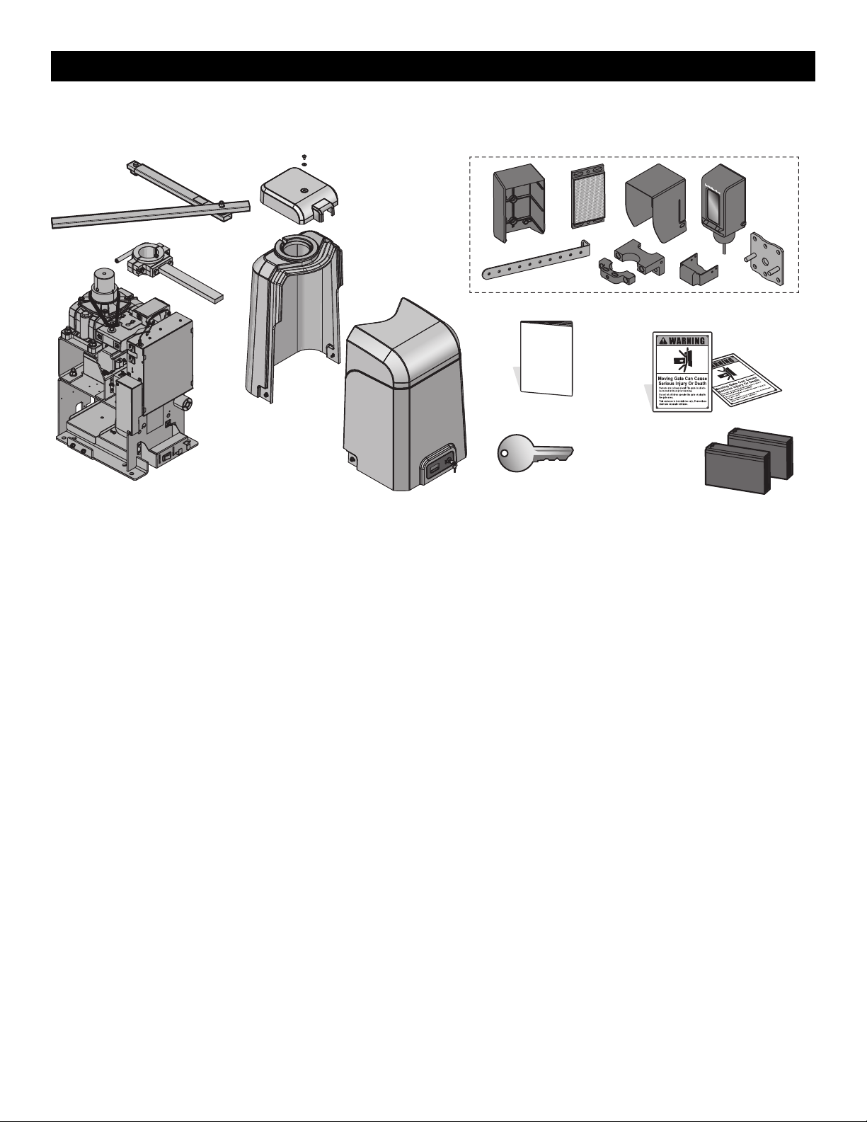
Carton Inventory
NOT SHOWN: Documentation packet and hardware bag
LiftMaster Monitored Retro-Reflective Photoelectric Sensor Model LMRRUL
Key (2)
Battery 12 Vdc 7AH (2)
Cover
Standard Arm Assembly
Operator
MONITORED ENTRAPMENT PROTECTION DEVICE
Warning Signs (2)
Installation Manual
INTRODUCTION
8
Operator Specifications
Usage Classification
Class I, II, III, & IV
Main AC Supply 120 Vac, 4 Amps (10 Amps including Accessory Outlets) OR 240 Vac, 2 Amps
When Optional Transformer Kit Model 3PHCONV is installed in the field, operator is rated
208/240/480/575 VAC, 5.2/4.5/2.3/1.9 A, 60 Hz, 1 PH
System Operating Voltage
24 Vdc Transformer Run / Battery Backup
Accessory Power
24 Vdc, 1A max. for ON + SW (switched)
Solar Power Max
24 Vdc at 60 watts max.
Maximum Gate Weight/Length
14 ft. - 2,800 lbs.
16 ft. - 2,400 lbs.
18 ft. - 2,200 lbs.
20 ft. - 1,800 lbs.
22 ft. - 1,500 lbs.
To optimize performance and extend operator life, the long arm kit model HDLGARM is
recommended when installing with gates 16ft. or longer. See Accessories page 53.
When HDLGARM is used, operator has the following maximum gate weight/length:
14 ft. - 4,500 lbs.
16 ft. - 3,750 lbs.
18 ft. - 3,250 lbs.
20 ft. - 2,750 lbs.
22 ft. - 2,500 lbs.
90 Degree Travel Time 13-36 seconds NOTE: Travel time will vary based on arm configuration and speed controlsettings.
Maximum Travel Range 115 degrees NOTE: Travel range will very based on arm configuration.
Maximum Daily Cycle Rate
Continuous
Maximum Duty Cycle
Continuous
Operating Temperature
Without Heater: -20°C to 60°C (-4°F to 140°F)
With Optional Heater: -40°C to 60°C (-40°F to 140°F)
External Entrapment Protection Device Inputs
(non-contact and/or contact)
Main board - up to 2 close entrapment protection devices and 1 open entrapment protection device.
Expansion board - up to 3 entrapment protection devices configurable to either the close or open
direction and up to 8 edge sensors when using the wireless edge sensor kit model LMWEKITU and
LMWETXU.
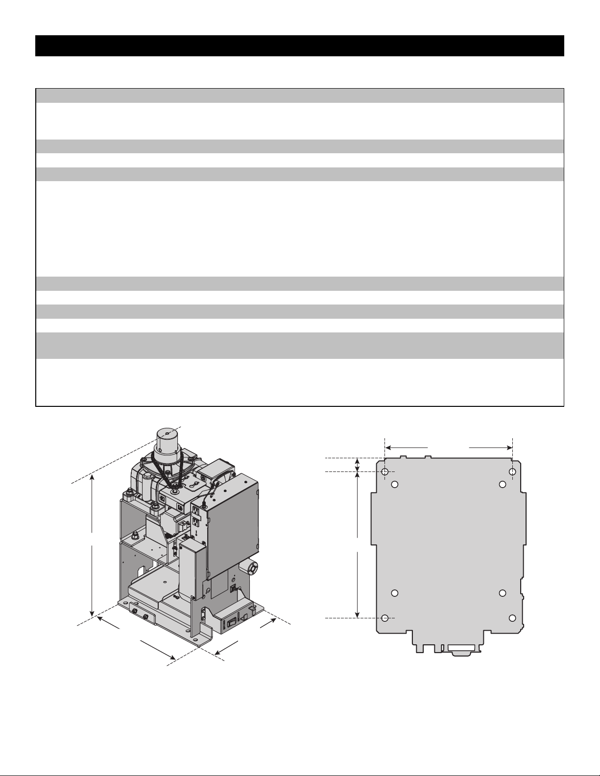
27.85" (70.7 cm)
14.82" (37.6 cm)
16.77" (42.6 cm)
1.31" (3.3 cm)
14" (35.6 cm)
12.2" (31 cm)
INTRODUCTION
9
Site Preparation
Check the national and local building codes BEFORE installation. Refer also to the Site Planning Safety Checklist in the Appendix.
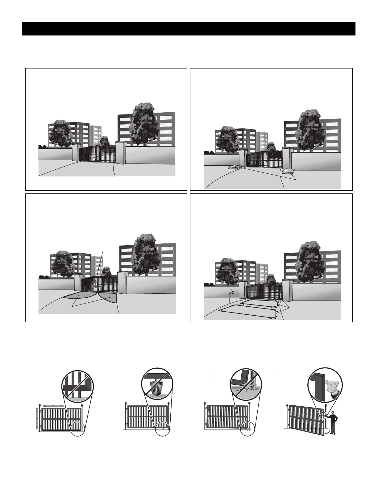
Gate
Gate must be constructed and installed according to ASTM F2200
standards (refer to page 4). Gate must fit specifications of operator (refer
to specifications).
Inside Property
Conduit and Concrete Pad
Trench and install conduit. Before trenching, contact underground utility
locating companies. Conduit must be UL approved for low and high
voltage. Consider the operator placement BEFORE installing the pad or
post.
Concrete Pads
Inside Property
Safety
Entrapment protection devices are required to protect against any
entrapment or safety conditions encountered in your gate application.
Install a warning sign (two provided) on the inside and outside of the
property, where easily visible.
Entrapment Danger
Inside Property
Warning Signs
Additional Accessories
The vehicle loops allow the gate to stay open when vehicles are
obstructing the gate path. Suggested for vehicles 14 feet (4.27 m) or
longer. Vehicle loops are not required but are recommended. Before
installing your Access Control Device(s) be sure to complete a site survey
and determine the best device for your site needs.
Access Control
Device
Outside Property
Vehicle Loops
Check your gate
Gate MUST be level. Gate and gate
post MUST be plumb. Gate MUST
have a smooth bottom edge, no
protrusions should exist.
Remove ANY/ALL wheels from the
bottom of gate.
Gate MUST NOT hit or drag across
ground
Gate MUST swing freely and be
supported entirely by its hinges.
INTRODUCTION
10
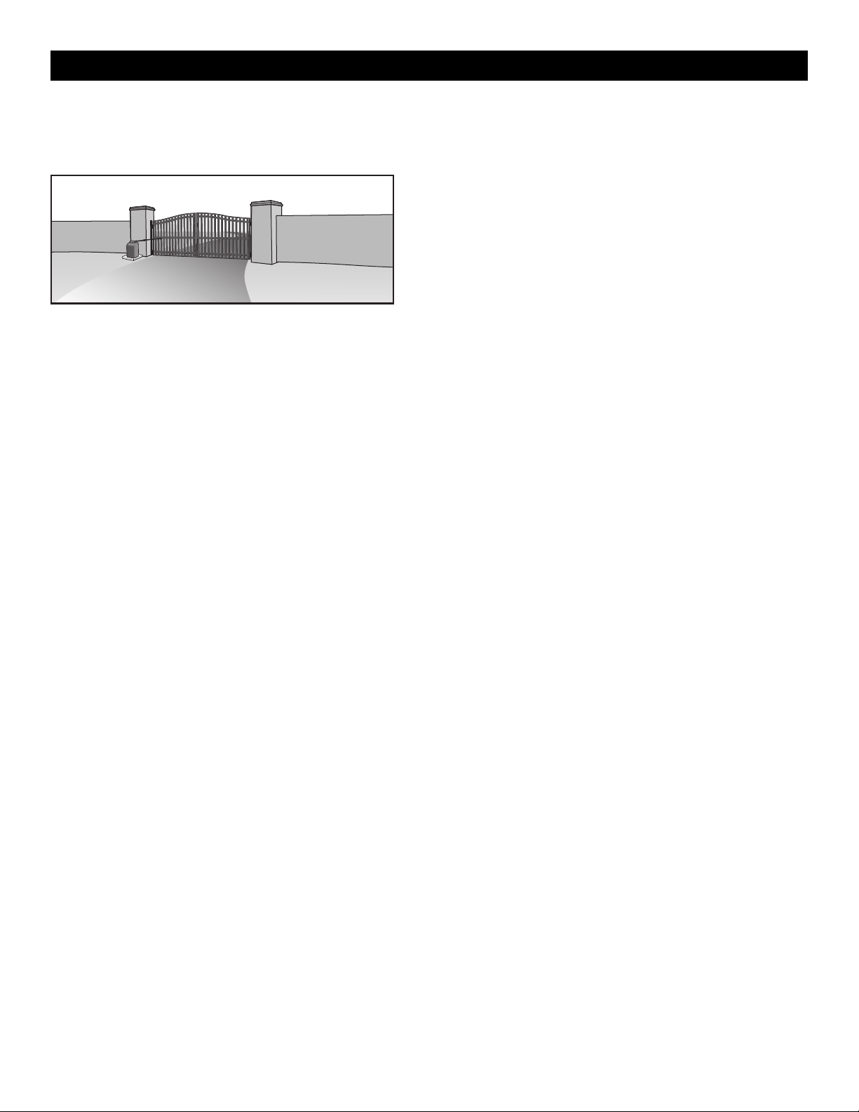
Types of Installations
Standard Installation
The illustration is an example of a standard installation.
Inside Property
INSTALLATION
11
• To AVOID damaging gas, power or other underground utility lines,
contact underground utility locating companies BEFORE digging more
than 18 inches (46 cm) deep.
• ALWAYS wear protective gloves and eye protection when changing
the battery or working around the battery compartment.
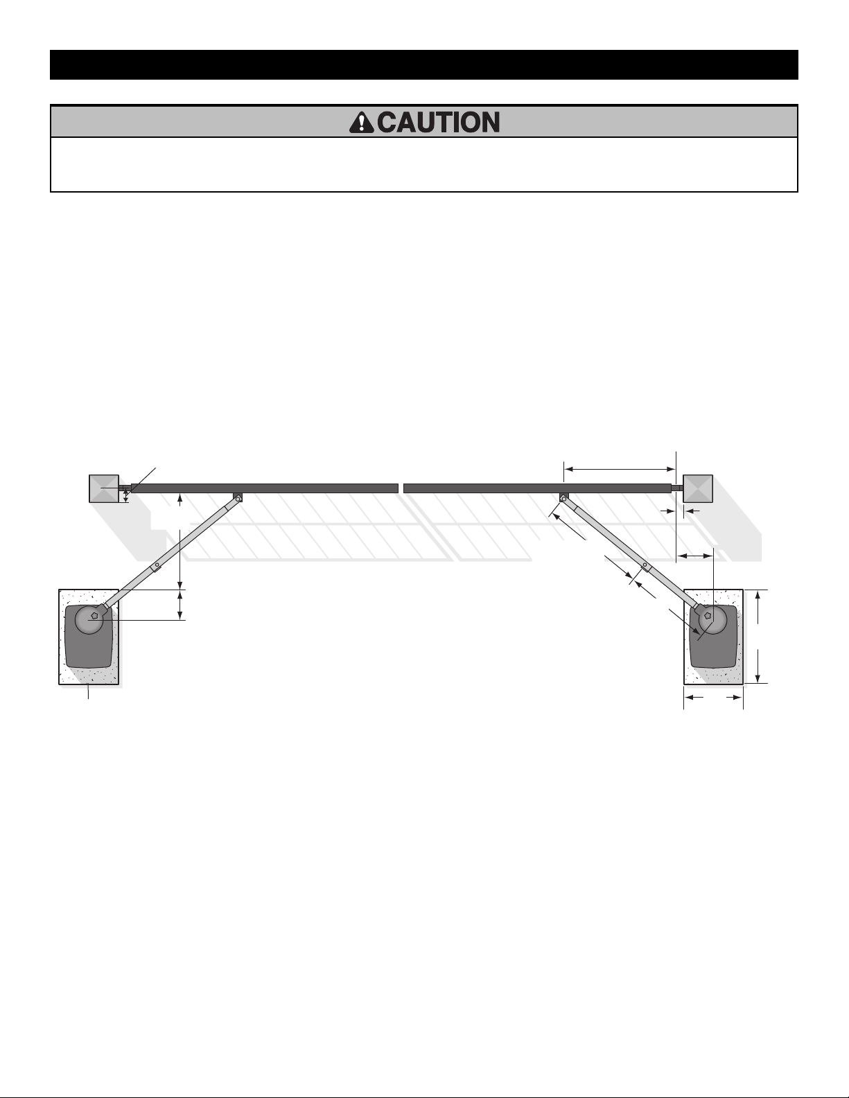
Step 1 Determine Location for Concrete Pad and Operator
DO NOT run the operator until instructed.
To optimize performance and extend operator life, the long arm kit model HDLGARM is recommended when installing with gates 16 ft. or longer.
Follow the installation instructions included with the kit. See Accessories page 53.
The illustration below shows the recommended dimensions for a standard installation using the standard arm provided with the operator. If these
dimensions are not applicable for your installation refer to the charts on the following page for alternate dimensions.
Standard Installation
Refer to the illustration to determine the measurements and location of the concrete pad.
NOTE: There should only be a maximum of 4" (10.2 cm) from the center of the hinge to the edge of the post or column. If the distance is greater than 4"
(10.2 cm) entrapment protection for this area is required.
Outside Property
46" (116.8 cm)
Hinge Center
2" (5.1 cm)
11"
27.9 cm)
Inside Property
Concrete Pad
10" (25.4 cm)
4" (10.2 cm) maximum
25"
(63.5 cm)
Long Arm Section
35.5" (90.2 cm)
Short Arm Section
29.5" (74.9 cm)
28"
(71.1 cm)
24"
(61 cm)
INSTALLATION
12
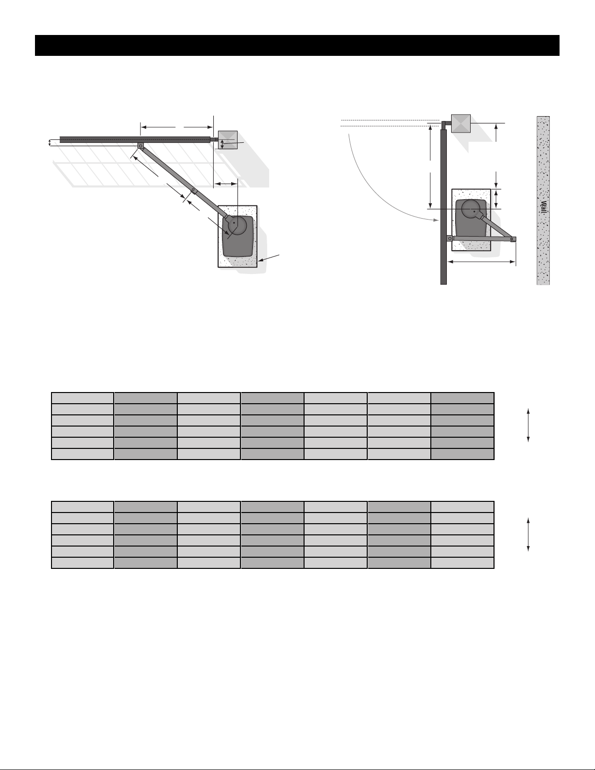
Chart Installation
Refer to the illustration to determine the measurements and location of the concrete pad.
Inside
Outside
Inside
Outside
Wall
A
F
B
C
D
10"
(25.4 cm)
DISTANCE
E
Long Arm Section
Short Arm Section
Concrete Pad
Gate Hinge Center
NOTE: There should only
be a maximum of
4" (10.2 cm) from the
center of the hinge to the
edge of the post or
column. If the distance is
greater than 4" (10.2 cm),
entrapment protection for
this area is required.
D MINUS 10"
(25.4 cm)
Dimension (A) thru (E) are from the center of one pivot point to the center of another pivot point.
Caution: If the gate is longer than 18 feet (5.5 m), follow CHART A: ROW 6.
Suggestion: The dimensions between the gate and the concrete pad is always 10 inches (25.4 cm) less than the dimension D.
Example: D = 42" (106.7 cm), if the dimensions between the gate and the concrete pad is 32" (81.3 cm).
Chart A - Travel Range Up to 90°
A B C D E F DISTANCE
1
47.3" (120 cm) 37.3" (94.6 cm) 30" (76.2 cm) 37" (94 cm) 11" (27.9 cm) 3" (7.6 cm) 45" (114.3 cm)
Heavy Gate/Slow
2
46" (116.8 cm) 35.5" (90.2 cm) 29.5" (74.9 cm) 35" (90.2 cm) 11" (27.9 cm) 3" (7.6 cm) 45" (114.3 cm)
3
46.8" (118.8 cm) 37" (94 cm) 31.5" (80 cm) 40" (101.6 cm) 11" (27.9 cm) 3" (7.6 cm) 41" (104.1 cm)
4
42.5" (108 cm) 33" (116.8 cm) 26.5" (67.3 cm) 28.5" (72.4 cm) 11" (27.9 cm) 3" (7.6 cm) 41" (104.1 cm)
5
47" (119.4 cm) 35" (90.2 cm) 29.5" (74.9 cm) 32" (81.3 cm) 11" (27.9 cm) 3" (7.6 cm) 45" (114.3 cm)
6
46.8" (118.8 cm) 35.5" (90.2 cm) 33.5" (85.1 cm) 42" (106.7 cm) 11" (27.9 cm) 3" (7.6 cm) 37" (94 cm)
Light Gate/Fast
Chart B - Travel Range Greater Than 90°
A B C D E F DISTANCE
1
41" (104.1 cm) 39" (99.1 cm) 27.5" (69.9 cm) 28.5" (72.4 cm) 14" (35.6 cm) 3" (7.6 cm) 41" (104.1 cm)
Heavy Gate/Slow
2
45" (114.3 cm) 37" (94 cm) 30.5" (77.5 cm) 37" (94 cm) 14" (35.6 cm) 3" (7.6 cm) 43" (109.2 cm)
3
44.8" (113.7 cm) 35.8" (90.8 cm) 29.5" (74.9 cm) 32" (81.3 cm) 14" (35.6 cm) 3" (7.6 cm) 44" (111.8 cm)
4
34.5" (87.6 cm) 34.8" (88.3 cm) 29.5" (74.9 cm) 35" (90.2 cm) 14" (35.6 cm) 3" (7.6 cm) 43" (109.2 cm)
5
44" (111.8 cm) 37" (94 cm) 30.5" (77.5 cm) 40" (101.6 cm) 14" (35.6 cm) 3" (7.6 cm) 40" (101.6 cm)
4
44" (111.8 cm) 36.5" (92.7 cm) 32.5" (82.6 cm) 42" (106.7 cm) 14" (35.6 cm) 3" (7.6 cm) 32" (81.3 cm)
Light Gate/Fast
INSTALLATION
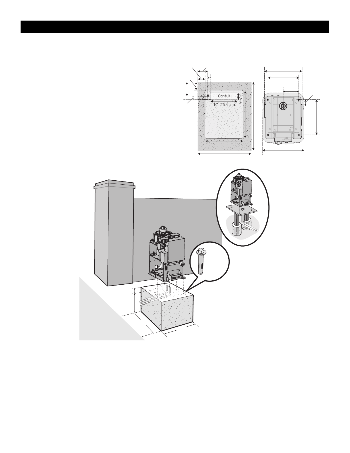
13
Step 2 Concrete Pad and Operator Attachment
CHECK the national and local building codes before installation.
NOTE: When lifting the operator use the handle to avoid damaging the
operator
1. Install the electrical conduit.
2. Pour a concrete pad (reinforced concrete is recommended). The
concrete pad should be 6 inches (15.2 cm) above the ground and
deeper than the frost line. Ensure the pad is tall enough to avoid
possible flooding.
3. Secure the operator to the concrete pad with appropriate fasteners.
NOTE: An alternative to a concrete pad is to post mount the operator, see
Accessories.
Cover Mounting Distance
24" (61 cm)
Pad
15" (38.1 cm)
10" (25.4 cm)
1" (2.5 cm)
5.5"
(14 cm)
4.5"
(11.4 cm)
4"
(10.1 cm)
1.5"
(3.8 cm)
Conduit
3" (7.6 cm)
Mounting FootprintConduit Location
16.4" (41.7 cm)
2.5"
(6.3 cm)
6.1"
(15.5 cm)
28" (71.1 cm)
20" (50.8 cm)
6.5"
(16.5 cm)
14" (35.6 cm)
12.2" (31 cm)
14.82" (37.6 cm)
Post Mount
6 Concrete
Anchors
1/2" x 3 1/2"
24"
(61 cm)
28"
(71.1 cm)
Below the frost line.
Check all national
and local codes.
6" (15.2 cm) Above Ground
INSTALLATION
14
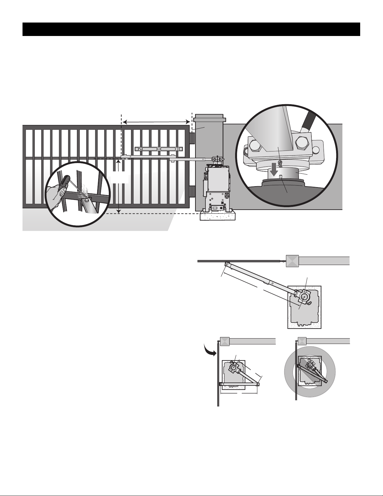
Step 3 Position the Gate Bracket
NOTE: It may be necessary to attach horizontal reinforcement to the gate before attaching the gate bracket.
1. Position the operator arm onto the output shaft so that the pin slides into the slot.
2. Measure 46" (116.8 cm) or Distance A if using the chart installation, along the gate length from the gate hinge center.
3. Measure 27.5" (69.9 cm) up from the concrete pad to the gate hinge position on the gate as shown.
4. Make sure the operator arm is level and tack weld the gate bracket in this position. Use a clamp to temporarily hold the arm in place while determining
the correct measurements.
Output Shaft
Pin
Slot
Gate
Hinge
Center
46" (116.8 cm) or Distance A
Tack weld
27.5"
(69.9 cm)
Step 4 Adjust the Operator Arm
Length
NOTE: The length of the arm can be adjusted if necessary. If adjusting the
length, ensure that both sections of the arm are adjusted proportionally.
Use a clamp to temporarily hold the arm in place while determining the
correct measurements.
1. Close the gate and measure the distance of the operator arm from the
gate bracket to the output shaft center. This distance is E.
2. Open the gate 90° (do not allow arms to scissor when open).
Measure both sections of the arm (D and C). The arm lengths are
correct as long as C+D=E (arm should be perpendicular to the gate
in the open position as shown).
Top view - closed gate
Top view - open gate
Gate
Open
90°
Output Shaft
2
1
Output Shaft
E
C
D
INSTALLATION
15
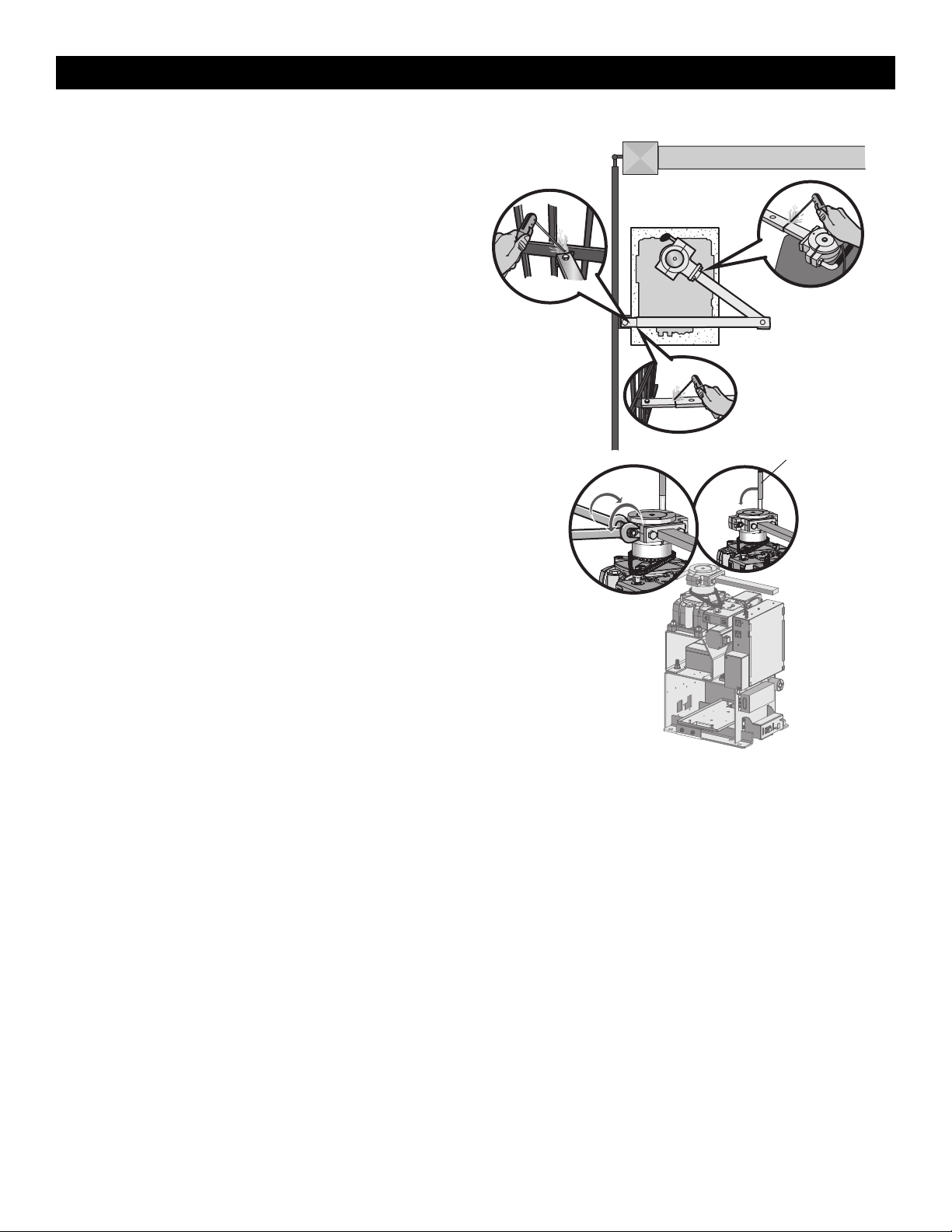
Step 5 Secure the Operator Arm
Once the operator arm measurements are verified:
1. Weld the gate bracket to the gate.
2. Weld the short arm section. Plug/slot weld top and bottom.
3. Weld the long arm section. Plug/slot weld top and bottom.
NOTE: Completely weld around the outer tubing and bracket.
4. Adjust the nuts on the operator arm so the operator arm fits snug on
the output shaft yet still allows enough room to swivel (the handle
must be in a 90° position).
5. Tighten the handle by pushing it down. Test to make sure the
operator arm does not slip on the output shaft.
Manual release handle
INSTALLATION
16
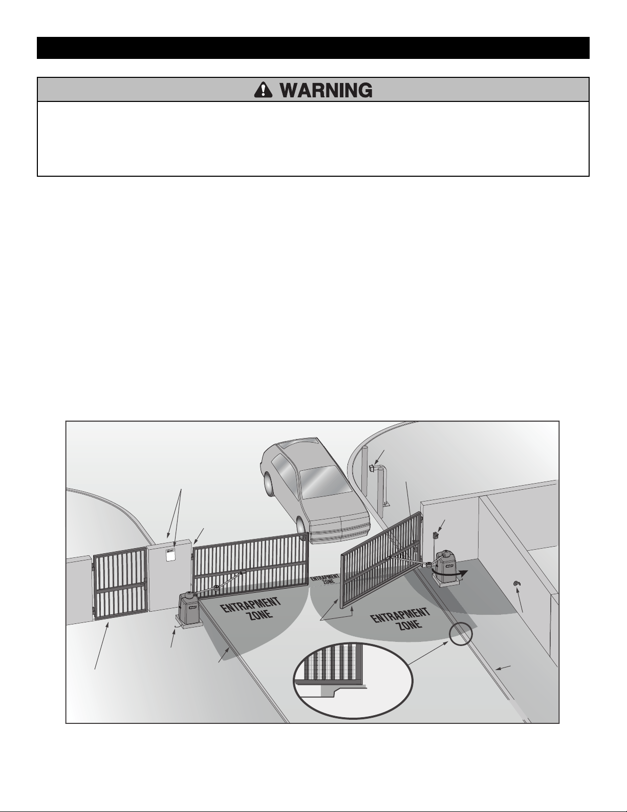
To prevent SERIOUS INJURY or DEATH from a moving gate:
• ALL gate operator systems REQUIRE two independent entrapment
protection systems for each entrapment zone.
• Entrapment protection devices MUST be installed to protect anyone
who may come near a moving gate.
• Entrapment protection devices MUST be located to protect in BOTH
the open and close gate cycles.
• Locate entrapment protection devices to protect between moving gate
and RIGID objects, such as posts, walls, pillars, columns, or operator
itself.
Step 6 Install Entrapment Protection
Install entrapment protection devices according to the UL 325
Entrapment Protection Requirements section, see page 3. Use the Site
Planning Safety Checklist in the appendix, to identify entrapment zones
that will result from the installation.
1. Install entrapment protection devices for ALL entrapment zones. This
operator has an inherent entrapment protection device built-in. The
installer MUST provide one additional entrapment protection device
for each entrapment zone.
2.
The operator will NOT run unless a minimum of one external device
is connected in either the open or closed direction. If no entrapment
zone exists in the other direction, an external entrapment protection
device is NOT required in that direction.
3. Test ALL entrapment protection devices AFTER installing the
operator, refer to the manual provided with your entrapment
protection device.
Illustration is for example only; your site may have additional entrapment
zones which MUST be protected.
Definitions
ENTRAPMENT: The condition when a person is caught or held in a
position that increases the risk of injury.
SWING GATE ENTRAPMENT ZONE: Locations between a moving gate or
moving, exposed operator components and a counter opposing edge or
surface where entrapment is possible up to 1.8 m (6 ft) above grade. Such
locations occur if during any point in travel:
a. The gap between the bottom of a moving gate and the ground is
greater than 101.6 mm (4 in) and less than 406 mm (16 in); or
b. The distance between the center line of the pivot and the end of the
wall, pillar, or column to which it is mounted when in the open or
closed position exceeds 101.6 mm (4 in). Any other gap between a
moving gate and fixed counter opposing edges or surfaces or other
fixed objects is less than 406 mm (16 in) (examples are walls, curbs,
berms or other immovable objects).
See Accessories for approved entrapment protection devices.
Cross Section
Pedestrian gate located near
the swing gate. Make sure a
separate pedestrian entrance
is available and the path is
clearly designated.
Secure Side
Public Side
Edge
sensor
Entrapment
zone
Curb
Curb
Reflector for
photoelectric
sensor
Photoelectric
sensor
Photoelectric sensor
(public side)
Photoelectric sensor
(public side)
Earth ground
Mount access control devices at
least 6' (1.8 m) beyond the gate
Place the warning signs on both
sides of the gate in clear view
E
N
T
RAPME
N
T
Z
O
NE
Take a photograph of the complete
installation site for your records
Illustrations provided by DASMA Gate Systems Safety Guide
INSTALLATION
17
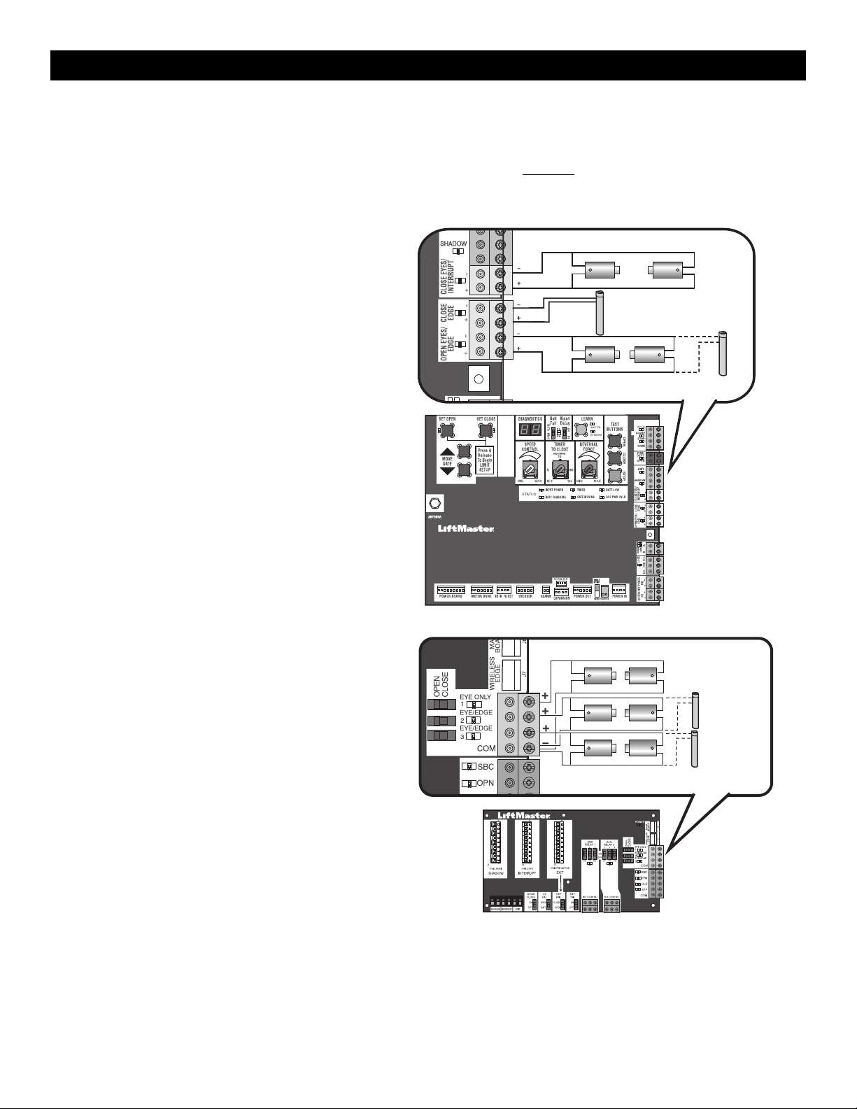
Wire Entrapment Protection Devices
There are three options for wiring external entrapment protection devices depending on the specific device and how the device will function. Refer to the
manual included with your entrapment protection device for more information. These entrapment protection device inputs are for monitored devices, which
include pulsed photoelectric sensors, resistive edge sensors, and pulsed edge sensors. Only one monitored entrapment protection device may be wired
to each input. Additional monitored entrapment protection devices may be wired to the expansion board.
NOTE: Board inputs for entrapment protection devices are yellow.
Control Board
CLOSES EYES/INTERRUPT
(2 Terminals) The CLOSE EYES/INTERRUPT input is for photoelectric
sensor entrapment protection for the close direction. When an
obstruction is sensed during gate closing the gate will open to the full
open position and resets the Timer-to-Close. This input will be
disregarded during gate opening.
CLOSE EDGE
(2 Terminals) The CLOSE EDGE input is for edge sensor entrapment
protection for the close direction. When an obstruction is sensed during
gate closing the gate will reverse to the full open position, disengaging
the Timer-to-Close. This input will be disregarded during gate opening.
OPEN EYES/EDGE
(2 Terminals) The OPEN EYES/EDGE input is for photoelectric sensor or
edge sensor entrapment protection for the open direction. When an
obstruction is sensed during gate opening the gate will reverse for 4
seconds then stop. This input will be disregarded during gate closing.
Close Photoelectric Sensors
Open Photoelectric Sensors OR Open Edge
Close Edge
Expansion Board
EYE ONLY and COM
Open or Close Direction Photoelectric Sensors, the functionality is based
on the switch settings (located next to the terminals)
Switch set to CLOSE: gate reverses fully when an obstruction is sensed
Switch set to OPEN: gate reverses 4 seconds when an obstruction is
sensed
EYE/EDGE and COM
Open or Close Direction Photoelectric Sensors or Edge Sensor, the
functionality is based on the switch settings (located next to the
terminals)
Switch set to CLOSE: gate reverses fully when an obstruction is sensed
Switch set to OPEN: gate reverses 4 seconds when an obstruction is
sensed
Photoelectric Sensors
Photoelectric
Sensors
OR
Edge
Sensor
INSTALLATION
18
Step 7 Earth Ground Rod
Use the proper earth ground rod for your local area. The ground wire
must be a single, whole piece of wire. Never splice two wires for the
ground wire. If you should cut the ground wire too short, break it, or
destroy its integrity, replace it with a single wire length.
1. Install the earth ground rod within 3 feet (.9 m) of the operator.
2. Run wire from the earth ground rod to the operator.
NOTE: If the operator is not grounded properly the range of the remote
controls will be reduced and the operator will be more susceptible to
lightning and surge damage.
To operator
Check national and
local codes for
proper depth
Step 8 Power Wiring
To reduce the risk of SEVERE INJURY or DEATH:
• ANY maintenance to the operator or in the area near the operator
MUST NOT be performed until disconnecting the electrical power (AC
or solar and battery) and locking-out the power via the operator power
switch. Upon completion of maintenance the area MUST be cleared
and secured, at that time the unit may be returned to service.
• Disconnect power at the fuse box BEFORE proceeding. Operator
MUST be properly grounded and connected in accordance with
national and local electrical codes. NOTE: The operator should be on a
separate fused line of adequate capacity.
• ALL electrical connections MUST be made by a qualified individual.
• DO NOT install ANY wiring or attempt to run the operator without
consulting the wiring diagram.
• ALL power wiring should be on a dedicated circuit and well protected.
The location of the power disconnect should be visible and clearly
labeled.
• ALL power and control wiring MUST be run in separate conduit.
The operator can be wired for either 120 Vac or 240 Vac or a solar panel (not provided). Follow the directions according to your application. An
optional Transformer Kit (Model 3PHCONV) can be used to change the input voltage (208/240/480/575 Vac) to an output voltage of 120 Vac (refer to
Accessories). For dual gate applications, power will have to be connected to each operator. Main power supply and control wiring MUST be run in
separate conduits.
SOLAR APPLICATIONS: For solar applications see page 50 in the Solar Panels section. Follow the directions according to your application.
NOTE: If using an external receiver use shielded wire for the connections and mount the receiver away from the operator to avoid interference from the
operator.
MAXIMUM WIRE LENGTH
AMERICAN
WIRE
GAUGE
(AWG)
STANDARD OPERATOR
OPERATOR + ACCESSORIES POWERED BY TRANSFORMER KIT
accessory power outlets rated at 1 amp when the 3PHCONV kit is used
120 VAC, 10A
(includes fully
loaded outlets)
120 VAC, 4A 240 VAC, 2A 208 VAC, 4.8A 240 VAC, 4.2A 480 VAC, 2.1A 575 VAC, 1.7A
14
75 150 600 200 450 1,700 2,500
12
125 225 900 300 700 2,800 4,000
10
200 360 1,500 500 1,200 4,400 6,400
8
300 600 2,300 800 1,800 7,000 10,000
6
500 900 3,600 1,200 2,800 11,000 16,000
4
800 1,500 5,800 2,000 4,500 18,000 25,000
Chart assumes: copper wire, 65°C, 5% drop
INSTALLATION
19
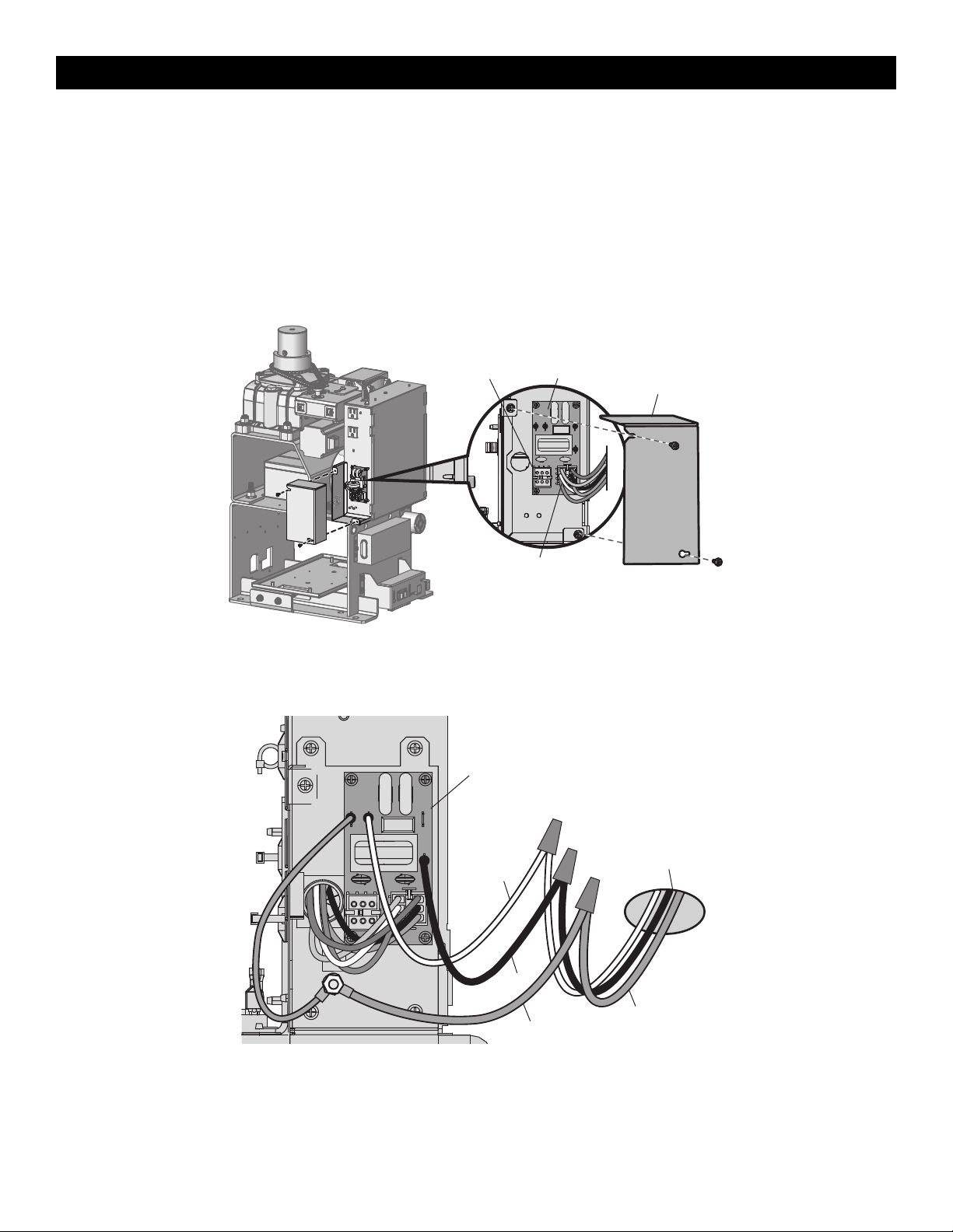
All control wiring used to connect external devices to Class 2 circuits of the operator must be (QPTZ) Power-Limited Circuit Cables, Type CL2, CL2P,
CL2R, or CL2X or other cable with equivalent or better electrical, mechanical, and flammability ratings.
1. Turn off the AC power from the main power source circuit breaker.
2. Run the AC power wires to the operator.
3. Make sure the operator AC switch is in the OFF position, see page 20.
4. Remove the junction box cover from the electrical box by loosening the screws and sliding the cover to the side.
5.
120 Vac: Factory default is 120 Vac. Skip to 5.
240 Vac: Unplug the power wiring connector from the 120 Vac socket (factory default location) and plug it into the 240 Vac socket.
NOTE: The accessory outlets are disabled and cannot be used with the 240 Vac option.
Power Wiring Connector
(120 Vac Socket factory default)
EMI Board240 Vac Socket
Junction Box Cover
6. Connect the incoming green wire to the green ground wire using a wire nut.
7. Connect the white wire to NEUTRAL using a wire nut.
8. Connect the black wire to HOT using a wire nut.
9. Replace the junction box cover. Ensure the wires are not pinched.
Incoming
Power
White
Black
Green
Green ground wire
EMI Board
INSTALLATION
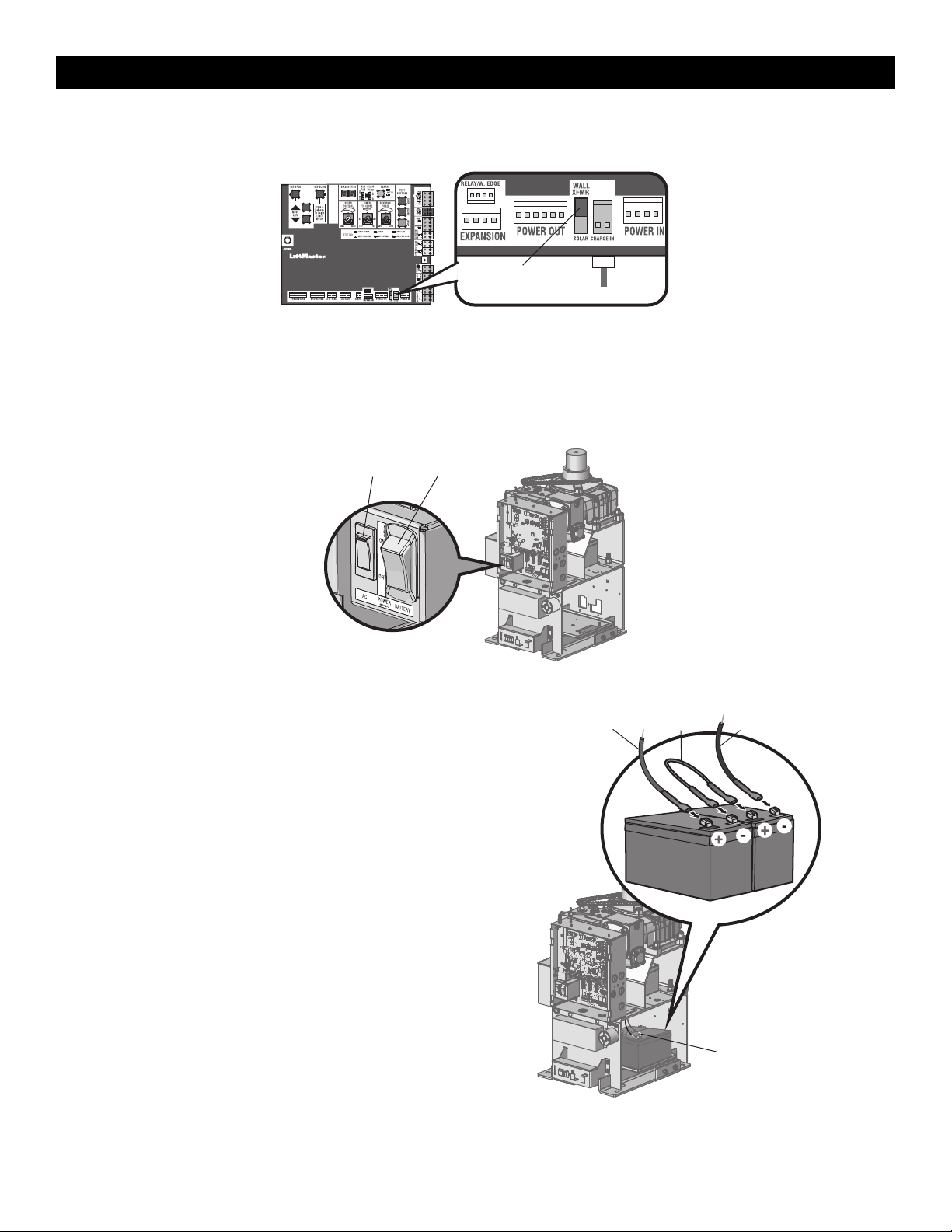
20
Plug In Transformer Power
Wire plug in transformer power as shown.
Plug in transformer
Control Board
Set switch to
WALL XFMR
AC Power Switch
The AC switch on the operator turns the incoming 120/240 Vac power ON or OFF. The AC switch ONLY turns off AC power to the control board and DOES
NOT turn off battery power.
Battery Switch
The battery switch turns the battery power on or off.
AC Power Switch Battery Switch
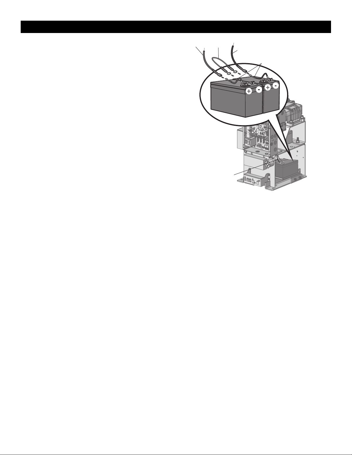
Step 9 Connect Batteries
7AH Batteries
The batteries are charged in the circuit by the integrated transformer.
1. Turn the AC power switch to OFF.
2. Turn the battery switch OFF .
3. Connect a jumper between the positive(+) terminal of the battery to
the negative terminal(-) of the other battery.
4. Connect the red battery wire from the operator to the positive(+)
terminal of the battery.
5. Connect the black battery wire from the operator to the negative (-)
terminal of the battery.
6. Turn the battery switch ON .
7. Turn the AC power switch to ON to restore AC power.
Battery Wiring
Red Wires
Black Wires
Jumper
INSTALLATION
21
33AH Batteries
The batteries are charged in the circuit by the integrated transformer. The
33AH application requires battery harness K41-0102-000 (not provided)
and 33AH battery tray K41-0105-000 (not provided), see Accessories.
1. Turn the AC power switch to OFF.
2. Turn the battery switch OFF.
3. Connect a jumper between the positive(+) terminal of the battery to
the negative terminal(-) of the other battery.
4. Replace the existing battery tray with 33AH battery tray. Place the
batteries in the tray.
5. Connect the (+) terminal of the battery to the red battery wire from
the operator using the RED harness kit wire .
6. Connect the (-) terminal of the battery to the black battery wire from
the operator using the BLACK harness kit wire.
7. Turn the battery switch ON .
8. Turn the AC power switch to ON to restore AC power.
33AH batteries are NOT compatible if transformer kit model 3PHCONV is
installed.
Red Wires
Black Wires
Jumper
Red and Black Wires
Harness Kit Model K42-0102-000
Battery Wiring
INSTALLATION
22
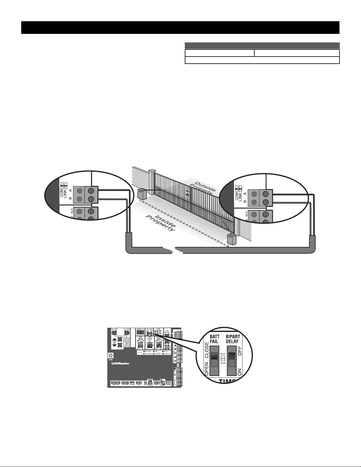
Step 10 Dual Gate setup
There are two options for dual gate communication: wired or wireless. Follow the directions according to your application. Do not use wired and
wireless communication simultaneously. Wired dual gate applications will have a longer battery standby time than wireless applications.
Wireless setup
To activate the wireless feature:
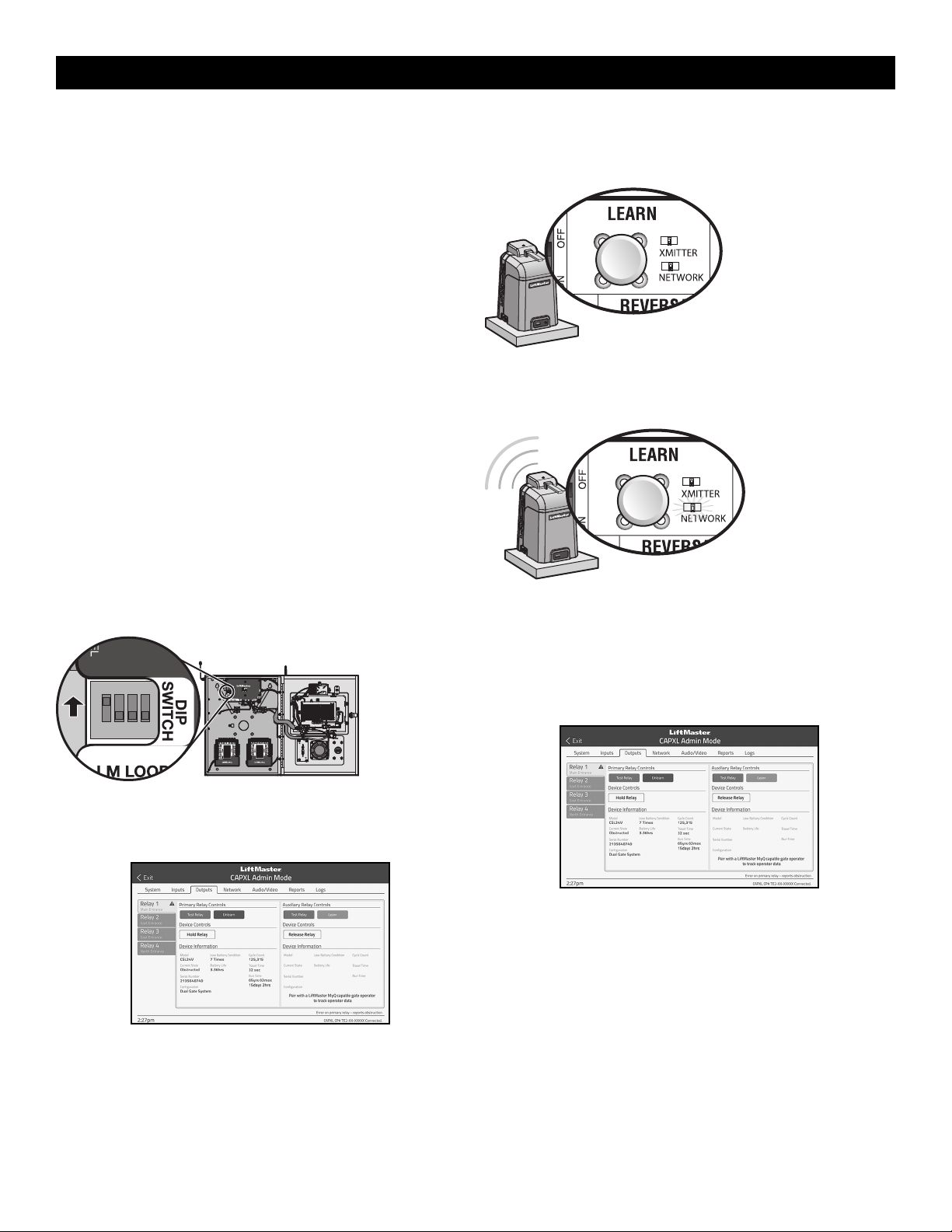
1.
Choose an operator to be the network primary operator. All wireless accessories will need to be programmed to the primary operator. NOTE: We
recommend that all accessories and board configurations are set on the primary operator.
2.
Press and release the LEARN button on the primary operator. The green XMITTER LED will light. NOTE: The operator will time out of programming
mode after 180 seconds.
3. Press and release the LEARN button again on the primary operator. The yellow NETWORK LED will light.
4. Press and release the OPEN test button to assign this operator as network primary.
5. Press and release the LEARN button on the second operator. The green XMITTER LED will light.
6. Press and release the LEARN button again on the second operator. The yellow NETWORK LED will light.
7. Press and release the CLOSE test button to assign this operator as network second.
Both operators will beep and the yellow NETWORK LEDs will turn off indicating programming is successful.
To deactivate the wireless feature:
1. Press and release the LEARN button on either operator. The green XMITTER LED will light.
2. Press and release the LEARN button again on the same operator. The yellow NETWORK LED will light.
3. Press and hold the LEARN button for 5 seconds. The yellow NETWORK LED will blink (operator will beep) then turn off indicating successful
deactivation.
4. Press and release SET OPEN and SET CLOSE buttons simultaneously. The yellow SET OPEN and SET CLOSE LEDs will light.
5. Press and release SET OPEN and SET CLOSE buttons simultaneously again. Both yellow LEDs will turn off and entrapment protection devices will be
relearned.
6. Repeat the steps for the other operator.
Outside
P
roperty
Inside
Property
INSTALLATION
23
Wired setup
Before digging, contact local underground utility locating companies. Use
PVC conduit to prevent damage to cables.
1. Disconnect ALL power to the operator and turn OFF the battery and
AC power switches.
2. Trench across driveway to bury the shielded twisted pair cable.
3. Connect the wires from the shielded twisted pair cable to the Com Link
terminals on the primary gate operator control board. NOTE: We
recommend that all accessories and board configurations are set on
the primary operator.
4. Route the shielded twisted pair cable to the secondary gate operator's
control board.
5. Connect the wires from the shielded twisted pair cable to the Com Link
terminals on the secondary control board (Com Link A to Com Link A
and Com Link B to Com Link B). Ground the shield of the cable to the
chassis ground of one operator.
6. Connect ALL power to the operator and turn ON the battery and AC
power switches.
DUAL GATE WIRE TYPE (SHIELDED TWISTED PAIR CABLE)
22AWG up to 200feet (61m) 18AWG - 200-1000feet (61-305m)
Wire must be rated at 30 Volt minimum
Com Link Data A
Com Link Data B
Com Link Data A
Com Link Data B
Bipart delay/synchronized close
The BIPART DELAY switch is used only with dual gate applications and serves two functions:
•
BIPART DELAY
The BIPART DELAY is used in applications where a maglock, solenoid lock, or decorative overlay would require one gate to close before the other. The
operator with the BIPART DELAY switch ON will delay from the close limit when opening and be the first to close from the open limit.
•
SYNCHRONIZED CLOSE
To synchronize the closing of the gates, set the BIPART DELAY switch to ON for both operators.
INSTALLATION
24
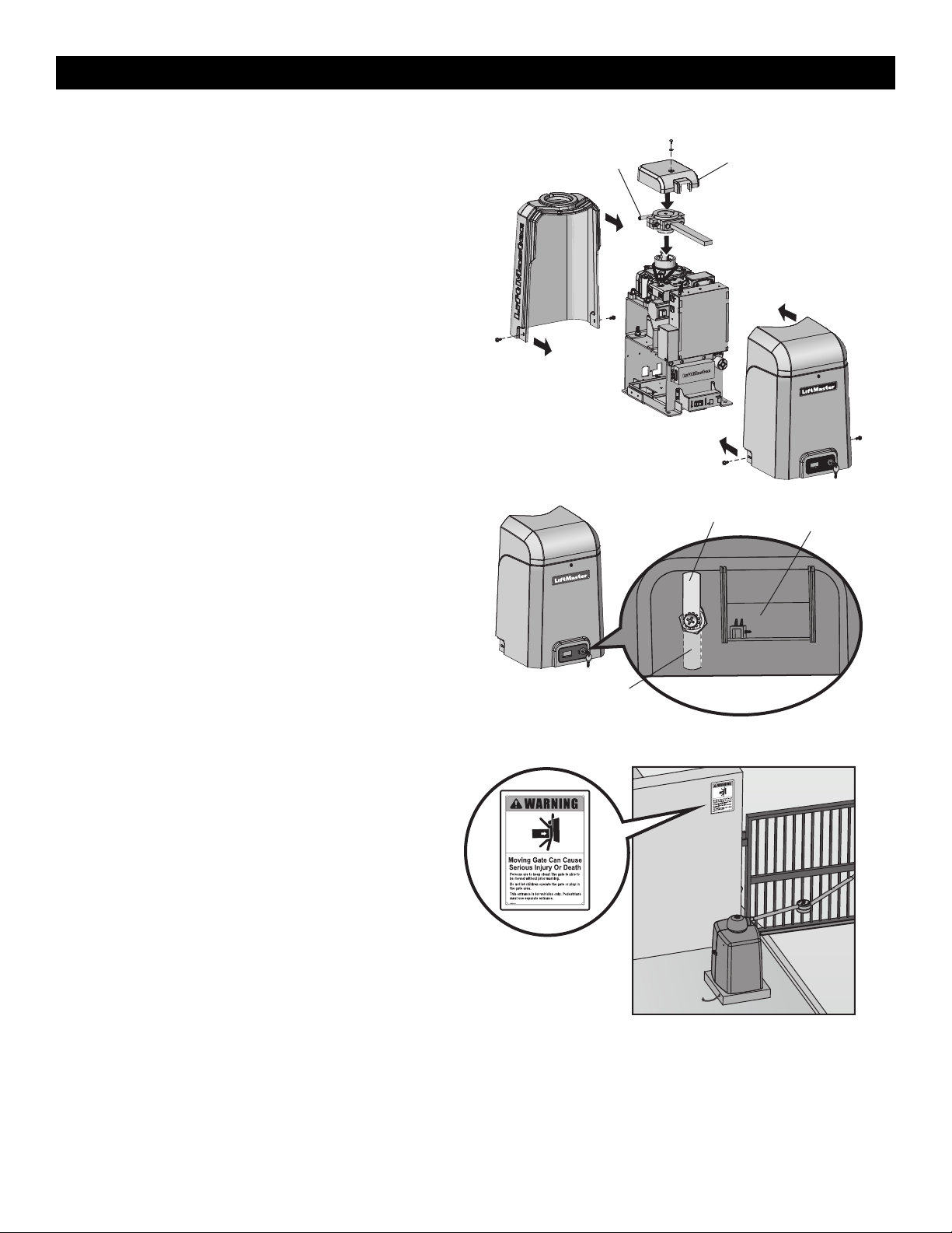
Step 11 Install the Cover
Before installing the cover, follow the instructions in the Adjustment
section to adjust the limits and force.
The operator cover consists of two pieces: a rear cover and a front cover.
The front cover can easily be removed to access the electrical box. Slide
the access door up to access the reset switch. The front cover and access
door can be locked with the key.
1. Remove the operator arm from the output shaft by releasing the
handle.
2. Place the rear cover over the operator.
3. Secure both sides of the rear cover to the chassis with the provided
screws.
4. Reattach the operator arm to the output shaft (making sure the pin
fits into the slot) and secure by pushing the handle down.
5. Place the top (cludge) cover over the operator arm and secure.
6. Align the front cover with the back cover and fit the front cover into
the grooves of the back cover.
7. Secure both sides of the front cover to the chassis with the provided
screws.
Manual Disconnect Handle Top (Cludge) Cover
To Lock the Access Door
From the factory the access door for the reset switch will not be locked.
To lock the access door follow the steps below:
1. Locate the lock tab on the back of the front cover and remove the
screw securing the tab to the cover.
2. Turn the tab 180 degrees, then secure with the screw. The access
door can now be locked.
(back of front cover)
Factory Default Position
Lock Tab
Access Door
Step 12 Install Warning Signs
Installers MUST install the UL required warning signs. The signs MUST
be installed in plain view on both sides of each gate installed. Use the
fastening holes in each corner to permanently secure the sign.
Place warning signs
on both sides of the
gate in clear view
The basic installation is complete.
INSTALLATION
25
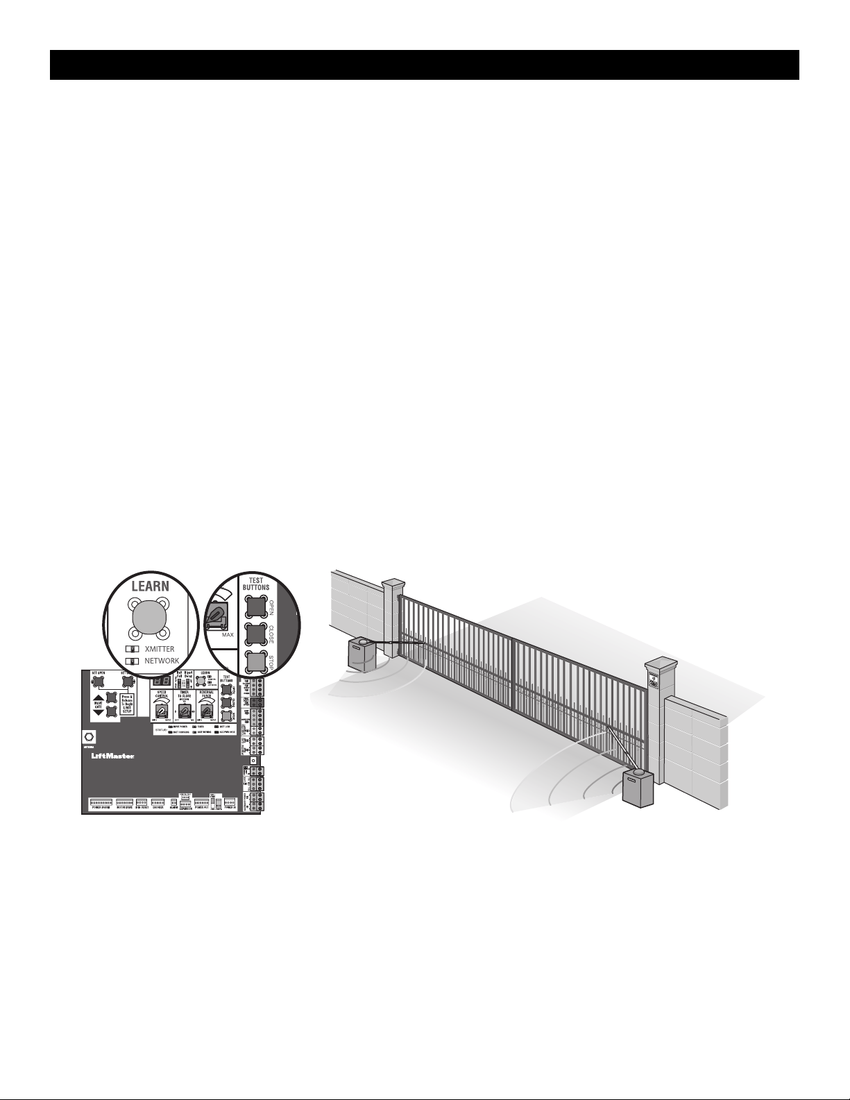
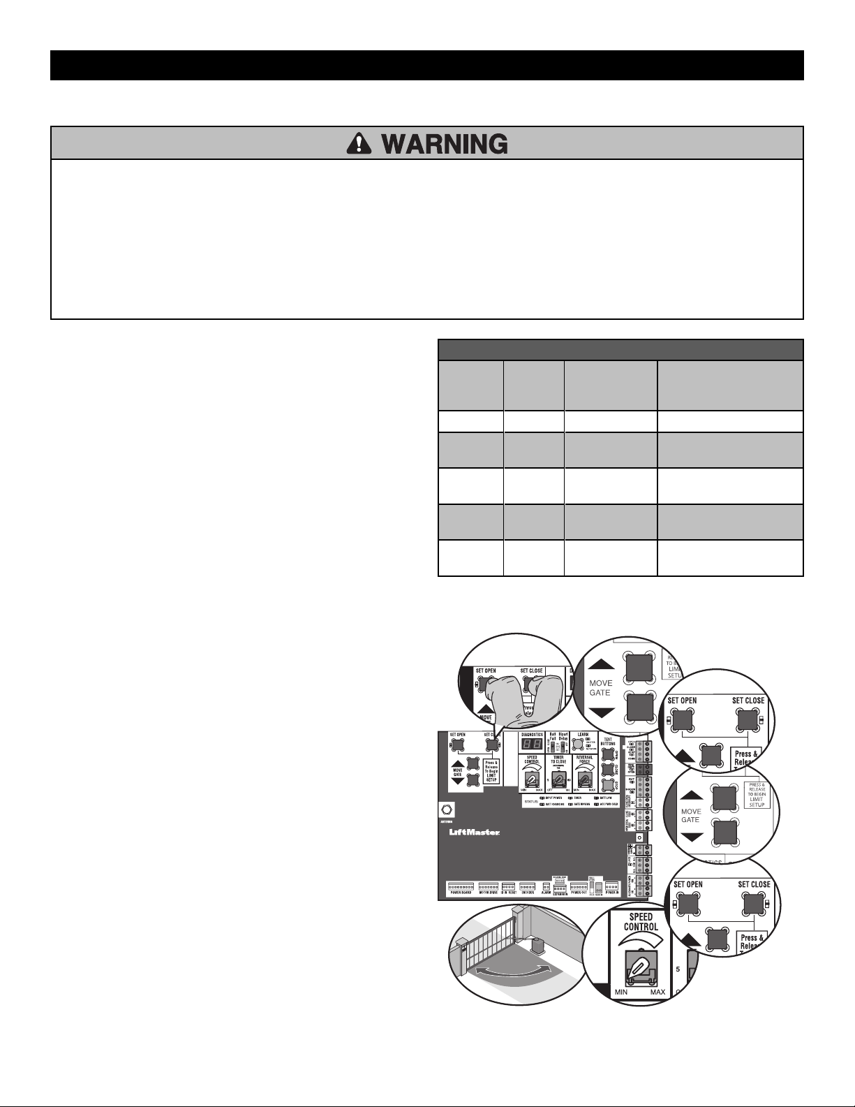
Limit, Speed, and Force Adjustment
To reduce the risk of SEVERE INJURY or DEATH:
• Without a properly installed safety reversal system, persons
(particularly small children) could be SERIOUSLY INJURED or
KILLED by a moving gate.
• Too much force on gate will interfere with proper operation of safety
reversal system.
• NEVER increase force beyond minimum amount required to move
gate.
• NEVER use force adjustments to compensate for a binding or sticking
gate.
• If one control (force, speed or travel limits) is adjusted, the other
controls may also need adjustment.
• After ANY adjustments are made, the safety reversal system MUST be
tested. Gate MUST reverse on contact with an object.
• Faster gate speed increases risk to pedestrians. Use minimum speed
necessary to move gate.
Introduction
Your operator is designed with electronic controls to make travel limit
and force adjustments easy. The adjustments allow you to program
where the gate will stop in the open and close position. The electronic
controls sense the amount of force required to open and close the gate.
The force is adjusted automatically when you program the limits but
should be fine tuned using the REVERSAL FORCE dial on the control
board (refer to Fine Tune the Force section) to compensate for
environmental changes. The limit setup LEDs (located next to the SET
OPEN and SET CLOSE buttons) indicate the status of the limits, refer to
the table to the right.
The limits can be set using the control board (below) or a remote control
(refer to Limit Setup with a Remote Control in the Appendix). Setting the
limits with a remote control requires a 3-button remote control
programmed to OPEN, CLOSE, and STOP.
NOTE: The TEST buttons on the control board will not work until the
limits have been set and the required entrapment protection devices are
installed.
LIMIT SETUP LEDS
SET
OPEN
LED
SET
CLOSE
LED
OPERATOR
MODE
EXPLANATION
OFF OFF NORMAL MODE Limits are set
BLINKING BLINKING LIMIT SETTING
MODE
Limits are not set
BLINKING ON LIMIT SETTING
MODE
Open limit is not set
ON BLINKING LIMIT SETTING
MODE
Close limit is not set
ON ON LIMIT SETTING
MODE
Limits are set
Set the Initial Limits, Speed, and Force
For dual gate applications the limits will have to be set for each
operator. The gate MUST be attached to the operator before setting
the limits and force.
1. Press and release the SET OPEN and SET CLOSE buttons
simultaneously to enter limit setting mode.
2. Press and hold one of the MOVE GATE buttons to move the gate to
the open or close limit.
3. Press and release the SET CLOSE or SET OPEN button depending
on which limit is being set.
4. Press and hold one of the MOVE GATE button to move the gate to
the other limit.
5. Press and release the SET CLOSE or SET OPEN button depending
on which limit is being set.
6. Set the speed dial for the desired 90 degree travel time setting,
13-36 seconds, see page 26.
NOTE: Travel time will vary based on arm configuration
7. Cycle the gate open and close. This automatically sets the force.
When limits are set properly the operator will automatically exit limit
setting mode.
6
7
21
5
4
3
ADJUSTMENT
26
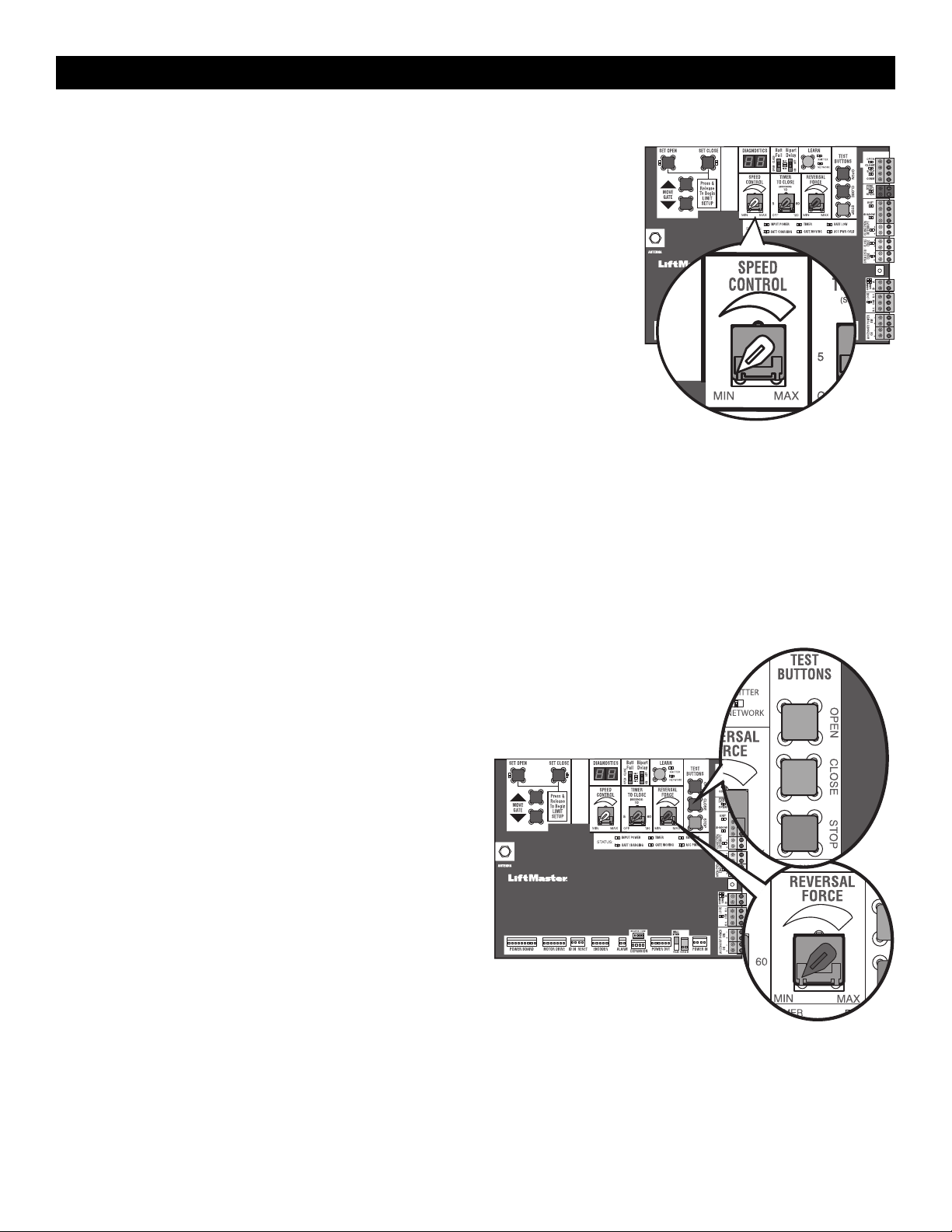
Speed Control
The SPEED CONTROL dial controls the speed of the operator. The dial is
preset to minimum from the factory. Set the speed as low as possible for
the intended application.
90 degree travel time = 13-36 seconds.
NOTE: travel time will vary based on arm configuration. See page 12.
For dual gate setup, set the SPEED CONTROL dial on each operator to the
same setting or make sure the gate that closes first is set faster than the
second operator for smoothest operation.
After any speed adjustment:
1. Cycle the gate open and close to automatically relearn the forces.
2. Perform the Obstruction Test, see page 27.
Fine Tune the Force
Once the initial limits have been set, the REVERSAL FORCE DIAL on the control board is used for fine tuning the force where wind or environmental
changes may affect the gate travel. The REVERSAL FORCE DIAL is set to minimum at the factory.
Based on the length and weight of the gate it may be necessary to make additional force adjustments. The force setting should be high enough that the gate
will not reverse by itself nor cause nuisance interruptions, but low enough to prevent serious injury to a person. The force setting is the same for both the
open and close gate directions.
1. Open and close the gate with the TEST BUTTONS.
2. If the gate stops or reverses before reaching the fully open or closed position, increase the force by turning the force control slightly clockwise.
3. Perform the “Obstruction Test” after every limit, speed, and force setting adjustment see page 27.
ADJUSTMENT
27
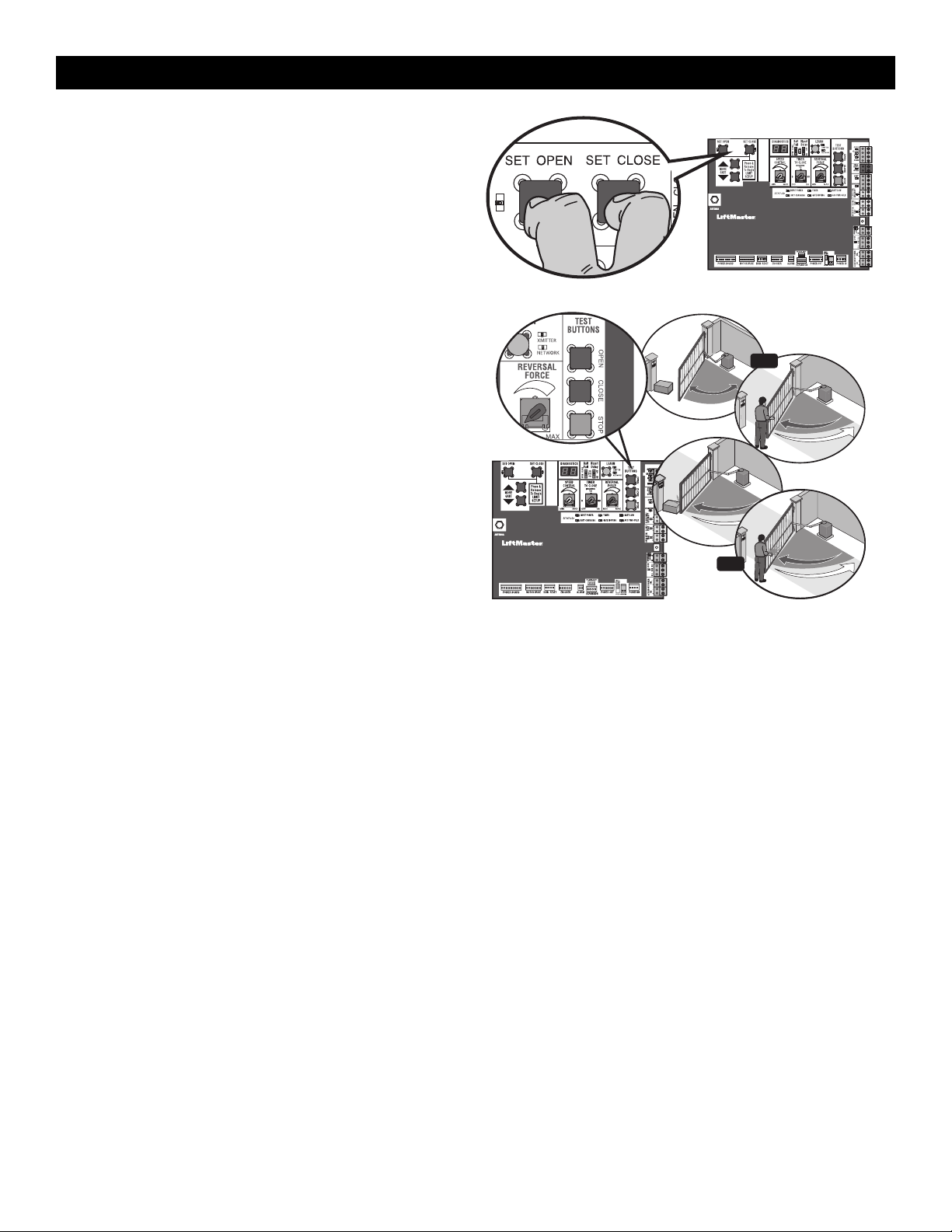
Adjust the Limits
After both limits are set and the operator is ready to run, one limit can be
adjusted independently from the other by following steps 1-3 of the
Initial Limit and Force Adjustment section.
After any limit adjustment:
1. Cycle the gate open and close to automatically relearn the forces.
2. Perform the Obstruction Test, see page 27.
Obstruction Test
The operator is equipped with an inherent (built in to the operator)
obstruction sensing device. If the gate encounters an obstruction during
motion, the operator will reverse direction of the gate and then stop. The
following procedure will test ONLY the inherent (built in to the operator)
obstruction sensing device:
1. Open and close the gate with the TEST BUTTONS, ensuring that the
gate is stopping at the proper open and close limit positions.
2. Either place an object between the open gate and the fixed closed
catch post or obstruct the gate by hand. Make sure that any external
entrapment protection devices, such as an edge or photoelectric
sensor will NOT be activated by the object or by hand.
3. Run the gate in the close direction. The gate should stop and reverse
upon contact with the object or hand. If the gate does not reverse,
reduce the force setting by turning the force control slightly counter-
clockwise. The gate should have enough force to reach both the
open and close limits, but MUST reverse after contact with an object
or hand.
4. Repeat the test for the open direction.
Test the operator after any adjustments are made.
3
1
2
OR
OR
ADJUSTMENT
28
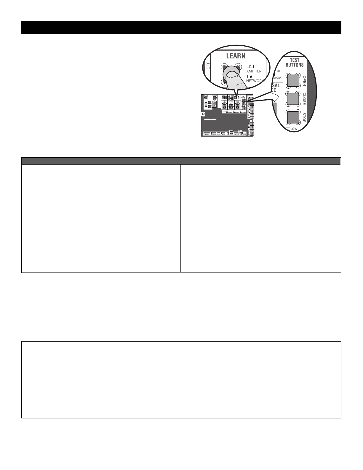
Remote Controls (Not Provided)
A total of 50 Security+ 2.0
®
remote controls or KPW250 keypads and 2
keyless entries (1 PIN for each keyless entry) can be programmed to the
operator. When programming a third keyless entry to the operator, the
first keyless entry will be erased to allow the third keyless entry to be
programmed. When the operator’s memory is full it will exit the
programming mode and the remote control will not be programmed. The
memory will need to be erased before programming any additional
remote controls. NOTE: If installing an 86LM to extend the range of the
remote controls DO NOT straighten the antenna.
There are 3 different options for programming the remote control depending on how you would like the remote control to function. Choose a
programming option:
OPTION DESCRIPTION PROGRAMMING STEPS
Single button as OPEN
only
Program a single button on the remote
control for open only. The Timer-to-Close
can be set to close the gate.
1. Press and release the LEARN button (operator will beep and green
XMITTER LED will light). NOTE: The operator will time out of
programming mode after 30 seconds.
2. Press the OPEN button.
3. Press the remote control button that you would like to program.
Single button (SBC) as
OPEN, CLOSE, and STOP
Program one remote control button as an
open, close, and stop.
1. Press and release the LEARN button (operator will beep and green
XMITTER LED will light). NOTE: The operator will time out of
programming mode after 30 seconds.
2. Press the remote control button that you would like to program.
Three separate buttons as
OPEN, CLOSE, and STOP
Program each remote control button as an
open, close, and stop.
1. Press and release the LEARN button (operator will beep and green
XMITTER LED will light). NOTE: The operator will time out of
programming mode after 30 seconds.
2. Press the OPEN, CLOSE, or STOP button, depending on the desired
function.
3. Press the remote control button that you would like to program.
The operator will automatically exit learn mode (operator will beep and green XMITTER LED will go out) if programming is successful. To program
additional Security+ 2.0
®
remote controls or remote control buttons, repeat the programming steps above.
Entering programming mode using external reset switch or 3-button control station:
1. Make sure gate/door is closed.
2. Give the operator an OPEN command.
3. To put the operator into high band programming mode, give the operator an OPEN command. Within 30 seconds, when the gate is at the open limit,
toggle the reset switch between RESET and NORMAL OPERATION three times or push the button on the control station three times. NOTE: The
operator will time out of programming mode after 30 seconds.
NOTICE: This device complies with Part 15 of the FCC rules and Industry Canada’s license-exempt RSSs. Operation is subject to the following two conditions: (1) this device may not cause
harmful interference, and (2) this device must accept any interference received, including interference that may cause undesired operation.
Any changes or modifications not expressly approved by the party responsible for compliance could void the user’s authority to operate the equipment.
This device must be installed to ensure a minimum 20 cm (8 in.) distance is maintained between users/bystanders and device.
This device has been tested and found to comply with the limits for a Class B digital device, pursuant to part 15 of the FCC rules and Industry Canada ICES standard. These limits are designed
to provide reasonable protection against harmful interference in a residential installation. This equipment generates, uses and can radiate radio frequency energy and, if not installed and used
in accordance with the instructions, may cause harmful interference to radio communications. However, there is no guarantee that interference will not occur in a particular installation. If this
equipment does cause harmful interference to radio or television reception, which can be determined by turning the equipment off and on, the user is encouraged to try to correct the
interference by one or more of the following measures:
- Reorient or relocate the receiving antenna.
- Increase the separation between the equipment and receiver.
- Connect the equipment into an outlet on a circuit different from that to which the receiver is connected.
- Consult the dealer or an experienced radio/TV technician for help.
PROGRAMMING
29
LiftMaster Internet Gateway
(notprovided)
To program the operator to the LiftMaster Internet Gateway:
1. Connect the ethernet cable to the LiftMaster Internet Gateway and the
router.
2. Connect power to the LiftMaster Internet Gateway.
3. Download the myQ
®
App.
4. Set up an account and follow the app instructions to add your gate
operator.
5. The LiftMaster Internet Gateway will pair to the operator if it is within
range and the operator will beep if programming is successful.
The gate operator can then be controlled through the myQ
®
App.
CAPXL Connected Access Portal
The CAPXL can communicate wirelessly to LiftMaster
®
UL325 2016 gate
operators to send open commands, monitor gate position, and send email
notifications if an error occurs in the operator (email notifications are
configured in myQ
®
Business™). Up to 8 gate operators can be paired with
the CAPXL - one for each primary and auxiliary relay. If using dual gates,
program the CAPXL to the primary operator.
To Program the CAPXL:
1. Enter Admin Mode - Flip dipswitch #1 to the ON position to enter
Admin Mode. NOTE: For new installations press the login button
without entering information in the Admin Username and Admin
Password fields.
CAPXL
ON
ON
2. Select Outputs and Relay - Select the Outputs tab. Then select the
desired relay on the left-hand side (1 through 4).
3. Press LEARN button on gate operator - Press and release the LEARN
button on the primary operator. The green XMITTER LED will light.
NOTE: The operator will time out of programming mode after 180
seconds.
4. Press LEARN button on gate operator again - Press and release the
LEARN button again on the primary operator. The yellow NETWORK
LED will light.
5. Select LEARN on display - Select the LEARN button on the display and
the Learn button will go from blue to red. The gate operator and the
CAPXL will beep once and the NETWORK LED on the gate operator
will turn off indicating programming is successful. NOTE: 4
beeps/blinks indicate you are not programming to the primary
operator. Reattempt programming from the other operator.
PROGRAMMING

30
6. Validate - Validate functionality by selecting Test Relay on the CAPXL
display.
For more information refer to the CAPXL documentation.
myQ
®
Business™:
To find out more on how to simply secure all of your access points with an
easy to manage integrated system, myQ Business, please visit:
www.myqbusiness.com.
Erase All Codes
1. Press and release the LEARN button (operator will beep and green
XMITTER LED will light).
2. Press and hold the LEARN button again until the green XMITTER LED
flashes and then release the button (approximately 6 seconds). All
remote control codes are now erased.
Erase Limits
1. To erase the limits, press and hold the SET OPEN and SET CLOSE
buttons simultaneously (5 seconds) until both the SET OPEN and SET
CLOSE LEDs blink rapidly and the operator beeps.
2. Release the buttons and the SET OPEN and SET CLOSE LEDs will blink
slowly indicating the limits will need to be set.
Constant Pressure Override (CPO)
Constant Pressure Override is for use with KPW5 and KPW250 keypads
(not provided). The KPW5/KPW250 wireless commercial keypads are
security keypads and can only be programmed to ONE gate operator (see
the KPW5/KPW250 manual for complete programming instructions).
The Constant Pressure Override feature is intended to temporarily override a
fault in the entrapment protection system, in order to operate the gate until
the external entrapment protection device is realigned or repaired. Use the
feature only in line of sight of the gate when no obstructions to travel are
present. External entrapment protection devices include LiftMaster
monitored photoelectric sensors and LiftMaster monitored wired and
wireless edge sensors. Be sure to repair or replace these devices promptly if
they are not working properly.
To use Constant Pressure Override:
1. Enter a valid 4-digit PIN.
2. Press and hold # for 5 seconds to enter CPO. Continue to hold # to
keep the operator in motion. A continuous tone will sound until limit is
met and/or # is released.
3. The operator will stop when either the operator reaches a limit or the
user releases #.
Gate Hold Open Feature
The gate hold open feature will disable the timer and keep the gate at the
open limit. The gate hold open feature can be activated with the reset
switch, see page 33 or on the KPW5 and KPW250 keypads (not provided).
To use the gate hold open feature on a keypad:
1. Enter a valid 4-digit PIN when the gate is at the open limit and the timer
is running
2. The operator will chirp indicating the timer is canceled.
To restart the gate:
1. Re-enter the 4-digit PIN
2. Activate a hard input or a programmed remote
To Remove and Erase Monitored
Entrapment Protection Devices
1. Remove the entrapment protection device wires from the terminal
block.
2. Press and release the SET OPEN and SET CLOSE buttons
simultaneously. The SET OPEN and SET CLOSE LEDs will turn on
(entering learn limit mode).
3. Press and release both SET OPEN and SET CLOSE buttons again to
turn off the SET OPEN and SET CLOSE LEDs (exiting learn limit
mode).
PROGRAMMING

31
Gate Operator Setup Examples
The following are example setups for the gate operator. Your specific site requirements may be different. Always setup the operator system to the site
requirements, including all necessary entrapment protection devices.
RESIDENTIAL: One to four residential homes sharing a gated entrance/exit, allowing vehicle access trumps security concerns
COMMERCIAL/GENERAL ACCESS: A residential community (more than four homes) having one or more gated entrances/exits, allowing vehicle access
trumps security concerns
COMMERCIAL: Business site where security (gate closed) is important
INDUSTRIAL: Large business site where security is required
SETTING RESIDENTIAL
COMMERCIAL/GENERAL
ACCESS
COMMERCIAL INDUSTRIAL
Quick Close switch
setting
Normally set to OFF. Normal gate
close (timer or control).
Normally set to OFF. Normal gate
close (timer or control).
Normally set to OFF. Normal gate
close (timer or control).
Set to ON, so that gate closes
immediately after vehicle passes
CLOSE EYES/Interrupt loop.
AC Fail Open switch
setting
Normally set to BATT. Run on
battery if AC power fails.
Normally set to BATT. For local
jurisdiction requirement, set to
OPEN so that the gate will open
approximately 15 seconds after AC
power fail.
Normally set to BATT. Run on
battery if AC power fails.
Normally set to BATT. Run on
battery if AC power fails.
Low Battery switch
setting
Normally set to OPEN. If powered
from battery and battery is low,
gate automatically opens and stays
open.
Normally set to OPEN. If powered
from battery and battery is low,
gate automatically opens and stays
open.
Normally set to CLOSE. If powered
from battery and battery is low,
gate stays closed.
Normally set to CLOSE. If powered
from battery and battery is low,
gate stays closed.
Anti-Tail switch setting
Normally set to OFF. CLOSE
EYES/Interrupt loop reverses a
closing gate.
Normally set to OFF. CLOSE
EYES/Interrupt loop reverses a
closing gate.
Set to ON. In attempt to prevent
vehicle tail-gating, CLOSE EYES/
Interrupt loop pauses a closing
gate.
Set to ON. In attempt to prevent
vehicle tail-gating, CLOSE EYES/
Interrupt loop pauses a closing
gate.
Bipart Delay switch
setting
For DUAL-GATE site, set to ON for
gate that delays upon opening.
For DUAL-GATE site, set to ON for
gate that delays upon opening.
For DUAL-GATE site, set to ON for
gate that delays upon opening.
For DUAL-GATE site, set to ON for
gate that delays upon opening.
Aux Relay Out – Open
Limit Switch
Typically not required. Use with SAMS (Sequence Access
Management System).
1. Use with SAMS (Sequence
Access Management
System).
2. Connect “Gate Open”
indicator (e.g. light).
1. Use with SAMS (Sequence
Access Management
System).
2. Connect “Gate Open”
indicator (e.g. light).
Aux Relay Out – Close
Limit Switch
Typically not required. Typically not required. Connect “Gate Close/Secure”
indicator (e.g. light).
Connect “Gate Close/Secure”
indicator (e.g. light).
Aux Relay Out – Gate
Motion
Attach alert signal (audible or
visual alert system).
Attach alert signal (audible or
visual alert system).
Attach alert signal (audible or
visual alert system).
Attach alert signal (audible or
visual alert system).
Aux Relay Out – Pre-
Motion Delay
Attach alert signal (audible or
visual alert system).
Attach alert signal (audible or
visual alert system).
Attach alert signal (audible or
visual alert system).
Attach alert signal (audible or
visual alert system).
Aux Relay Out – Power
Attach visual alert to know when
system is charging batteries (i.e.
not running on batteries).
Attach visual alert to know when
system is charging batteries (i.e.
not running on batteries).
Attach visual alert to know when
system is charging batteries (i.e.
not running on batteries).
Attach visual alert to know when
system is charging batteries (i.e.
not running on batteries).
Cycle Quantity Feedback
Use during servicing only to
determine operator cycles.
Use during servicing only to
determine operator cycles.
Use during servicing only to
determine operator cycles.
Use during servicing only to
determine operator cycles.
Fire Dept Open Input
Typically not required. Connect emergency access
system (Knox box switch, SOS
system, etc.).
Typically not required. Typically not required.
Heater Accessory
(Model HTR)
The heater keeps the gearbox and
batteries at a suitable temperature
when the outside temperature is
below -4°F. The thermostat MUST
be set between 45°F and 60°F to
ensure proper gate operation.
The heater keeps the gearbox and
batteries at a suitable temperature
when the outside temperature is
below -4°F. The thermostat MUST
be set between 45°F and 60°F to
ensure proper gate operation.
The heater keeps the gearbox and
batteries at a suitable temperature
when the outside temperature is
below -4°F. The thermostat MUST
be set between 45°F and 60°F to
ensure proper gate operation.
The heater keeps the gearbox and
batteries at a suitable temperature
when the outside temperature is
below -4°F. The thermostat MUST
be set between 45°F and 60°F to
ensure proper gate operation.
OPERATION
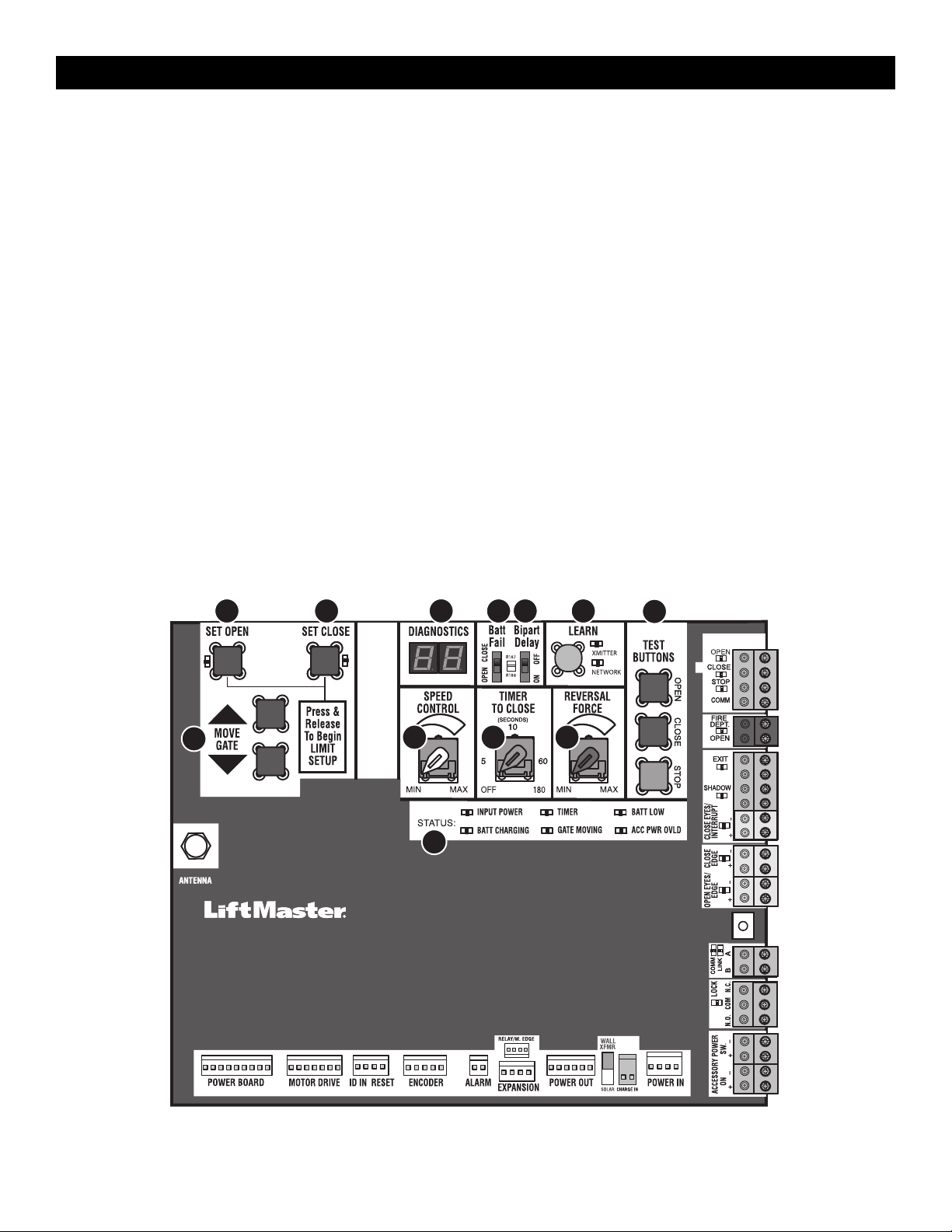
32
Control Board Overview
1 SET OPEN Button: The SET OPEN button sets the OPEN limit. See Adjustment section.
2 SET CLOSE Button: The SET CLOSE button sets the CLOSE limit. See Adjustment section.
3 DIAGNOSTICS Display: The diagnostics display will show the operator type, firmware version, and codes. The operator type will display as "HG" followed
by a "24" which indicates the operator type as HDSW24UL. The firmware version will show after the operator type, example "1.2".
4 BATT FAIL:
• When AC power is OFF and battery voltage is critically low the gate will latch at a limit until AC power is restored or batteries voltage increases.
• Option select switch set to OPEN forces gate to automatically open and then latch at the OPEN limit until AC power is restored or battery voltage
increases.
• Option select switch set to CLOSE forces gate to latch at CLOSE limit if at CLOSE limit or on next CLOSE command until AC power restored or battery
voltage increases.
• Constant pressure on a hard command input overrides to open or close the gate.
• Critically low battery is less than 23 Vdc.
5 BIPART DELAY Switch: The LOCK/BIPART DELAY switch is used only for dual gates. See Bipart delay/synchronized closed page 22.
6 LEARN Button: The LEARN button is for programming remote controls and the network.
7 TEST BUTTONS: The TEST BUTTONS will operate the gate (OPEN, STOP and CLOSE).
8 MOVE GATE Buttons: The MOVE GATE buttons will either open or close the gate when the operator is in Limit setting mode. See Adjustment section.
9 SPEED CONTROL dial: Sets maximum gate speed, see Speed Control page 26.
10 TIMER-TO-CLOSE dial: The TIMER-TO-CLOSE (TTC) dial can be set to automatically close the gate after a specified time period. The TTC is factory set
to OFF. If the TTC is set to the OFF position, then the gate will remain open until the operator receives another command from a control. Rotate the TIMER-
TO-CLOSE dial to the desired setting. The range is 0 to 180 seconds, 0 seconds is OFF. NOTE: Any radio command, single button control, or CLOSE
command on the control board prior to the TTC expiring will close the gate. The TTC is reset by any signals from the open controls, loops, close edges,
and close photoelectric sensors (IR’s).
11 REVERSAL FORCE dial: The REVERSAL FORCE dial fine tunes the force, see Fine Tune the Force page 26.
12 STATUS LEDs: The STATUS LEDs indicate the status of the operator. See Status LED Chart in the Troubleshooting section.
1 2 4 5 6
9
3
12
10 11
7
8
OPERATION
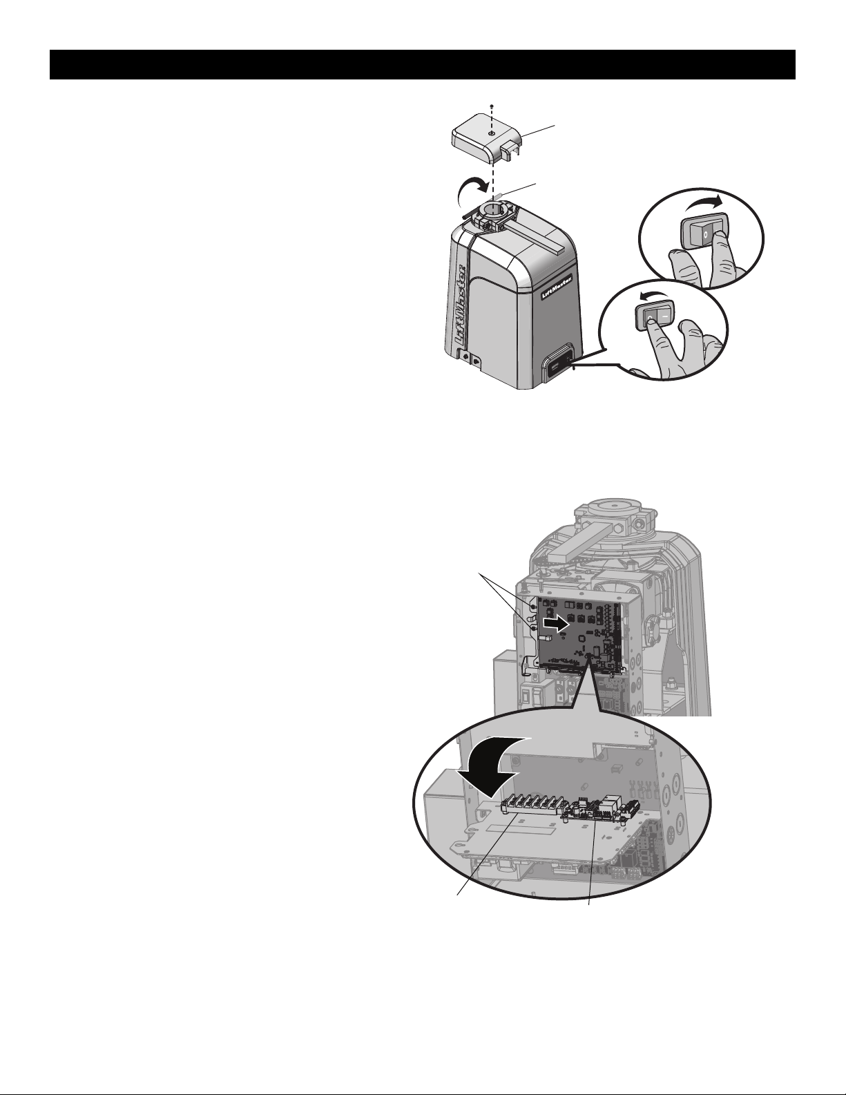
33
Manual Disconnect
1. Set the reset switch to the RESET position.
2. Remove the top (cludge) cover.
3. Rotate the manual disconnect handle 180°.
On a dual gate application the handle must be released on both
operators. To resume normal function, rotate the manual disconnect
handle back and push it down. Set the switch back to NORMAL
OPERATION. Replace top (cludge) cover and secure with screw.
Reset Switch
The reset switch has the following functions:
• Set the switch to the RESET position to disable gate operation. Use
this switch before servicing the gate or manually disconnecting the
gate. The stop LED will be illuminated.
• To hold the gate open, run the gate to the open position and then set
the switch to the RESET position.
• Toggle the reset switch to RESET then back to NORMAL OPERATION
when the operator alarm has been set off, see page 34.
• To put the operator into high band programming mode, give the
operator an OPEN command. Within 30 seconds, when the gate is at
the open limit, toggle the reset switch between RESET and NORMAL
OPERATION three times.
Reset/
Disconnect
Normal Operation
Manual Disconnect
Handle
Top (Cludge) Cover
Relay Adapter Board and Terminal
Block Access
To access the relay adapter board and terminal block, loosen the two
screws of the control board bracket, slide the whole bracket to the right,
then swing open.
Screws
Terminal Block
Relay Adapter Board
OPERATION
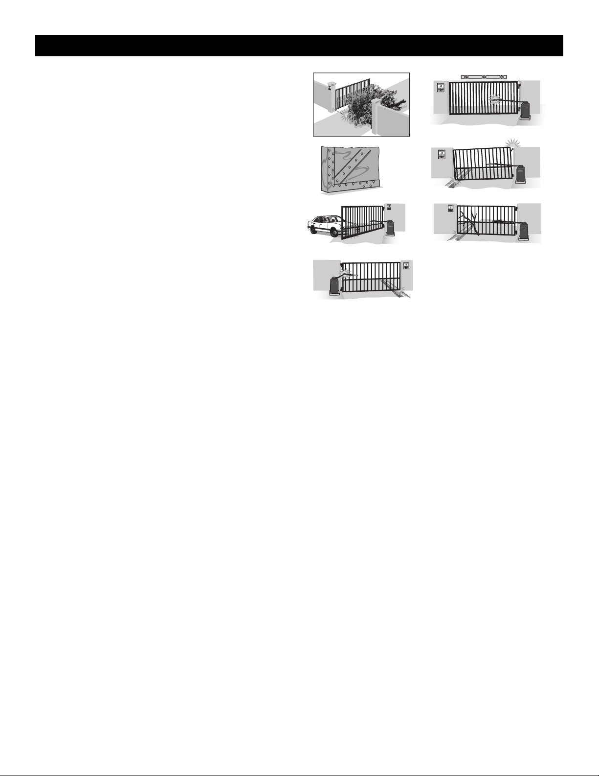
34
Operator Alarm
When the inherent force of the operator detects the following twice
consecutively, the alarm will sound up to 5 minutes and the operator will
need to be reset.
A. The gate is hitting an obstruction.
B. The operator arm or gate is incorrectly installed.
C. The gate does not meet specifications.
D. Gate hinges are too tight or broken and the gate is not moving freely.
E. The gate is moving and a car pushes the gate.
F. A foreign object is on the gate frame while the gate is moving.
G. The gate hits the driveway or curb and gets stuck or bent in an
awkward position.
The operator alarm will beep 3 times with a command if the battery is
low.
Remove any obstructions or repair gate system. Toggle the reset switch
to RESET then back to NORMAL OPERATION to shut off the alarm and
reset the operator. After the operator is reset, normal functions will
resume.
F
G
E
C D
BA
Remote control
Single Button Control (SBC) Functionality
Once the remote control has been programmed the operator will operate as follows:
When gate is in the closed position, activation of the remote control button will open the gate. During the open cycle another activation of the remote
control will stop the gate and the next activation of the remote control will close the gate.
When the gate is in the open position, activation of the remote control button will close the gate. If the remote control is activated while the gate is closing,
the gate will stop and the next activation will open the gate.
OPERATION
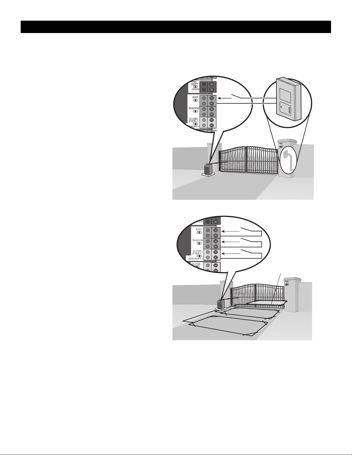
35
All control wiring used to connect external devices to Class 2 circuits of the operator must be (QPTZ) Power-Limited Circuit Cables, Type CL2, CL2P,
CL2R, or CL2X or other cable with equivalent or better electrical, mechanical, and flammability ratings.
External Control Devices
NOT TO BE USED AS ENTRAPMENT PROTECTION
EXIT (2 Terminals)
This input is a soft open command (maintained switch does not override
external safeties and does not reset alarm condition). Used for exit probe,
telephone entry, external exit loop detector, or any device that would
command the gate to open.
• Opens a closed or closing gate and holds open an open gate, if
maintained, pauses Timer-to-Close at OPEN limit.
SHADOW (2 Terminals)
This input is used for external shadow loop detector when loop is
positioned under the swing of the gate.
• Holds open gate at open limit
• Only active when the gate is at the OPEN limit, disregarded at all
other times
• Pauses Timer-to-Close at OPEN limit
INTERRUPT (2 Terminals)
This input is used for an external interrupt loop detector when loop is on
the outside of the gate.
• Holds open gate at open limit
• Stops and reverses a closing gate to open limit
• Pauses Timer-to-Close at OPEN limit, activates quick close and anti-
tailgate features when enabled on the expansion board
Access control device wiring
Access Control Device
Exit
Com
Control board
Loop wiring
Interrupt Loop
Control board
Exit
Com
Shadow
Com
Interrupt
Com
Exit Loop
Shadow Loop
ACCESSORY WIRING
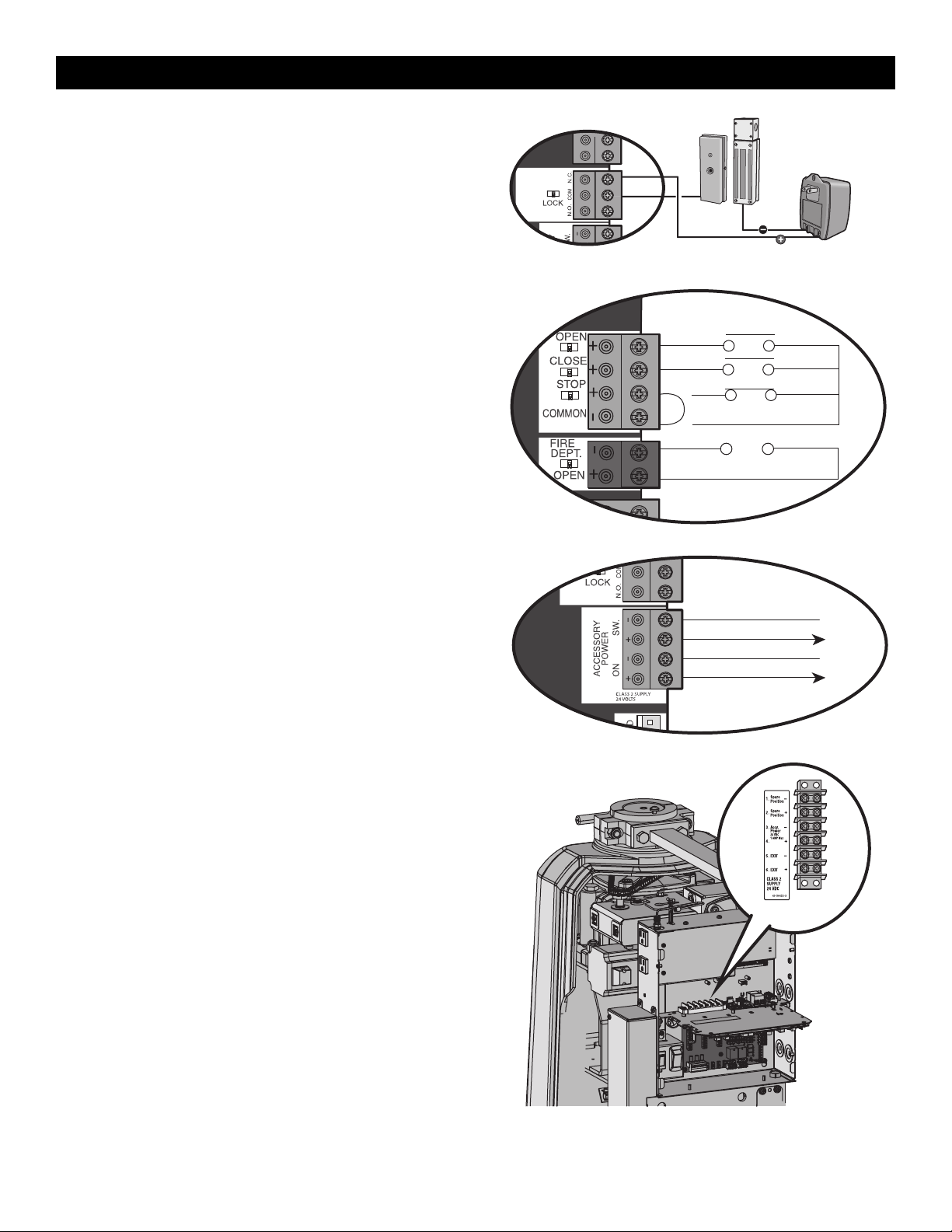
36
Locks
Maglock (2 Terminals, N.C. and COM)
Relay contact output, Normally - closed (N.C.) output for maglocks.
Relay activates prior to motor activation and during motor run. Relay is
off when motor is off.
CONTROL BOARD MAGLOCK
NOT
PROVIDED
Miscellaneous Wiring
Three button control station (4 Terminals)
• OPEN and COM: Opens a closed gate. Hard open (maintained switch
overrides external safeties and resets alarm condition). If maintained, pauses
Timer-to-Close at OPEN limit. Opens a closing gate and holds open an open
gate (within line-of-sight).
• CLOSE and COM: Closes an open gate. Hard close (maintained switch
overrides external safeties and resets alarm condition within line-of-sight)
• STOP and COM: Stops a moving gate. Hard stop (maintained switch
overrides Open and Close commands and resets alarm condition). If
maintained, pauses Timer-to-Close at OPEN limit. Overrides Open and Close
commands (within line-of-sight).
Fire department open input (2 Terminals)
Acts as hard open.
Maintained input overrides (ignores) external safeties (photoelectric sensor and
edge), pauses Timer-to-Close momentary input logic as single button control
and safeties remain active, re-enables Timer-to-Close.
Accessory power class 2 supply 24 VDC, MAX 1 Amp
(4 Terminals)
• SWITCHED: Switched ON with gate motion and at the open limit when
Timer-to-Close is active. Turns off 5 seconds after motion.
• UNSWITCHED: 24 Vdc voltage out to power accessories, always ON.
MAIN CONTROL BOARD
Three Button Control Station
Open
Close
N.C.
Stop
Com
Fire Dept
Com
Fire Department
MAIN CONTROL BOARD
Accessory Power Switched
Com (-)
Acc power +24 Vdc
Com (-)
Acc power +24 Vdc
Accessory Power Unswitched
Terminal Block
The terminal block provides additional space for accessory wiring.
Terminal Block
ACCESSORY WIRING
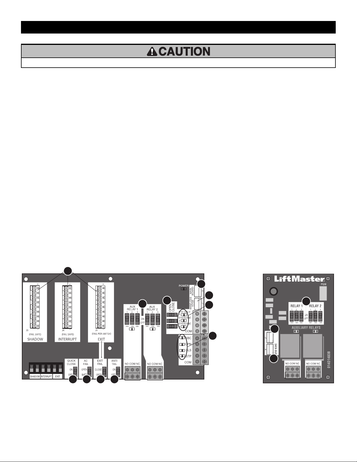
37
• To AVOID damaging the circuit board, relays or accessories, DO NOT connect more than 42 Vdc (32 Vac) to the AUX relay contact terminal blocks.
Expansion and Relay Adapter Boards Overview
1. QUICK CLOSE switch:
OFF: No change to the gate's normal operation.
ON: When CLOSE EYES/Interrupt loop is deactivated it causes an
opening or a stopped gate to close (ignores the Timer-to-Close).
2. AC FAIL switch:
OPEN: Loss of AC power will cause the gate to open approximately 15
seconds after AC power fail and remain OPEN until AC power is
restored (enabling the Timer-to-Close).
BATT: With loss of AC power, gate will remain in present position and
operator is powered from batteries.
3. EXIT FAIL switch:
When set to OPEN, if the EXIT plug-in loop detector (Model
LOOPDETLM) detects a fault, then the gate will open and remain open
until fault is cleared. When set to CLOSE, then plug-in EXIT loop
detector faults are ignored (EXIT loop is faulted and inoperative).
4. ANTI-TAIL switch:
OFF: When CLOSE EYES/Interrupt loop is activated it causes a closing
gate to stop and reverse.
ON: When CLOSE EYES/Interrupt loop is activated it causes a closing
gate to pause. Once the vehicle is clear the gate will continue to close.
5. AUX RELAY switches:
Set the AUX RELAY switches as needed to obtain the desired function
as shown on the following page.
6. EYE/EDGE switches:
Set the EYE/EDGE switches as needed to obtain the desired OPEN or
CLOSE functionality.
7. 1, 2, and 3 LEDs:
LEDs indicating the status of the EYE/EDGE inputs. Also used to check
the firmware version of the expansion board:
1. Locate the 1, 2, and 3 LEDs on the expansion board.
2. Disconnect AC/DC power to the main control board for 15
seconds.
3. Connect power. The 1, 2, and 3 LEDs will flash in sequence until
the main control board firmware revision is displayed. When the
green POWER LED glows solid the LED 1 will flash the version
number, then stop, then the LED 2 will flash the revision number
(for example: For version 5.1 when the green POWER LED is solid
the LED 1 will flash 5 times, then stop, then the LED 2 will flash
once).
8. J6 input:
Communication bus connects control board, expansion board, or relay
adapter board. Also connects LiftMaster wireless edge device
LMWEKITU.
9. Input LEDs:
LEDs indicating the status of the SBC, OPN, CLS, and STP inputs.
10. Loop detector inputs:
Inputs for the Plug-In Loop Detectors (Model LOOPDETLM)
11. J7 input
Communication bus connects control board, expansion board, or relay
adapter board. Also connects LiftMaster wireless edge model
LMWEKITU.
1 2 3 4
6
9
8
11
7
10
5
RELAY ADAPTER BOARDEXPANSION BOARD
8
5
11
EXPANSION AND RELAY ADAPTER BOARDS

38
Auxiliary Relays
The expansion board and relay adapter board provide Normally Open (N.O.) and Normally Closed (N.C.) relay contacts to control external devices, for
connection of Class 2, low voltage (42 Vdc [34 Vac] max 5 Amps) power sources only. Function of relay contact activation determined by switch settings.
AUX RELAY
SETTING
SWITCH SETTINGS
AUX RELAY 1 AUX RELAY 2
1 2 3
Off (no feature
selected)
OFF OFF OFF Relay always off. Use this Aux Relay setting to conserve battery power.
Open Limit Switch
OFF OFF ON Energizes at open limit. Use with SAMS (Sequenced Access Management System, jointly with barrier gate).
Close Limit Switch
OFF ON OFF Energizes when not at close limit. For an additional audible or visual display, connect an external light (low voltage).
Gate Motion
OFF ON ON
Energizes when motor is on (gate in motion). For an additional audible or visual display, connect an external buzzer or light (low
voltage).
Pre-Motion Delay -
Expansion Board Only
ON OFF OFF
Energizes 3 seconds before gate motion and remains energized
during gate motion. The onboard alarm will sound. For an
additional audible or visual display, connect an external buzzer or
light (low voltage).
Energizes 3 seconds before gate motion and remains energized
during gate motion. For an additional audible or visual display,
connect an external buzzer or light (low voltage).
Power
ON ON OFF
Energizes when AC power or solar power is present. There is
approximately a 10-12 second delay before relay cutoff, after AC
shutdown.
Energizes when on battery power. There is approximately a 10-12
second delay before relay cutoff, after AC shutdown.
Tamper
ON OFF ON
Energizes if gate is manually tampered with by being pushed off of close limit. For an additional audible or visual display, connect an
external buzzer or light (low voltage).
Cycle Count - Expansion
Board Only
ON ON ON
The 1, 2, and 3 LEDs will blink out the cycle count (cycle count is
stored on the control board). See below.
Red/green light functionality, see below.
* Cycle count
First, note the current Aux Relay switch positions. To determine the
actual cycles that the gate operator has run (in thousands), set all three
Aux Relay switches to the ON setting for Aux Relay 1. The Expansion
Board’s 1, 2, and 3 LEDs will blink out the cycle count, with 1 LED
blinking 1000’s, 2 LED blinking 10,000’s, 3 LED blinking 100,000’s, and
simultaneously all three LED’s blink 1,000,000’s (e.g. 1 LED blinks 3
times, 2 LED blinks 6 times, and 3 LED blinks once. Cycle count is
163,000.). Cycle count displayed is between 1,000 and 9,999,000 cycles.
After servicing, set Aux Relay switches back to their appropriate
positions. Cycle count cannot be reset or changed. If under 1,000 cycles
the 1, 2, and 3 LEDs will turn on for 10 seconds, then turn off.
NOTE: The expansion board will flash the cycle count 3 times then all the
LEDs will turn on solid for 10 seconds then turn off.
N.O.
Com
N.C.
N.O.
Com
N.C.
EXPANSION BOARD RELAY ADAPTER BOARD
N.O.
Com
N.C.
N.O.
Com
N.C.
RED/GREEN LIGHT FUNCTIONALITY
Red light wired to AUX RELAY 1. Green light wired to AUX RELAY 2.
GATE STATE
AUX RELAY 1 SWITCHES
AUX RELAY 2 SWITCHES
1 OFF 2 OFF 3 OFF 1 ON 2 ON 3 ON
Closed
Red light OFF* Green light OFF
Opening
Red light ON/Flash Green light OFF
Open
Red light OFF Green light ON
Closing
Red light ON/Flash Green light OFF
Defined Mid Stop
n/a n/a
Undefined Mid Stop
Red light ON Green light OFF
Timer more than 5
seconds
Red light OFF Green light ON
Timer less than 5
seconds
Red light ON/Flash Green light OFF
* For red light ON when gate is closed, set switch 1 on AUX RELAY 1 to ON
Control board
Expansion board
RED
COM
GREEN
Red/green light RGL24LY
EXPANSION AND RELAY ADAPTER BOARDS

39
Wiring Accessories to the Expansion Board
Refer to the chart below and the corresponding image for a description of the expansion board inputs.
1 Wireless edge, control board, or
relay adapter board
Connection for wireless edge receiver, control board or relay adapter board.
2 Entrapment Protection Device
Inputs (4 terminals total), Open or
Close Direction based on switch
setting next to inputs
EYES ONLY Input: Open or Close Direction Photoelectric Sensors, Close: reverses fully, Open: reverses 4
seconds
EYES/EDGE Input(s): Open or Close Direction Photoelectric Sensors, Infra-red detector wired or Edge
Sensor, reverses 4 seconds
3 Single Button Control, SBC
(2terminals)
Gate command sequence - Open, Stop, Close, Stop, ... Soft Open ,Soft Close, Soft Stop (maintained
switch does not override external safeties and does not reset alarm condition)
4 Open Input (& common) (3-Button
Control Station, 4 terminals total)
Open command - opens a closed gate.
Soft open (maintained switch does not override external safeties and does not reset alarm condition) If
maintained, pauses Timer-to-Close at OPEN limit.
Opens a closing gate and holds open an open gate.
5 Close Input (& common) (3-Button
Control Station, 4 terminals total)
Close command - closes an open gate.
Soft close (maintained switch does not override external safeties and does not reset alarm condition).
6 Stop Input (& common) (3-PB
station, 4 terminals total)
Stop command - stops a moving gate.
Hard stop (maintained switch overrides Open and Close commands and resets alarm condition) If
maintained, pauses Timer-to-Close at OPEN limit.
Overrides an Open or Close command.
7 Exit Loop Input (2 terminals)
Loop wire connection for plug-in loop detector when loop is inside secured area near gate.
Open command - opens a closed gate.
Soft open (maintained switch does not override external safeties and does not reset alarm condition) If
maintained, pauses Timer-to-Close at OPEN limit.
Opens a closing gate and holds open an open gate.
8 Shadow Loop Input (2 terminals)
Loop wire connection for plug-in loop detector when loop is positioned under the gate.
• Holds open gate at open limit
• Disregarded during gate motion
• Pauses Timer-to-Close at Open Limit
9 Interrupt Loop Input (2 terminals)
Loop wire connection for plug-in loop detector when loop is along the side of the gate.
• Holds open gate at open limit
• Stops and reverses a closing gate
• Pauses Timer-to-Close at Open Limit
Shadow Loop
Interrupt Loop
Exit Loop
Photoelectric Sensor
Photoelectric
Sensor or Edge
Photoelectric
Sensor or Edge
7
6
5
4
3
2
9
8
1
Wireless edge, control board,
or relay adapter board
EXPANSION AND RELAY ADAPTER BOARDS
40
IMPORTANT SAFETY INSTRUCTIONS
To reduce the risk of SEVERE INJURY or DEATH:
• READ AND FOLLOW ALL INSTRUCTIONS.
• ANY maintenance to the operator or in the area near the operator
MUST NOT be performed until disconnecting the electrical power
(AC or solar and battery) and locking-out the power via the operator
power switch. Upon completion of maintenance the area MUST be
cleared and secured, at that time the unit may be returned to service.
• Disconnect power at the fuse box BEFORE proceeding. Operator
MUST be properly grounded and connected in accordance with
national and local electrical codes. NOTE: The operator should be on
a separate fused line of adequate capacity.
• NEVER let children operate or play with gate controls. Keep the
remote control away from children.
• ALWAYS keep people and objects away from the gate. NO ONE
SHOULD CROSS THE PATH OF THE MOVING GATE.
• The entrance is for vehicles ONLY. Pedestrians MUST use separate
entrance.
•
TEST THE GATE OPERATOR MONTHLY. The gate MUST reverse on
contact with an object or reverse when an object activates the
noncontact sensors. After adjusting the force, speed, or the limit of
travel, retest the gate operator. Failure to adjust and retest the gate
operator properly can increase the risk of INJURY or DEATH.
• Use the manual disconnect release ONLY when the gate is NOT
moving.
• KEEP GATES PROPERLY MAINTAINED. Read this manual carefully.
Have a qualified service person make repairs to gate hardware.
• ALL maintenance MUST be performed by a Trained Gate Systems
Technician.
• Activate gate ONLY when it can be seen clearly, is properly adjusted
and there are no obstructions to gate travel.
• To reduce the risk of FIRE or INJURY to persons use ONLY LiftMaster
part 29-NP712 for replacement batteries.
• SAVE THESE INSTRUCTIONS.
• ALWAYS wear protective gloves and eye protection when changing the battery or working around the battery compartment.
MAINTENANCE

41
Maintenance Chart
Disconnect all power (AC, solar, battery) to the operator before servicing.
DESCRIPTION TASK CHECK AT LEAST ONCE EVERY
MONTH 6 MONTHS 3 YEARS
Entrapment Protection Devices
Check and test inherent (built into the operator) and external devices for
proper operation
X
Warning Signs
Make sure they are present and replace if worn or broken, see Accessories
X
Manual Disconnect Check and test for proper operation X
Sprockets and Chain Check for excessive slack and lubricate X
Gate Inspect for wear or damage; ensure it still complies with ASTM F2200, see
page 6
X
Accessories Check all for proper operation X
Electrical Inspect all wire connections X
Chassis Mounting Bolts Check for tightness X
Operator Inspect for wear or damage X
Diagnostic History Review diagnostic history for identification of intermittent problems
X
Batteries Replace
X
NOTES:
• It is suggested that while at the site voltage readings be taken at the operator. Using a digital voltmeter, verify that the incoming voltage to the operator
is within ten percent of the operator’s rating.
Batteries
Batteries will degrade over time depending on temperature and usage.
The operator alarm will beep 3 times with a command if the battery is
low. Batteries do not perform well in extremely cold temperatures. For
best performance, the batteries should be replaced every 3 years. Use
only LiftMaster part 29-NP712 for replacement batteries. The batteries
contain lead and need to be disposed of properly.
The operator comes with two 7AH batteries. Two 33AH batteries
(A12330SGLPK), with battery harness model K41-0102-000 (not
provided), may be used in place of the 7AH batteries.
33AH batteries are NOT compatible if transformer kit model 3PHCONV is
installed.
MAINTENANCE
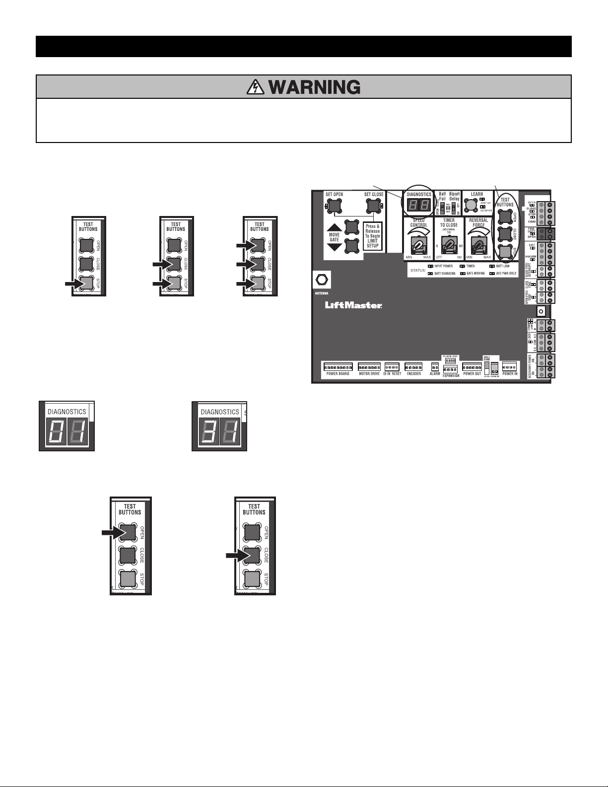
42
To protect against fire and electrocution:
• DISCONNECT power (AC or solar and battery) BEFORE installing or
servicing operator.
For continued protection against fire:
• Replace ONLY with fuse of same type and rating.
Diagnostic Codes
To View the Codes
The codes will show on the diagnostic display.
Press and
hold the
STOP
button...
...then press
and hold the
CLOSE button...
...then press
and hold the
OPEN button
until "Er"
shows on
the display.
The operator will show the code sequence number followed by the code
number:
A SECOND
LATER....
CODE SEQUENCE NUMBER
The first number shown is the
most recent code (example:
"01"). The display will show the
sequence of codes that
occurred starting with "01" and
going up to code "20".
CODE NUMBER
The second number shown after
the code sequence number is
the code itself (31-99, example"
"31"). Refer to the chart on the
following page for an
explanation of each code.
To Scroll Through the Saved Codes
Press the OPEN button
to cycle to the most
recent code ("01").
Press the CLOSE button
to cycle to the oldest
code (up to "20").
The operator will only keep track of up to 20 codes, then will start saving
over the oldest codes as new codes occur.
DIAGNOSTICS DISPLAY
OPEN, CLOSE, & STOP BUTTONS
To Exit
Press and release the STOP button to exit. The display will also time out
after two minutes of inactivity.
To Reset the Code History
1. Press and hold the STOP button for six seconds. The display will
show "Er" then "CL" alternately for six seconds.
2. Release the STOP button. The code history has now been reset and the
display will show "- -" until a new code occurs.
3. Press and release the STOP button to exit.
See the diagnostic codes table page 59.
TROUBLESHOOTING
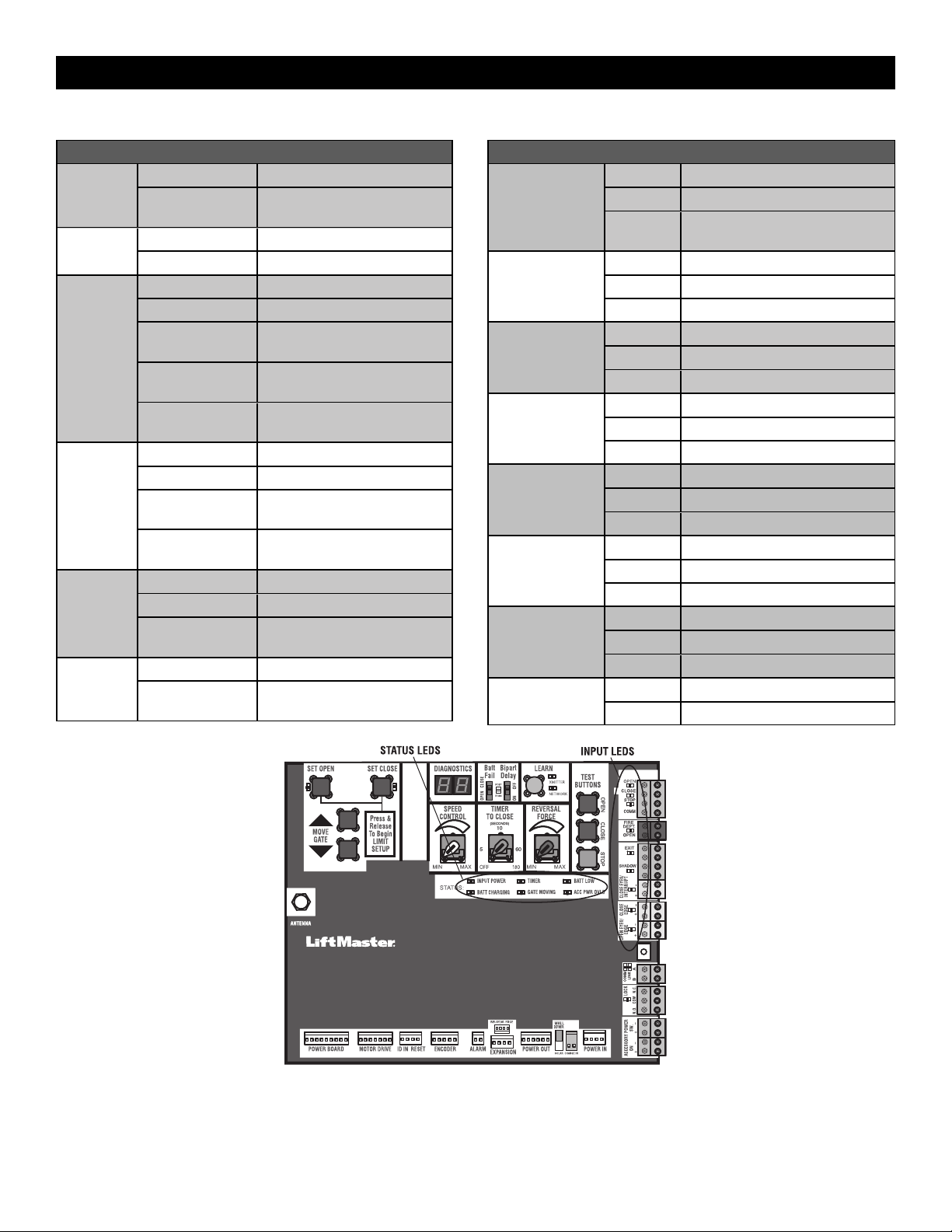
43
Control Board LEDs
STATUS LEDS
INPUT
POWER
OFF OFF state
ON AC charger or Solar power
available
BATT
CHARGING
OFF Not charging
ON Three stage battery charging
TIMER
OFF The timer is disabled
ON The timer is enabled
MEDIUM BLINK (1
blink per second)
The timer is running
FAST BLINK (2
blinks per second)
The timer is paused
FASTEST BLINK (8
blinks per second)
The timer is canceled
GATE
MOVING
OFF The gate is stopped
ON The gate is opening or closing
MEDIUM BLINK (1
blink per second)
Operator is in E1 (single
entrapment)
FASTEST BLINK (8
blinks per second)
The operator is in E2 (double
entrapment)
BATT LOW
OFF No battery error
ON Battery low
MEDIUM BLINK (1
blink per second)
Battery critically low
ACC PWR
OVLD
OFF Accessory power is okay
ON Accessory overload protector
opened
INPUT LEDS
OPEN, CLOSE,
STOP INPUT
OFF Input inactive
ON Input active
BLINK Input active on other operator or
expansion board
FIRE DEPT INPUT
OFF Input inactive
ON Input active
BLINK Input active on other operator
EXIT
OFF Input inactive
ON Input active
BLINK Input active on other operator
SHADOW
OFF Input inactive
ON Input active
BLINK Input active on other operator
CLOSE
EYES/INTERRUPT
OFF Input inactive
ON Input active
BLINK Input active on other operator
CLOSE EDGE
OFF Input inactive
ON Input active
BLINK Input active on other operator
OPEN EYES/EDGE
OFF Input inactive
ON Input active
BLINK Input active on other operator
LOCK
OFF Maglock relay inactive
ON Maglock relay active
TROUBLESHOOTING

44
Troubleshooting Chart
SYMPTOM POSSIBLE CAUSES SOLUTIONS
Operator does not
run and diagnostic
display not on.
a. No power to control board
b. Open fuse
c. If on battery power only, low or dead
batteries
d. Inoperable control board
e. Inoperable power board
a. Check AC and battery power
b. Check fuses on the power board
c. Charge batteries by AC or solar power or replace batteries
d. Replace inoperable control board
e. Replace power board
Control board
powers up, but
motor does not
run.
a. Reset switch is in the RESET position
b. Jumper is not in place for stop circuit
c. If on battery power only, low or dead
batteries
d. Open or close input active
e. Entrapment protection device active
f. Vehicle loop detector or probe active
g. Inoperable control board
h. Inoperable motor or motor control module
a. Set reset switch to NORMAL OPERATION
b. Put a jumper on the stop circuit
c. Charges batteries by AC or solar power or replace batteries
d. Check all open and close inputs for a “stuck on” input
e. Check all entrapment protection device inputs for a “stuck on” sensor
f. Check all vehicle detector inputs for a “stuck on” detector
g. Replace inoperable control board
h. Replace motor or motor control module
Gate moves, but
cannot set correct
limits.
a. Gate does not move to a limit position
b. Gate is too difficult to move
d. Limits are set too close
a. Use manual disconnect, manually move gate, and ensure gate moves
easily limit to limit. Repair gate as needed.
b. Gate must move easily and freely through its entire range, limit to limit.
Repair gate as needed.
d. Change geometry or allow gate to open further
Gate does not fully
open or fully close
when setting
limits.
a. Gate does not move to a limit position
b. Gate is too difficult to move
a. Use manual disconnect, manually move gate, and ensure gate moves
easily limit to limit. Repair gate as needed.
b. Gate must move easily and freely through its entire range, limit to limit.
Repair gate as needed.
Operator does not
respond to a wired
control/command
(example: open,
close, SBC, etc.)
a. Check open and close command input
LEDs
b. Reset switch is in the RESET position
c. If on battery power only, low or dead
batteries
d. Entrapment protection device active
e. Vehicle loop detector or vehicle probe
active
a. Check all open and close inputs for a “stuck on” input
c. Set reset switch to NORMAL OPERATION, see page 33
d. Charges batteries by AC or solar power or replace batteries
e. Check all entrapment protection device inputs for a “stuck on” sensor
f. Check all vehicle detector inputs for a “stuck on” detector
Operator does not
respond to a
wireless control or
transmitter
a. Check XMITTER LED when wireless
control is active
b. Reset switch is in the off position
c. Poor radio reception
a. Activate wireless control and check XMITTER LED is on. Re-learn
wireless control/transmitter to control board. Replace wireless control as
needed.
c. Set reset switch to NORMAL OPERATION, see page 33
d. Check if similar wired control operates correctly. Check if wireless
controls works properly when within a few feet of operator. Check
operator’s antenna and antenna wire. Check other wireless controls or
devices.
Gate stops during
travel and reverses
immediately.
a. Control (open, close) becoming active
b. Vehicle loop detector active
c. Low battery voltage
d. Inherent entrapment protection was
activated while moving
a. Check all open and close inputs for an active input
b. Check all vehicle detector inputs for an active detector
c. Battery voltage must be 23 Vdc or higher. Charge batteries by AC or
solar power or replace batteries
d. If there are no obstructions in gate path, manually disconnect the gate,
and ensure it moves easily limit to limit. Repair gate as needed.
TROUBLESHOOTING

45
SYMPTOM POSSIBLE CAUSES SOLUTIONS
Gate opens, but
will not close with
transmitter or
Timer-to-Close.
a. Open control active
b. Vehicle loop detector active
c. Loss of AC power with AC FAIL set to
OPEN
d. Low battery with LOW BATT set to OPEN
e. Fire dept input active
f. Timer-to-Close not set
g. Close entrapment protection device active
a. Check all open inputs for an active input
b. Check all vehicle detector inputs for an active detector
c. Check AC power and AC Fail option setting
d. Check if AC power is available. If no AC power, then running on
batteries and battery voltage must be 23 Vdc or higher. Charge batteries
by AC or solar power or replace batteries.
e. Check Fire Dept input
f. Check Timer-to-Close (TTC) setting
g. Check all entrapment protection device inputs for an active sensor
Gate closes, but
will not open.
a. Vehicle loop detector active
b. Low battery with LOW BATT option set to
CLOSE
a. Check all vehicle detector inputs for an active detector
b. Check if AC power is available. If no AC power, then running on
batteries and battery voltage must be 23 Vdc or higher. Charge batteries
by AC or solar power or replace batteries.
Exit loop activation
does not cause
gate to open.
a. Exit vehicle detector setup incorrectly
b. Inoperable exit loop detector
c. Low battery with LOW BATT option set to
CLOSE
a. Review exit loop detector settings. Adjust settings as needed.
b. Replace inoperable exit loop detector.
c. Check if AC power is available. If no AC power, then running on
batteries and battery voltage must be 23 Vdc or higher. Charge batteries
by AC or solar power or replace batteries.
Interrupt loop does
not cause gate to
stop and reverse.
a. Vehicle detector setup incorrectly
b. Inoperable vehicle loop detector
c. Anti-tail set to ON
a. Review Interrupt loop detector settings. Adjust settings as needed.
b. Replace inoperable Interrupt loop detector.
c. Set anti-tail to OFF.
Shadow loop does
not keep gate at
open limit.
a. Vehicle detector setup incorrectly
b. Inoperable vehicle loop detector
a. Review shadow loop detector settings. Adjust settings as needed.
b. Replace inoperable shadow loop detector.
Obstruction in
gate's path does
not cause gate to
stop and reverse.
a. Force adjustment needed a. Refer to the Adjustment section to conduct the obstruction test and
perform the proper force adjustment that is needed.
Photoelectric
sensor does not
stop or reverse
gate.
a. Incorrect photoelectric sensor wiring
b. Inoperable photoelectric sensor
a. Check photoelectric sensor wiring. Retest that obstructing photoelectric
sensor causes moving gate to stop, and may reverse direction.
b. Replace inoperable photoelectric sensor. Retest that obstructing
photoelectric sensor causes moving gate to stop, and may reverse
direction.
Edge sensor does
not stop or reverse
gate.
a. Incorrect edge sensor wiring
b. Inoperable edge sensor
a. Check edge sensor wiring. Retest that activating edge sensor causes
moving gate to stop and reverse direction.
b. Replace inoperable edge sensor. Retest that activating edge sensor
causes moving gate to stop and reverse direction.
Alarm sounds for 5
minutes or alarm
sounds with a
command.
a. Double entrapment occurred (two
obstructions within a single activation)
a. Check for cause of entrapment (obstruction) detection and correct. Press
the reset button to shut off alarm and reset the operator.
Alarm beeps three
times with a
command.
a. Low battery a. Check if AC power is available. If no AC power, then running on
batteries and battery voltage must be 23 Vdc or higher. Charge batteries
by AC or solar power or replace batteries
On dual-gate
system, incorrect
gate opens first or
closes first.
a. Incorrect bipart switch setting a. Change setting of both operator’s bipart switch settings. One operator
should have bipart switch ON (operator that opens second) and the other
operator should have bipart switch OFF (operator that opens first).
Alarm beeps when
running.
a. Expansion board setting
b. Constant pressure to open or close is given
a. Pre-warning is set to "ON"
b. Constant pressure to open or close is given
TROUBLESHOOTING

46
SYMPTOM POSSIBLE CAUSES SOLUTIONS
Expansion board
function not
controlling gate.
a. Inoperable main board to expansion board
wiring
b. Incorrect input wiring to expansion board
c. Inoperable expansion board or inoperable
main board
a. Check main board to expansion board wiring. If required, replace wire
cable.
b. Check wiring to all inputs on expansion board.
c. Replace inoperable expansion board or main board
Maglock not
working correctly.
a. Maglock wired incorrectly a. Check that maglock is wired to N.C. and COM terminals. Check that
maglock has power (do not power maglock from control board
accessory power terminals). If shorting lock’s NO and COM wires does
not activate maglock, then replace maglock or maglock wiring (refer to
wiring diagram).
Solenoid lock not
working correctly.
a. Solenoid wired incorrectly a. Check that solenoid is wired to N.O. and COM terminals. Check that
solenoid has power (do not power solenoid from control board
accessory power terminals). If shorting lock’s NC and COM wires does
not activate solenoid, then replace solenoid lock or solenoid wiring
(refer to wiring diagram).
Switched (SW)
accessory power
remaining on.
a. In limit setup mode a. Learn the limits
Accessories
connected to
switched (SW)
accessory power
not working
correctly, turning
off, or resetting.
a. Normal behavior a. Move accessory to accessory power "ON"
Accessories
connected to
Accessory power
not working
correctly, turning
off, or resetting.
a. Accessory power protector active
b. Inoperable control board
a. Disconnect all accessory powered devices and measure accessory power
voltage (should be 23 – 30 Vdc). If voltage is correct, connect
accessories one at a time, measuring accessory voltage after every new
connection.
b. Replace inoperable control board
Quick close not
working correctly.
a. Quick close setting incorrect
b. Interrupt loop detector
c. Inoperable expansion board
a. Check that quick close setting is ON
b. Check operation of interrupt loop detector
c. Replace inoperable expansion board
Anti-tailgating not
working correctly.
a. Anti-tail setting incorrect
b. Interrupt loop detector
c. Inoperable expansion board
a. Check that anti-tail setting is ON
b. Check operation of Interrupt loop detector
c. Replace inoperable expansion board
AUX relay not
working correctly.
a. AUX relay setting incorrect
b. AUX relay wiring incorrect
c. Inoperable expansion board or relay board
a. Check AUX relay switches settings
b. Check that wiring is connected to either N.O. and COM or to N.C. and
COM.
c. Set AUX relay to another setting and test. Replace inoperable expansion
board or relay board.
Solar operator not
getting enough
cycles per day.
a. Insufficient panel wattage
b. Excessive accessory power draw
c. Old batteries
d. Solar panels are not getting enough
sunlight
a. Add more solar panels
b. Reduce the accessory power draw by using LiftMaster low power
accessories
c. Replace batteries
d. Relocate the solar panels away from obstructions (trees, buildings, etc.)
Solar operator,
insufficient standby
time.
a. Insufficient panel wattage
b. Excessive accessory power draw
c. Battery capacity too low
a. Add more solar panels
b. Reduce the accessory power draw by using LiftMaster low power
accessories
c. Use batteries with higher amp hour (AH) rating
TROUBLESHOOTING
47
Step 8 Solar Panel(s)
SOLAR PANELS ARE NOT PROVIDED. SEE ACCESSORIES
NOTE: The use of photoelectric sensor heaters (models LMRRUL and LMTBUL) is NOT recommended in solar applications.
Solar Application Requirements
• A minimum of two 10W solar panels in series (Model SP10W12V).
• A maximum of six 10W solar panels (Model SP10W12V).
• A heater cannot be used with a solar application.
Solar Zones
Solar panel recommendations are based upon the average solar radiation
and the temperature effects on batteries in the given zones as shown on the
map below. Local geography and weather conditions may require
additional solar panels. Solar powered gate operator installations are not
supported in northern climates due to cold weather and a reduced number
of hours of sunlight during the winter months. The cycles/day ratings are
approximations. Ratings vary based on gate construction, installation, and
temperature. Solar panels cannot be installed in areas that experience long
periods of heavy fog, lake effect snow, or rain.
ZONE 1 (6 Hours of Sunlight/Day): Ideal for
solar application
ZONE 2 (4 Hours of Sunlight/Day):
Recommended for solar application
ZONE 3 (2 Hours of Sunlight/Day): Success
of solar application will depend on type of
gate operator and location of the solar panel
NOT AVAILABLE
1
2
3
3
2
1
1
NOT AVAILABLE
SOLAR PANELS
48
Solar usage guide
All performance metrics are estimates and are subject to change at any time. Actual results will vary due to variables specific to the site.
Typical System Standby Battery Current Consumption (mA)
System voltage 24V
Main board with no radios programmed 2.7 mA
One or more LiftMaster
®
remote controls programmed +1 mA
myQ
®
device or wireless dual gate programmed +2.4 mA
Expansion board +11.1 mA
Relay adapter board +11.1 mA
Per loop detector LOOPDETLM (up to 3 loop detectors can be plugged in to the expansion board) +3.8 mA
Add up current draw by feature and accessory to determine total current draw
NOTE: The use of photoelectric sensor heaters (models LMRRUL and LMTBUL) is NOT recommended in solar applications.
SOLAR GATE CYCLES PER DAY - 22 ft. 2,500 lb. gate
BATTERY CURRENT
DRAW (mA)
ZONE 1 ZONE 2 ZONE 3
7AH batteries 33AH batteries 7AH batteries 33AH batteries 7AH batteries 33AH batteries
20W SOLAR PANEL
5 14 16
15 12 15
20 12 14
50 11
100
40W SOLAR PANEL
5 25 36 15 22
15 24 35 14 20
20 24 34 34 20
100 14 23 10
200 11
60W SOLAR PANEL
5 32 57 19 34 14
15 30 55 18 33 13
20 30 54 17 32 13
100 19 43 22
250 22
SOLAR PANELS
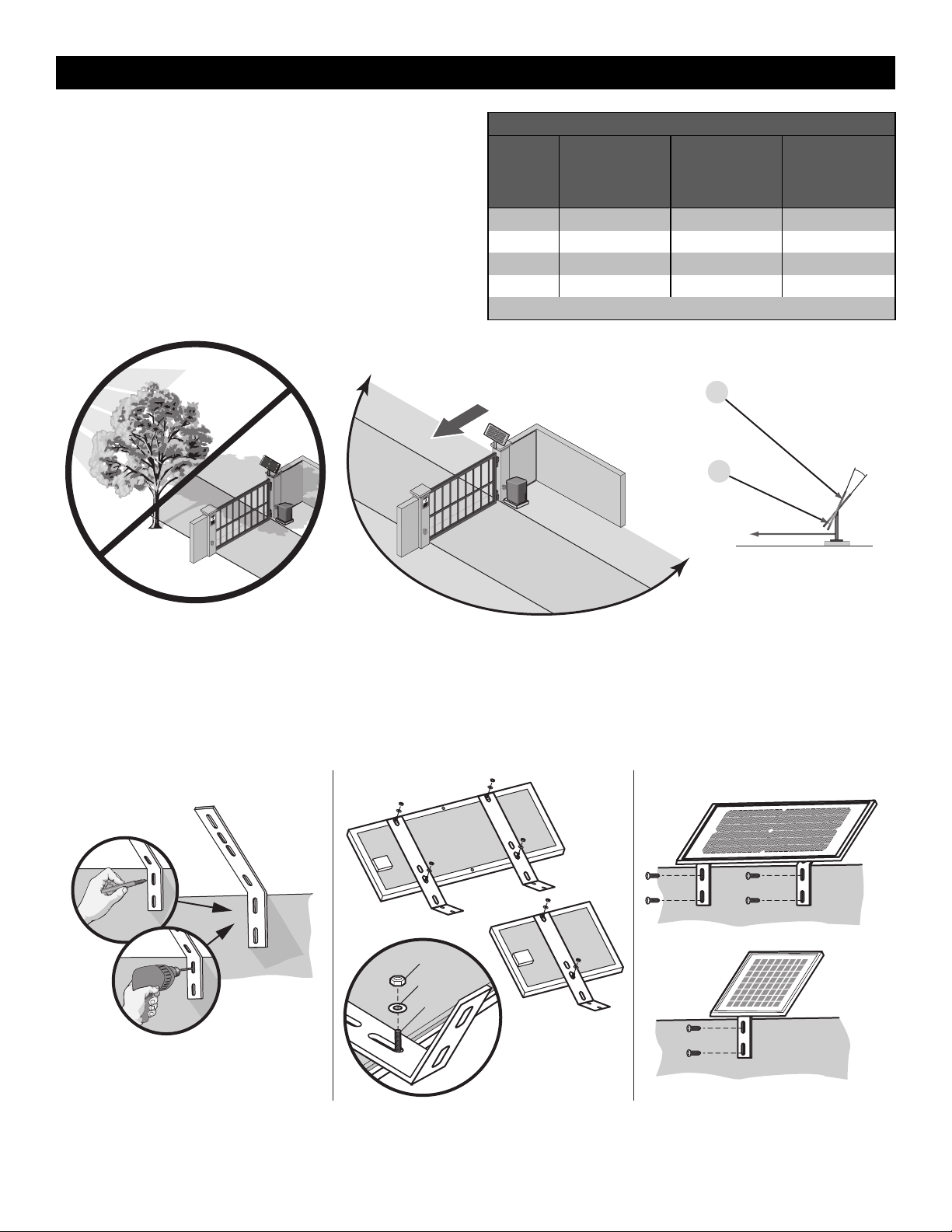
49
Position
The location of the panel(s) is critical to the success of the installation. In
general, the panel(s) should be mounted using the provided angle bracket
facing due south. The solar panel(s) should be mounted in an area clear of
all obstructions and shade from buildings and trees. If the panel(s) is not
casting a shadow, the battery is not being charged.
NOTE: Tall trees or buildings that do not shade the solar panel(s) in the
summer could shade the solar panel(s) during the winter months when the
sun sits lower in the sky.
MAXIMUM WIRE LENGTH
AMERICAN
WIRE
GAUGE
(AWG)
20 WATTS OF
PANELS
40 WATTS OF
PANELS
60 WATTS OF
PANELS
16 235 (71.6 m) 115 (35.1 m) 80 (24.4 m)
14 375 (114.3 m) 190 (57.9 m) 125 (38.1 m)
12 600 (182.9 m) 300 (91.4 m) 200 (61 m)
10 940 (286.5 m) 475 (144.8 m) 315 (96 m)
Chart assumes: copper wire, 65°C, 5% drop, 30V nominal
TIP: The area around the solar panel(s)
should be clear of shadows or obstructions
to the sun for a 180° arc east to west.
Sun’s position
Summer Sun Height
Winter Sun Height
Up to 15°
South
South
180°
TIP: To optimize the system for winter
operation the angle can be increased an
additional 15° (solar panel(s) sits more
vertical).
Installation
Solar panel(s) MUST be installed facing south. Use a compass to determine direction. Below are general instructions for installing the solar panel(s). Your
installation may vary slightly depending on the solar panel purchased.
1. Position the mounting bracket on the mounting surface. Mark and drill holes.
2. Secure the solar panel to the mounting bracket using the hex bolts, hex nuts and washers provided.
3. Secure the solar panel to the mounting surface using lag screws provided.
Hex Nut
Washer
Hex Bolt
Mounted panel must face SOUTH
1 2 3
Mounting
Surface
Mounting
Surface
SOLAR PANELS
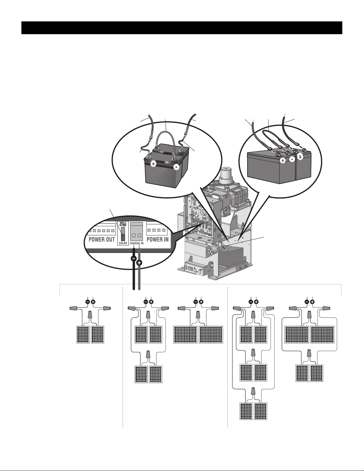
50
Wire the Solar Panels and Batteries
24W min. - 60Wmax. for solar applications.
NOTE: 33AH batteries are strongly recommended for optimal solar
performance.
1. Connect (+) wire from solar panels to (+) pin on CHARGE IN
connector on control board.
2. Connect (-) wire from solar panels to (-) pin on CHARGE IN
connector on Control board.
3. Set the WALL XFMR/SOLAR switch to SOLAR.
10W 10W
10W 10W
40W APPLICATION IN SERIES
10W 10W
10W 10W
20W 20W
60W APPLICATION IN SERIES
10W 10W
10W 10W
10W 10W
20W 20W
Red Wire
Black Wire
Black Wire
Jumper
7AH Batteries
20W APPLICATION IN SERIES
Battery Wiring
Set Switch to SOLAR
Control Board
33AH Batteries
Red Wire
Jumper
Black wire
from battery
harness 33AH,
HD Gates
K41-0102-000
Red wire from
battery harness
33AH, HD Gates
K41-0102-000
SOLAR PANELS

51
Antenna
Assembly
76-36391
Lock and Keys
K75-36260
NOT SHOWN
K41-0047-000 Wire harnesses - control board to
power board, control board to
ground, control board to transformer,
and power board to transformer)
K94-34778 Wire harness - control board to
expansion board
K41-0097-000 Motor, motor drive, and power board
K41-0102-000 33AH battery harness
40-39235 Warning sign
Control Board Pivot
Bracket and Slide Lock
K41-0074-000
Expansion Board
K1D8387-1CC
APS encoder with cable
K41-0092-000
EMI Assembly Complete
K41-0078-000
EMI Board
K1D7078
Cover with Labels,
Lock, and Keys
K41-0090-000
Gear Reducer
K41-0066-000
Relay Adapter Board
K41-0072-000
Top (Cludge) Cover
K13-36117-1
Bridge Rectifier
K41-0083-000
HD Power Board
K41-0071-000
Control Board
K41-0094-000
Dust Guard
K41-0075-000
Standard Arm Assembly
K41-0138-000
7AH 12 Vdc Batteries
K74-30762 (2)
29-NP712 (1)
Output Arm
K09-50119
Cludge Assembly
K41-0085-000
Output Shaft Complete
K41-0086-000
Motor Drive
K41-0095-000
Motor
K41-0082-000
Transformer
K41-0067-000
REPAIR PARTS
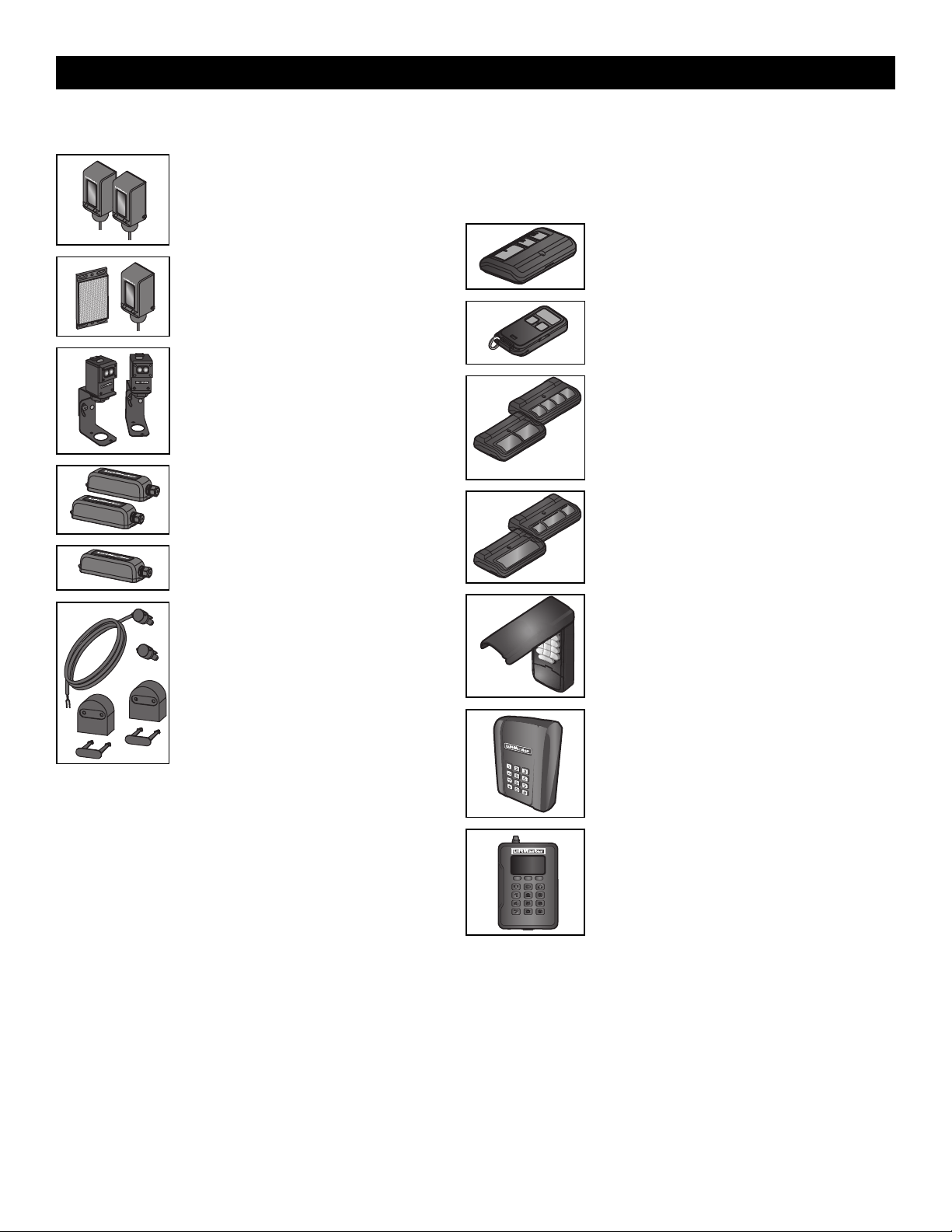
52
Entrapment Protection
LiftMaster monitored through beam photoelectric
sensor
Models LMTBUL and LMTBU
LiftMaster monitored retro-reflective photoelectric
sensor
Models LMRRUL and LMRRU
LiftMaster Monitered Commercial Protector
System
®
Models CPS-UN4 and CPSUN4G
LiftMaster monitored wireless edge kit (transmitter
and receiver)
Model LMWEKITU
LiftMaster monitored wireless edge transmitter
Model LMWETXU
Large profile monitored edge (82 ft. roll)
Model L50
Large profile ends kit (10 pair)
Model L50E
Small profile monitored edge (82 ft. roll)
Model S50
Small profile ends kit (10 pair)
Model S50E
Plastic channel
8 ft. (2.4 m) for both small and large profile edges (pack of 10).
Model L50CHP
Aluminum channel
10 ft. (3.1 m) for both small and large edge profiles (pack of 8).
Model L50CHAL
LiftMaster large profile monitored edges (4ft.,5ft., 6ft.)
Model L504AL, L505AL, L506AL
Remote Controls
LiftMaster offers a variety of LiftMaster remote controls to satisfy your application
needs. Single-button to 4-button, visor or key chain. The following remote controls are
compatible with operators manufactured by LiftMaster after 1993. Contact your
authorized LiftMaster dealer for additional details and options.
3-button remote control
The 3-button remote control can be programmed to control
the operator. Includes visor clip.
Model 893MAX
3-button mini-remote control
The 3-button remote control can be programmed to control
the operator. Includes key ring and fastening strip.
Model 890MAX
Security+ 2.0
®
learning remote controls
One button can control a gate operator and the other(s)
can control garage door(s). It can also be programmed to
Security+
®
or Security+ 2.0
®
code format.
Models 892LT and 894LT
Universal single and 3-button remote controls
Ideal for applications requiring a large number of remote
controls.
Models 811LM and 813LM
Keyless entry
Enables homeowner to operate gate operator from outside
by entering a 4-digit code on a specially designed keypad.
Model 877MAX
Wireless commercial keypad
Durable wireless keypad with blue LED backlight metal
keypad, zinc-alloy metal front cover and 5 year 9V lithium
battery. Security+ 2.0
®
compatible.
Model KPW250
Commercial access control receiver
Access control receiver for up to 1,000 devices (any
combination of remote controls and wireless keyless
entries).
Model STAR1000
ACCESSORIES
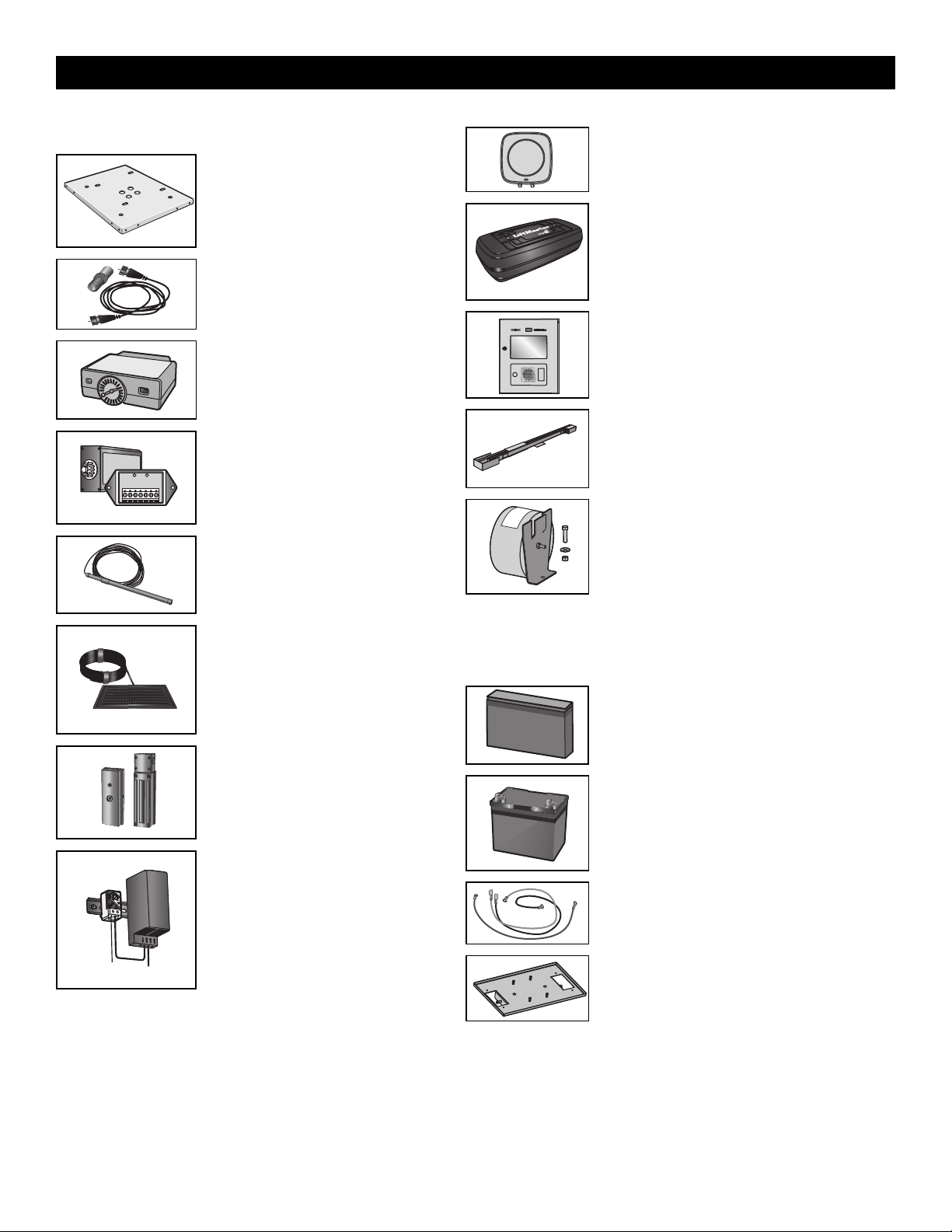
53
Miscellaneous
Post-mounting plate
For post-mounting models CSL24UL, CSW24UL,
CSW200UL, SL3000UL, HDSL24UL,
HDFSL24UL, and HDSW24UL commercial gate
operators. Posts not included.
Model MPEL
Remote antenna extension kit
The remote antenna extension kit allows the
antenna to be remotely installed.
Model 86LM
Plug-in loop detector
Low power. Conveniently plugs into existing
control board. Not to be used as entrapment
protection.
Model LOOPDETLM
Loop Detector
Low power loop detectors mounted and wired
separately inside control box. LiftMaster low
power accessory. Not to be used as entrapment
protection.
Model LD7LP
Vehicle sensing probe
The vehicle sensing probe is buried in the ground
and can detect a car as it approaches and will
then open the gate.
Model CP3
Solar panel kit
This kit is to replace or add a solar panel to the
operator application. 60W maximum for 24 Vdc
operators and 30W maximum for 12 Vdc
operators.
Models SP10W12V (10 Watt, 12V) and
SP20W12V (20 Watt, 12V)
Magnetic gate lock
Outdoor magnetic lock, transformer, junction
box, mounting plate and hardware. Not for use
with Solar Applications. Must be powered
separately.
Model MG1300
Heater
The heater keeps the gearbox and batteries at a
suitable temperature when the outside
temperature is below -4°F (-20°C). The
thermostat MUST be set between 45°F and 60°F
(7°C and 15.5°C) to ensure proper gate
operation. The heater can be powered by 110 to
250 Vac.
Model HTR
Solenoid lock harness kit
Model K77-37972
Warning sign
Model 40-39235
Long range RFID reader
Model LMSC1000
LiftMaster
®
Internet Gateway
Internet enabled accessory which connects your gate
operator to your WiFi network and allows you to monitor
and control gate operators and lighting accessories
enabled by myQ
®
technology.
Model 828LM
myQ
®
Business™ connected access protocol - high
capacity
Modesl CAPXL and CAPXLV
Long arm kit
To optimize performance and extend operator life, the long
arm kit model HDLGARM is recommended when installing
with gates 16 ft. or longer.
Model HDLGARM
Transformer kit
Changes input voltage (208/240/480/575 Vac) to an output
voltage of 120 Vac. Rated 208/240/480/575 Vac,
5.2/4.5/2.3/1.9 A, 60 Hz, 1 PH
Model 3PHCONV
Transformer kit is NOT compatible with 33AH batteries.
Batteries
Gate access system batteries replace or upgrade the gate operator batteries. Two
identical 12 Vdc batteries are required for each gate operator. Do not mix 7AH and 33AH
batteries within a gate operator.
7AH batteries
Standard 7 AMP-Hour Battery, 12 Vdc, to replace original
batteries provided with operator. Reuse existing
harnesses.
Models 29-NP712 (1) and K74-30762 (2)
33AH batteries
Upgrade 33 AMP-Hour Battery, 12 Vdc. Ideal for solar
applications and extended battery backup. Two required.
Model A12330SGLPK
33AH batteries are NOT compatible if transformer kit
model 3PHCONV is installed.
Battery harness, 33AH, HD Gates
For 33AH battery applications.
Model K41-0102-000
33AH battery tray, HD
For 33AH battery applications.
Model K41-0105-000
ACCESSORIES

54
LiftMaster 7 year residential / 5 year commercial Limited Warranty
LiftMaster (“Seller”) warrants to the first purchaser of this product, for the structure in which this product is originally installed, that it is free from defect in
materials and/or workmanship for a period of 7 year residential installation / 5 year commercial installation from the date of purchase [and that the
HDSW24UL is free from defect in materials and/or workmanship for a period of 7 year residential installation / 5 year commercial installation from the date
of purchase]. The proper operation of this product is dependent on your compliance with the instructions regarding installation, operation, maintenance
and testing. Failure to comply strictly with those instructions will void this limited warranty in its entirety.
If, during the limited warranty period, this product appears to contain a defect covered by this limited warranty, call 1-800-528-2806, toll free, before
dismantling this product. Then send this product, pre-paid and insured, to our service center for warranty repair. You will be advised of shipping
instructions when you call. Please include a brief description of the problem and a dated proof-of-purchase receipt with any product returned for warranty
repair. Products returned to Seller for warranty repair, which upon receipt by Seller are confirmed to be defective and covered by this limited warranty, will
be repaired or replaced (at Seller’s sole option) at no cost to you and returned pre-paid. Parts will be repaired or replaced with new or factory-rebuilt parts
at Seller’s sole option.
ALL IMPLIED WARRANTIES FOR THE PRODUCT, INCLUDING BUT NOT LIMITED TO ANY IMPLIED WARRANTIES OF MERCHANTABILITY AND FITNESS
FOR A PARTICULAR PURPOSE, ARE LIMITED IN DURATION TO THE 7 YEAR RESIDENTIAL / 5 YEAR COMMERCIAL LIMITED WARRANTY PERIOD SET
FORTH ABOVE [EXCEPT THE IMPLIED WARRANTIES WITH RESPECT TO THE HDSW24UL, WHICH ARE LIMITED IN DURATION TO THE 7 YEAR
RESIDENTIAL / 5 YEAR COMMERCIAL LIMITED WARRANTY PERIOD FOR THE HDSW24UL, AND NO IMPLIED WARRANTIES WILL EXIST OR APPLY
AFTER SUCH PERIOD. Some states do not allow limitations on how long an implied warranty lasts, so the above limitation may not apply to you. THIS
LIMITED WARRANTY DOES NOT COVER DAMAGE CAUSED BY IMPROPER INSTALLATION, OPERATION OR CARE (INCLUDING, BUT NOT LIMITED TO
ABUSE, MISUSE, FAILURE TO PROVIDE REASONABLE AND NECESSARY MAINTENANCE, UNAUTHORIZED REPAIRS OR ANY ALTERATIONS TO THIS
PRODUCT), LABOR CHARGES FOR REINSTALLING A REPAIRED OR REPLACED UNIT, OR REPLACEMENT OF BATTERIES.
THIS LIMITED WARRANTY DOES NOT COVER ANY PROBLEMS WITH, OR RELATING TO, THE GATE OR GATE HARDWARE, INCLUDING BUT NOT
LIMITED TO THE GATE SPRINGS, GATE ROLLERS, GATE ALIGNMENT OR HINGES. THIS LIMITED WARRANTY ALSO DOES NOT COVER ANY
PROBLEMS CAUSED BY INTERFERENCE. ANY SERVICE CALL THAT DETERMINES THE PROBLEM HAS BEEN CAUSED BY ANY OF THESE ITEMS
COULD RESULT IN A FEE TO YOU.
UNDER NO CIRCUMSTANCES SHALL SELLER BE LIABLE FOR CONSEQUENTIAL, INCIDENTAL OR SPECIAL DAMAGES ARISING IN CONNECTION WITH
USE, OR INABILITY TO USE, THIS PRODUCT. IN NO EVENT SHALL SELLER’S LIABILITY FOR BREACH OF WARRANTY, BREACH OF CONTRACT,
NEGLIGENCE OR STRICT LIABILITY EXCEED THE COST OF THE PRODUCT COVERED HEREBY. NO PERSON IS AUTHORIZED TO ASSUME FOR US ANY
OTHER LIABILITY IN CONNECTION WITH THE SALE OF THIS PRODUCT.
Some states do not allow the exclusion or limitation of consequential, incidental or special damages, so the above limitation or exclusion may not apply to
you. This limited warranty gives you specific legal rights, and you may also have other rights which vary from state to state.
WARRANTY
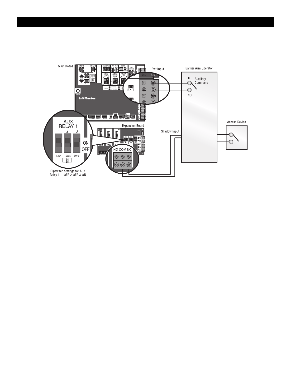
55
SAMS Wiring with Relays Not Energized
SAMS Operation
To keep vehicles from rushing the gate, the barrier arm stays in closed position until the gate reaches fully open position then the barrier arm is released to
open and allow vehicles to pass.
AUX Relay 1
APPENDIX
56
Dual Gate Settings
NOTE: We recommend that all accessories and board configurations are set on the primary operator.
Main control board
FEATURE PRIMARY OPERATOR SECONDARY OPERATOR
Timer-to-
Close
Set the TTC dial to desired
setting
OFF
Bi-Part
Delay
Switch
Synchronized Close: ON Synchronized Close: ON
Speed Set the speed control dial on each operator to the desired
setting, see page 26 for more details
Expansion board
FEATURE PRIMARY OPERATOR
SECONDARY
OPERATOR
QUICK CLOSE Switch ON OFF
ANTI-TAIL Switch ON OFF
LOW BATT Switch Battery Fail OPEN:
OPEN
Battery Fail CLOSE:
CLOSE
Battery Fail OPEN:
OPEN
Battery Fail CLOSE:
CLOSE
AC FAIL OPEN/BATT
Switch
OPEN OPEN
Accessories
ACCESSORY PRIMARY OPERATOR
SECONDARY
OPERATOR
Remote Controls Program remote
controls 1 to 50 to the
primary operator.
Program remote
controls 51 to 100 to the
secondary operator
LiftMaster Internet
Gateway
Program to primary
operator.
Garage and Gate
Monitor
Program to primary
operator.
APPENDIX
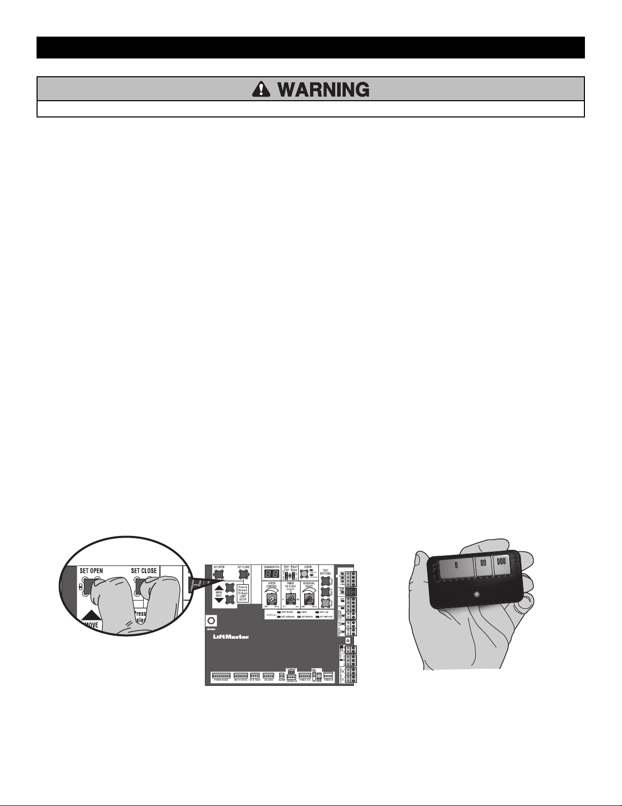
57
To reduce the risk of INJURY keep clear of moving arm while setting limits.
Limit Setup with a Remote Control
To set the limits using a remote control, first you will need a 3-button remote control that has been programmed for OPEN, CLOSE, and STOP. Refer to the
Programming section.
Initial Limits and Force Adjustment
For dual gate applications the limits will have to be set for each
operator. The gate MUST be attached to the operator before setting
the limits and force.
Ensure the gate is closed.
1. Press and release the SET OPEN and SET CLOSE buttons
simultaneously to enter limit setting mode.
2. Press and hold the OPEN or CLOSE button on the remote control
until the gate reaches the desired open position. The gate can be
jogged back and forth using the OPEN and CLOSE buttons on the
remote control.
3. Once the gate is in the desired open position, press and release the
STOP button on the remote control.
4. Press and release the OPEN button on the remote control again to
set the open limit.
5. Press and hold the CLOSE or OPEN button on the remote control
until the gate reaches the desired close position. The gate can be
jogged back and forth using the OPEN and CLOSE buttons on the
remote control.
6. Once the gate is in the desired close position, press and release the
STOP button on the remote control.
7. Press and release the CLOSE button on the remote control again to
set the close limit.
8. Cycle the gate open and close. This automatically sets the force.
When limits are set properly the operator will automatically exit limit
setting mode.
Refer to the Adjustment section and follow the instructions for Speed
Control, Fine Tune the Force, and Obstruction Test.
Adjust the limits
If the limits have already been set the operator will exit the limit setting
mode after resetting each limit.
Set the Close Limit Only
1. Press and release the SET OPEN and SET CLOSE buttons
simultaneously to enter limit setting mode.
2. Press and hold the CLOSE button on the remote control until the gate
reaches the desired close position. The gate can be jogged back and
forth using the OPEN and CLOSE buttons on the remote control.
3. Once the gate is in the desired close position, press and release the
STOP button on the remote control.
4. Press and release the CLOSE button on the remote control again to set
the close limit.
When the close limit is set properly the operator will automatically exit limit
setting mode.
Set the Open Limit Only
1. Press and release the SET OPEN and SET CLOSE buttons
simultaneously to enter limit setting mode.
2. Press and hold the OPEN button on the remote control until the gate
reaches the desired open position. The gate can be jogged back and
forth using the OPEN and CLOSE buttons on the remote control.
3. Once the gate is in the desired open position, press and release the
STOP button on the remote control.
4. Press and release the OPEN button on the remote control again to set
the open limit.
When the open limit is set properly the operator will automatically exit limit
setting mode.
Perform the obstruction test after every limit, speed, and force setting
adjustment see page 27.
3-Button Remote Control programmed for OPEN, CLOSE, and STOP
APPENDIX
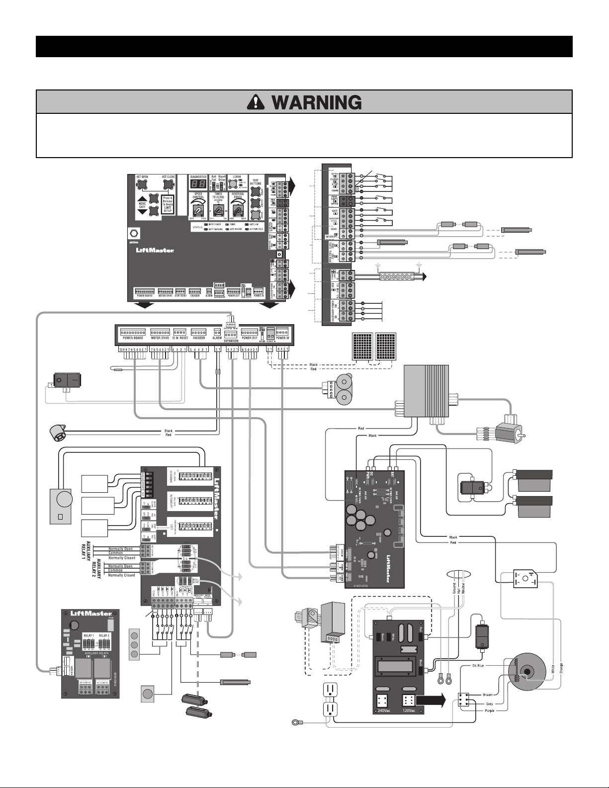
58
Wiring Diagram
To protect against fire and electrocution:
• DISCONNECT power (AC or solar and battery) BEFORE installing or
servicing operator.
For continued protection against fire:
• Replace ONLY with fuse of same type and rating.
N.C.
Jumper
PRODUCT ID
ALARM
HD POWER
BOARD
Control function
of photoelectric
sensor or edge
sensor for the
OPEN or CLOSE
cycle.
PLUG-IN
LOOP
DETECTOR
Model
LOOPDETLM
EXPANSION BOARD
N.C.
Jumper
SINGLE BUTTON
CONTROL STATION
WIRELESS
EDGE KIT
PHOTOELECTRIC SENSORS
PHOTOELECTRIC SENSORS
or EDGE SENSORS
LOCKS
ACCESSORY
POWER
DUAL
GATES
ENTRAPMENT
PROTECTION
LOOPS CONTROLS
EDGE SENSOR
for CLOSE cycle
SHADOW LOOP
EXIT LOOP
PHOTOELECTRIC SENSORS or EDGE SENSOR
for OPEN cycle
Shielded Twisted Pair Cable
(Primary/Secondary link to other gate operator) Ground the
shield of the cable to the chassis ground of each operator.
CONTROL BOARD
ANTENNA
RESET SWITCH
MOTOR
DRIVE
APS ENCODER
BLDC
MOTOR
BATTERY SWITCH
AC POWER
SWITCH
TRANSFORMER
BRIDGE RECTIFIER
29-NP712
EMI BOARD
12V SOLAR PANELS
IN SERIES
INPUT POWER
CONNECTION
12V BATTERIES
IN SERIES
RELAY ADAPTER
BOARD
SHADOW
LOOP
EXIT
LOOP
INTERRUPT
LOOP
Control
function of
Auxiliary
Relays
Attach ground wires to
metal chassis with single
PEM stud. Each ring term
needs a separate nut.
Red
Black
3-BUTTON
CONTROL STATION
OPEN and COM: Hard Open (line-of-sight)
CLOSE and COM: Hard Close (line-of-sight)
STOP and COM: Hard Stop(line-of-sight)
EXIT: Soft Open (used for exit probe, telephone
entry, external exit loop detector, or any device that
would command the gate to open)
PHOTOELECTRIC SENSORS or EDGE SENSOR
for CLOSE cycle
POWER SW - 24 VDC 1 A Maximum
ACCESSORY ON POWER - 24 VDC 1 A Maximum
APPENDIX

59
Diagnostic Codes Table
Some codes are saved in the code history and some are not. If a code is not saved it will briefly appear on the display as it occurs, then disappear.
LiftMaster System Installed System Informational
External Entrapment
Protection
Inherent Entrapment
Protection
Code Meaning Solution Saved
31
Control board has experienced an internal failure. Disconnect all power, wait 15 seconds, then reconnect power (reboot). If
issue continues, replace main control board.
NO
34
Absolute Position Encoder error, not getting
position information from encoder
Check APE assembly and wiring connections. Replace the APE assembly
if necessary.
YES
35
Max-run-time exceeded error Check for an obstruction, then reprogram the limits. YES
36
Product ID error Was the control board just replaced? If so, erase limits, enter limit setup
mode and set limits. If not, disconnect all power, wait 15 seconds, then
reconnect power before changing product ID harness.
YES
37
Product ID failure Unplug product ID harness then plug back in. Disconnect all power, wait
15 seconds, then reconnect power before replacing product ID harness.
YES
38
Hard stop limit (Arm 1) Limit may be set too tightly against a non-resilient hard stop (re-adjust
limit). Operator may be at end of travel (re-adjust mounting).
NO
40
Battery overvoltage Too much voltage on the battery. Check harness. Make sure there is NOT a
24V battery on a 12V system.
YES
41
Battery overcurrent Possible short of the battery charge harness. Check harness. Make sure
you do NOT have a 12V battery on a 24V system.
YES
42
No battery at boot up Check battery connections and installation. Replace batteries if depleted to
less than 20V on a 24V system or less than 10V on a 12V system. Make
sure there is NOT a single 12V battery on a 24V system.
YES
43
Exit loop error Failure or missing loop (SHORT or OPEN - LiftMaster Plug-in Loop
Detector only). Check loop wiring throughout connection. May be a short
in the loop, or an open connection in the loop.
YES
44
Shadow loop error
45
Interrupt loop error
46
Wireless edge battery low Replace batteries in wireless edge. YES
47
Motor Drive Fault Check motor drive connections. Disconnect all power, wait 15 seconds,
then reconnect power (reboot). If issue persists, replace motor drive.
YES
48
Hall Sensor Fault Check motor and motor drive connections. Disconnect all power, wait 15
seconds, then reconnect power (reboot). If issue persists, replace motor.
YES
53
Brownout occurred
AC/DC board supply dipped below allowable level. Review power supply
and wiring. If rebooting, ensure enough time for discharge of power to
force a fresh boot.
YES
54
Wireless second operator communication error
Check the second operator for power. If OFF, restore power and try to run
the system. If powered, deactivate the wireless feature and then re-learn
the second operator.
YES
60
Minimum number of monitored entrapment
protection devices not installed.
Review monitored entrapment protection device connections. This swing
gate operator will operate only after installation of a minimum of one
external safety device in either the open or close direction.
NO
61
CLOSE EYE/INTERRUPT held more than 3 minutes
Check wired input on main control board; check for alignment or
obstruction.
YES
62
CLOSE EDGE held more than 3 minutes
63
OPEN EYE/EDGE held more than 3 minutes
64
CLOSE EYE/INTERRUPT held more than 3 minutes
Check wired input on expansion board; check for alignment or
obstruction.
YES
65
CLOSE EYE/EDGE held more than 3 minutes
66
OPEN EYE/EDGE held more than 3 minutes
67
Wireless edge triggered more than 3 minutes Check wired input for wiring issue or obstruction. YES
APPENDIX

60
Code Meaning Solution Saved
68
Wireless edge loss of monitoring Check wireless edge inputs. YES
69
Wireless edge triggered
IF an obstruction occurred, no action required. If an obstruction did NOT
occur, check inputs and wiring.
NO
70
CLOSE EYE/INTERRUPT triggered, causing
reversal, preventing close, or resetting TTC
IF an obstruction occurred, no action required. If an obstruction did NOT
occur, check alignment, inputs, and wiring on main control board
NO
71
CLOSE EDGE triggered, causing reversal, NO
preventing close, or canceling TTC
72
OPEN EYE/EDGE triggered, causing reversal or
preventing opening
73
CLOSE EYE/INTERRUPT triggered, causing
reversal, preventing close, or resetting TTC
IF an obstruction occurred, no action required. If an obstruction did NOT
occur, check alignment, inputs, and wiring on expansion board.
NO
74
CLOSE EYE/EDGE triggered, causing reversal and
preventing close or canceling TTC
75
OPEN EYE/EDGE triggered, causing reversal or
preventing opening
80
Close input (EYE/EDGE) communication fault from
other operator
Check inputs and communication method between operators, either wired
bus or radio. Ensure operator is powered. May have to erase the wireless
communication and reprogram the two operators.
YES
81
Open input (EYE/EDGE) communication fault from
other operator
82
Close input (EYE/EDGE) communication fault
(expansion board)
Check the connections between the main board and the expansion board. YES
83
Open input (EYE/EDGE) communication fault
(expansion board)
84
Non-monitored device detected on the wireless
safety system
Non-monitored contact closure devices are not supported. Make sure
connected devices are monitored. Check edges for proper orientation and
resistive end cap connection.
YES
91
Force reversal
Check for obstruction. If no obstruction, check that the mechanical
assembly is engaged and free to move. See Limit, Speed and Force
Adjustment page 25.
YES
93
RPM / STALL reversal
Check for obstruction. If no obstruction, check the operator wiring and
that the mechanical assembly is engaged and free to move. Replace APE
assembly.
YES
95
Motor start failure
Operator attempted to run, no response from motor drive assembly. Check
connector and harness. If connected properly and still not working,
replace motor and/or motor drive.
YES
96
Power board fault
Check connections to power board. Power cycle and retry. Replace power
board if issue persists.
YES
99 Normal operation No action required YES
APPENDIX

Swing and Slide Gate Operator UL 325 and
ASTM F2200 Site Planning Safety Checklist
Name:
Address:
City/State/ZIP:
Phone:
Email:
Please Print
ASTM F2200 Standards
Gate Construction Evaluation: Gate Constructed with Safety in mind. ASTM F2200 Standards are followed
Component: Result (Circle) Comments: Figures (On Back)
All Gates
Gates have smooth bottom edges, no protrusions exceed 1/2” beyond base of gate Pass / Fail
5
All access controls at least 6 ft. from gate Pass / Fail
1,4
Barbed tape (razor wire) at least 8 ft. above grade Pass / Fail
Barbed wire at least 6 ft. above grade Pass / Fail
Separate pedestrian gate – out of reach of a moving gate – vehicular gate is
for automotive traf
fi c
only
Pass / Fail
1,4
Gate does not move on its own if disconnected from operator Pass / Fail
Gates prevented from falling over if disconnected from supporting hardware Pass / Fail
SWING
Distance from pivot point to column edge is less than 4 in. or external
entrapment protection is pr
ovided
Pass / Fail
4
Distance from open gate to wall, column, or other fi xed object is greater than
16 in. or external entrapment protection is provided
Pass / Fail
4
SLIDE
Roller covers on weight bearing exposed rollers 8 ft., or less, above grade Pass / Fail
1
Meshing installed up to 6 ft. above grade if pickets spaced equal to or
greater than 2 1/4 in. apart
Pass / Fail
3
Gap between gate and fence post less than 2 1/4 in. & gap protected with safety device Pass / Fail
2
Positive stops at both fully open and fully closed positions Pass / Fail
1
Receiver guides recessed behind receiver post for receiver guides less than 8 ft. Pass / Fail
Other: Pass / Fail
© 2019 LiftMaster All Rights Reserved
300 Windsor Drive, Oak Brook, IL 60523
LMSPCLSWSL 12/19
Please Print
First & Last Name of Dealer:
Name of Dealership:
Dealership Address (Street Address/City/State/Zip):
Dealer Signature:
Customer Signature:
First & Last Name of Installer:
Phone:
Installer Signature:
Satisfactory
Needs Repair/Replacement
Gate Safety Check —
Simple steps to quickly determine if an End User’s gate operator is safe.
UL 325 Standard
Component: Result (Circle)
Comments: Figures (On Back)
1. Gate Operator is approved to current UL 325 standards (check operator label) Pass / Fail
2. Proper gate warning signs attached to both sides of gate area Pass / Fail
1,4
3. All entrapment zones protected by 2 safety devices/obstruction tested
1,4
Close Side (circle two) Photo Eye
Reversing Edge Inherent Reverse
Pass / Fail
Open Side
(circle two) Photo Eye
Reversing Edge Inherent Reverse
Pass / Fail
Other Entrapment Zones Pass / Fail
*Entrapment Zone:
The location where a person can be caught or held in a position that increases the risk of injury
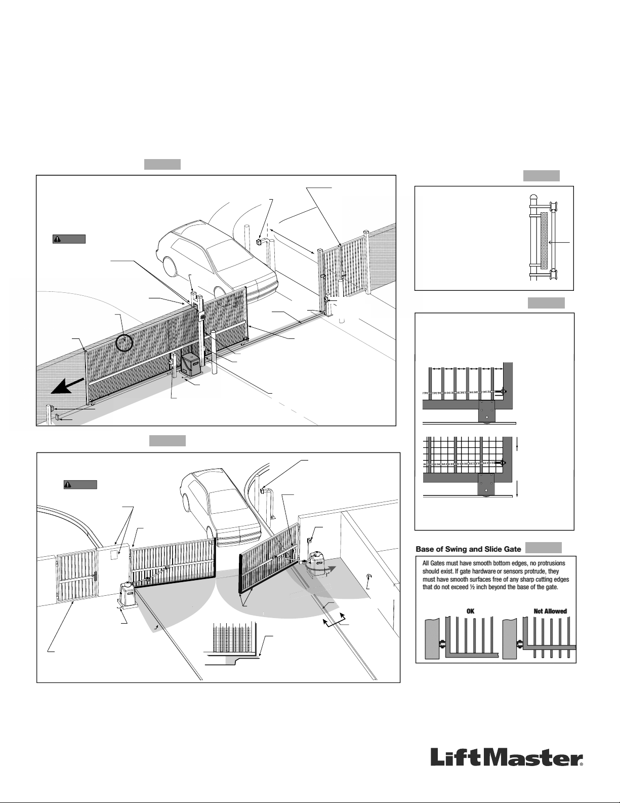
GETTING STARTED WITH SWING AND SLIDE GATE OPERATORS.
• Only install the operator on gates used for vehicular traf c.
• A separate pedestrian entry/exit must be clearly visible to promote pedestrian usage
and located so pedestrians do not come in contact with the vehicular gate while it is
moving.
• Install two independent
†
entrapment protection devices protecting each entrapment
zone.
• Pickets of a slide gate must be designed or screened to prevent persons from
reaching through, or passing through a gate.
• Every Installation is unique. It is the responsibility of the installer to ensure all
entrapment zones are protected with a minimum of two independent
†
entrapment
protection devices.
• A slide gate operator will only operate with a minimum of two independent monitored
entrapment protection devices installed in each direction, two in the open direction
and two in the closed direction
†
.
• A swing gate operator will only operate with a minimum of two independent monitored
entrapment protection devices installed in either the open or closed direction. If
no entrapment zone exists in the other direction, only one means of entrapment
protection is required in that direction
†
.
Always design, install and maintain safe gate access systems in accordance with UL 325 & ASTM F2200 standards.
SLIDE GATE SITE LAYOUT GUIDELINES
SECURE SIDE
PUBLIC SIDE
Be sure to place the
WARNING signs on both
sides of the gate in clear view.
For your records, take a photograph of the
completed installation site.
WARNING
Gap between vertical bars
must be less than 2¼" (57 mm)
Left Hand Gate
opening
Physical stop - at both ends of gate rail.
Photo eye (Emitter or Reflector in the Open direction)
Edge sensor
on Trailing Edge
of gate
Pedestrian gate located
near the slide gate.
Mount access control
devices at least 6 ft
(1.8 m) beyond the gate.
Make sure a separate walk-
through entrance is available
and its pedestrian path is
clearly designated.
Edge sensor on
Leading Edge of gate
V track
(gate rail)
Physical
stop
Earth ground
Interior posts,
Non-pinch
rollers (2x)
Guide
posts
ENTRAPMENT
NOTE: Any gap larger than 2¼" (57 mm) between
gate and fixed objects must be protected. Install
edge sensors where gap between post and gate
creates an entrapment zone.
6 ft (1.8 m) minimum
Photo eye (Receiver)
Photo eye (Receiver)
Photo eye
Emitter or Reflector
(Close direction)
ZONE
Edge sensor (Draw-in zone)
SECURE SIDE
PUBLIC SIDE
Pedestrian gate located
near the swing gate.
Make sure a separate walk-through entrance is
available and its pedestrian path is clearly designated.
Mount access control
devices at least 6 ft
(1.8 m) beyond the gate.
Photo
eyes
ZONE
Photo eye
(public side)
Edge
sensor
Earth ground
Reector
for Photo
Eye
ENTRAPMENT
Be sure to place the
WARNING signs on both
sides of the access point in clear view of vehicles.
For your records, take a photograph of the
completed installation site.
WARNING
ENTRAPMENT
Curb
Curb
A
View A
Cross Section
ENTRAPMENT
ZONE
Photo eye
(public side)
SWING GATE SITE LAYOUT GUIDELINES
Ed
ge
sensor
ENTRAP
RAPMEN
C
Gate Frame and Adjacent Fence Area
6 ft. minimum
X X XX X XX X X XXXXXX X X X
Gate Frame and Adjacent Fence Area
If gaps (xxx)
between vertical
bars of the gate or
fence are less
than 2 1/4", no
further screening
is required.
For gaps (xxx)
equal to or larger
than 2 1/4", a wire
mesh screen must
be applied to the
gate. Wire mesh
screen openings
must be smaller
than 2 1/4". The
minimum height of
wire mesh screen:
6 ft. above grade.
SLIDE GATE OPENINGS GUIDELINES
Openings of a horizontal slide gate must be smaller than 2 1/4"
or else be guarded or screened. These design rules apply to
both the moving gate as well as the portion of adjacent fence
that the gate covers in the open position. See Illustrations
below.
SLIDE GATE SPACING GUIDELINES
Slide Gate Gaps
A gap, measured in the horizontal plane
parallel to the roadway, between a fixed
stationary object nearest the roadway (such
as a gate support post) and the gate frame
when the gate is in either the fully open
position or the fully closed position, shall not
exceed 2 ¼ in.. Exception: All other fixed
stationary objects greater than 16 in. from
the gate frame shall not be required to
comply with this section. Any gap must be
protected. Install safety device to protect
entrapment zone.
**Swing Gate Entrapment Zones: Locations between a moving gate or moving, exposed operator components and a counter
opposing edge or surface where entrapment is possible up to 1.8m (6 ft) above grade. Such locations occur if during any point in travel:
a) The gap between the bottom of a moving gate and the ground is greater than 101.6mm (4 in) and less than 406mm (16 in); or
b) The distance between the center line of the pivot and the end of the wall, pillar, or column to which it is mounted when in the open
or closed position exceeds 101.6mm (4 in). Any other gap between a moving gate and xed counter opposing edges or surfaces or
other xed objects is less than 406mm (16 in) (examples are walls, curbs, berms, or other immovable objects).
Defi nitions
Entrapment: The condition when a person is caught or held in
a position that increases the risk of injury.
Slide Gate Entrapment Zones: An entrapment zone exists if
at any point during travel, the gap between the moving gate
and xed counter opposing edges or surfaces is less than
406mm (16”) in a location up to 1.8 m (6ft.) above grade.
†
Independent the same type of device shall not be utilized for both entrapment
protection devices.
FIGURE 1
The above examples are two of many installation possibilities and are for illustration purposes only.
See device and operator manuals for complete instruction.
Visit DAMSA.com for more information.
FIGURE 2
FIGURE 3
FIGURE 4
FIGURE 5

This page intentionally left blank