OWNER’S MANUAL
FOR USE ON VEHICULAR PASSAGE GATES ONLY AND NOT
INTENDED FOR USE ON PEDESTRIAN PASSAGE GATES.
INTENDED FOR PROFESSIONAL INSTALLATION ONLY.
CSW200UL
™
VEHICULAR SWING GATE OPERATOR
The Chamberlain Group, Inc.
845 Larch Avenue
Elmhurst, Illinois 60126-1196
www.liftmaster.com

1
• BEFORE attempting to install, operate or maintain the operator,
you must read and fully understand this manual and follow all
safety instructions.
• DO NOT attempt repair or service of your gate operator unless
you are an Authorized Service Technician.
When you see these Safety Symbols and Signal Words on the
following pages, they will alert you to the possibility of SERIOUS
INJURY or DEATH if you do not comply with the warnings that
accompany them. The hazard may come from something
mechanical or from electric shock. Read the warnings carefully.
When you see this Signal Word on the following pages, it will
alert you to the possibility of damage to your gate and/or the gate
operator if you do not comply with the cautionary statements that
accompany it. Read them carefully.
IMPORTANT NOTE
SPECIFICATIONS AND WARNINGS
Overview and Specifications ............................ 2
Model Classification .................................. 3
Safety Installation Information .......................... 4
Gate Construction Information .......................... 5
Suggested Entrapment Protection Device Locations ........6-7
Safety Precautions ................................... 8
INSTALLATION
Installation Setups ................................... 9
Concrete Pad and Arm Attachment...................... 10
Standard Installation Layout ........................... 11
Compact Installation Layout ........................... 12
Uphill Driveway Post Mounting Plate Installation .......... 13
Gate Arm Installation ................................ 14
Output Shaft Adjustment ............................. 14
Control Board Description ............................ 15
Surge Suppressor Terminal Connections ................. 16
WIRING
Earth Ground Rod Installation ......................... 17
110Vac Power Connection ............................ 18
Heater Power Connection ............................. 18
Linking Master/Second Operators ...................... 19
Solenoid/Maglock Connections......................... 20
DC2000 Back-Up Connections .......................21-22
Plug-In Loop Detector Wiring.......................... 23
110Vac External Loop Detector Wiring ................... 24
Entrapment Protection Devices (Edge Sensors) ............ 25
Entrapment Protection Devices (Non-Contact Sensors) ...... 26
ADJUSTMENTS
Set Gate Opening Direction............................ 27
Limit Switch Adjustments............................. 28
Clutch Adjustment .................................. 28
Radio Receiver Programming........................29-30
Setting the Timer (On, Off) ............................ 31
Adjusting Reversing Sensor(s) ......................... 32
OmniControl™ Board Connections ...................... 33
MAINTENANCE AND OPERATION
Maintenance ....................................... 34
OPERATION
Built-In Reset Switch ................................ 35
Audio Alarm ....................................... 35
EMERGENCY MANUAL RELEASE
................... 36
WIRING DIAGRAMS AND SPEC TABLES
.........37-42
TROUBLESHOOTING
...........................43-44
REPAIR PARTS
................................45-46
ACCESSORIES
................................... 47
INSTALLATION CHECKLIST
....................... 51
WARRANTY POLICY
.............................. 52
TABLE OF CONTENTS
Mechanical
Electrical
2
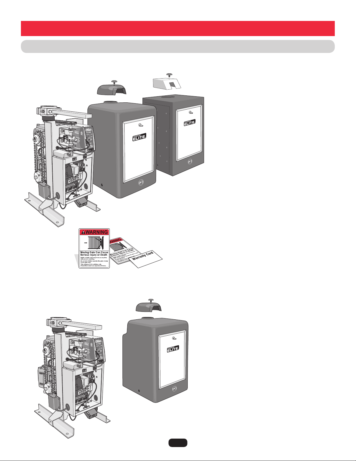
CSW200UL™ MODELS OVERVIEW
Single Motor
Cover
Twin Motor Cover
Stainless
Steel Cover
Second
Motor
Heater
Heater
DC2000™ Back-Up
Dual Motor Only.
DC2000™
Back-Up
All operators come with
2 warning placards and a
warranty card.
CSW200UL™ (Single Motor)
1/2 HP Motor, 120Vac, 4 Amp.
Maximum Gate Length – 20 ft. Maximum Gate Weight – 600 lbs.
Maximum Pull – 125 lbs.
CSW200ULDC™ (Single Motor)
1/2 HP Motor, DC2000™, 120Vac, 4 Amp.
Maximum Gate Length – 20 ft. Maximum Gate Weight – 600 lbs.
Maximum Pull – 125 lbs.
CSW200ULH™ (Single Motor)
1/2 HP Motor, 120Vac, 4 Amp., Heater 3 Amp
Maximum Gate Length – 20 ft. Maximum Gate Weight – 600 lbs.
Maximum Pull – 125 lbs.
CSW200ULDCH™ (Single Motor)
1/2 HP Motor, DC2000™, 120Vac, 4 Amp., Heater 3 Amp
Maximum Gate Length – 20 ft. Maximum Gate Weight – 600 lbs.
Maximum Pull – 125 lbs.
CSW200ULST™ (Stainless Steel Cover)
1/2 HP Motor, 120Vac, 4 Amp.
Maximum Gate Length – 20 ft. Maximum Gate Weight – 600 lbs.
Maximum Pull – 125 lbs.
CSW200ULSTDC™ (Stainless Steel Cover)
1/2 HP Motor, DC2000™, 120Vac, 4 Amp.
Maximum Gate Length – 20 ft. Maximum Gate Weight – 600 lbs.
Maximum Pull – 125 lbs.
CSW200ULSTH™ (Stainless Steel Cover)
1/2 HP Motor, 120Vac, 4 Amp., Heater 3 Amp
Maximum Gate Length – 20 ft. Maximum Gate Weight – 600 lbs.
Maximum Pull – 125 lbs.
CSW200ULSTDCH™ (Stainless Steel Cover)
1/2 HP Motor, DC2000™, 120Vac, 4 Amp., Heater 3 Amp
Maximum Gate Length – 20 ft. Maximum Gate Weight – 600 lbs.
Maximum Pull – 125 lbs.
Specifications and Warnings
Dual Motor and 1 HP Models
Single Motor and Stainless Models
NOTE: The 1 HP models Can Not have
the DC2000™ Battery Backup system.
CSW200ULDM™ (Dual Motor)
Two-1/2 HP Motors, 120Vac, 4 Amp.
Maximum Gate Length – 20 ft. Maximum Gate Weight – 800 lbs.
Maximum Pull – 115 lbs.
CSW200ULDMDC™ (Dual Motor)
Two-1/2 HP Motors, DC2000™, 120Vac, 4 Amp.
Maximum Gate Length – 20 ft. Maximum Gate Weight – 800 lbs.
Maximum Pull – 115 lbs.
CSW200ULDMH™ (Dual Motor)
Two-1/2 HP Motors, 120Vac, 4 Amp., Heater 3 Amp
Maximum Gate Length – 20 ft. Maximum Gate Weight – 800 lbs.
Maximum Pull – 115 lbs.
CSW200ULDMDCH™ (Dual Motor)
Two-1/2 HP Motors, DC2000™, 120Vac, 4 Amp., Heater 3 Amp
Maximum Gate Length – 20 ft. Maximum Gate Weight – 800 lbs.
Maximum Pull – 115 lbs.
CSW200UL1HP™ (1 Horse Power)
Two-1/2 HP Motors, 120Vac, 7.9 Amp.
Maximum Gate Length – 22 ft. Maximum Gate Weight – 1000 lbs.
Maximum Pull – 250 lbs.
CSW200UL1HPH™ (1 Horse Power)
Two-1/2 HP Motors, 120Vac, 7.9 Amp., Heater 3 Amp
Maximum Gate Length – 22 ft. Maximum Gate Weight – 1000 lbs.
Maximum Pull – 250 lbs.
3
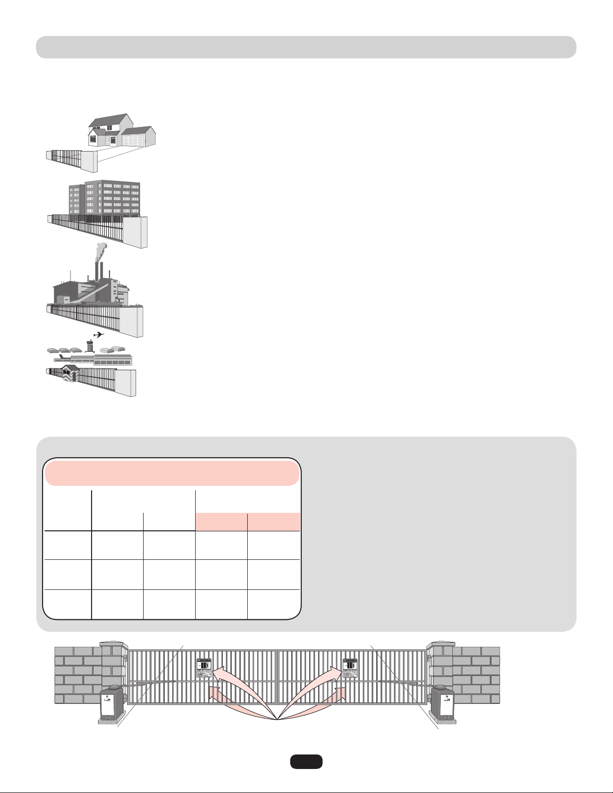
Class I – Residential vehicular gate operator
A vehicular gate operator (or system) intended for use in a home of one-to four single family
dwellings, or a garage or parking area associated therewith.
The CSW200UL™ is intended for use in vehicular swing gate applications:
40-50399A
Class II – Commercial/General access vehicular gate operator
A vehicular gate operator (or system) intended for use in a commercial location or building such as a
multi-family housing unit (five or more single family units) hotel, garage, retail store or other building
servicing the general public.
Class III – Industrial/Limited access vehicular gate operator
A vehicular gate operator (or system) intended for use in a industrial location or building such as a
factory or loading dock area or other location not intended to service the general public.
Class IV– Restricted access vehicular gate operator
A vehicular gate operator (or system) intended for use in a guarded industrial location or building such
as an airport security area or other restricted access locations not servicing the general public, in
which unauthorized access is prevented via supervision by security personnel.
UL325 MODEL CLASSIFICATIONS
NOTE: UL requires that all installations must have warning placards placed in plain view on both sides of the gate to warn pedestrians
of the dangers of motorized gate systems.
In order to complete a proper installation you must satisfy the
entrapment protection chart shown. That means that the installation
must have one primary means of entrapment protection and one
independent secondary means of entrapment protection. Both primary
and secondary entrapment protection methods must be designed,
arranged or configured to protect against entrapments in both the
open and close directions of gate travel.
For Example: For a gate system that is installed on a single-family
residence (UL325 Class I) you must provide the following: As your
primary type of entrapment protection you must provide
• Type A - Inherent (built into the operator) entrapment sensing and at
least one of the following as your secondary entrapment protection:
• Type B1 - Non-contact sensors such as photoelectric sensors,
• Type B2 - Contact sensors such as edge sensors or
• Type D - Constant pressure control.
• Type E - Built-in audio alarm.
Class I
Class II
Class III
Class IV
A, B1, C
or D
A, B1, C,
D or E
A, B1, B2,
D or E
A, B1, B2
or D
A, B1, B2
or B2
A, B1,
D or E
A, B1, C
or C
A, B1, C,
or D, B2
A or C
B1, B2
or D
A
UL325
Installation
Classification
Primary
Type
Secondary
Type
Secondary
Type
Primary
Type
D or E
UL325 ENTRAPMENT PROTECTION REQUIREMENTS
This chart illustrates the entrapment protection requirements for each of the four UL325 classes.
Slide Gate Operator
Swing & Gate Barrier
(Arm) Operator
GATE OPERATOR ENTRAPMENT PROTECTION

4
SAFETY INSTALLATION INFORMATION
1. Vehicular gate systems provide convenience and security. Gate systems are comprised of many component parts. The gate
operator is only one component. Each gate system is specifically designed for an individual application.
2. Gate operating system designers, installers and users must take into account the possible hazards associated with each individual
application. Improperly designed, installed or maintained systems can create risks for the user as well as the bystander. Gate
systems design and installation must reduce public exposure to potential hazards.
3. A gate operator can create high levels of force in its function as a component part of a gate system. Therefore, safety features
must be incorporated into every design. Specific safety features include:
• Gate Edges • Guards for Exposed Rollers • Photoelectric Sensors
• Screen Mesh • Vertical Posts • Instructional and Precautionary Signage
4. Install the gate operator only when:
a. The operator is appropriate for the construction and the usage class of the gate.
b. All openings of a horizontal swing gate are guarded or screened from the bottom of the gate to a minimum of 4 feet (1.2 m)
above the ground to prevent a 2 1/4 inches (6 cm) diameter sphere from passing through the openings anywhere in the gate,
and in that portion of the adjacent fence that the gate covers in the open position.
c. All exposed pinch points are eliminated or guarded, and guarding is supplied for exposed rollers.
5. The operator is intended for installation only on gates used for vehicles. Pedestrians must be supplied with a separate access
opening. The pedestrian access opening shall be designed to promote pedestrian usage. Locate the gate such that persons will not
come in contact with the vehicular gate during the entire path of travel of the vehicular gate.
6. The gate must be installed in a location so that enough clearance is supplied between the gate and adjacent structures when
opening and closing to reduce the risk of entrapment. Swinging gates shall not open into public access areas.
7. The gate must be properly installed and work freely in both directions prior to the installation of the gate operator.
8. Controls intended for user activation must be located at least six feet (6') away from any moving part of the gate and where the
user is prevented from reaching over, under, around or through the gate to operate the controls. Outdoor or easily accessible
controls shall have a security feature to prevent unauthorized use.
9. The Stop and/or Reset (if provided separately) must be located in the line-of-sight of the gate. Activation of the reset control shall
not cause the operator to start.
10. A minimum of two (2) WARNING PLACARDS shall be installed, one on each side of the gate where easily visible.
11. For a gate operator utilizing a non-contact sensor:
a. Reference owner’s manual regarding placement of non-contact sensor for each type of application.
b. Care shall be exercised to reduce the risk of nuisance tripping, such as when a vehicle trips the sensor while the gate is still
moving.
c. One or more non-contact sensors shall be located where the risk of entrapment or obstruction exists, such as the perimeter
reachable by a moving gate or barrier.
12. For a gate operator utilizing a contact sensor such as an edge sensor:
a. One or more contact sensors shall be located where the risk of entrapment or obstruction exists, such as at the leading edge,
trailing edge and post mounted both inside and outside of a vehicular horizontal slide gate.
b. One or more contact sensors shall be located at the bottom edge of a vehicular vertical lift gate.
c. A hard wired contact sensor shall be located and its wiring arranged so the communication between the sensor and the gate
operator is not subject to mechanical damage.
d. A wireless contact sensor such as the one that transmits radio frequency (RF) signals to the gate operator for entrapment
protection functions shall be located where the transmission of the signals are not obstructed or impeded by building structures,
natural landscaping or similar obstruction. A wireless contact sensor shall function under the intended end-use conditions.
e. One or more contact sensors shall be located on the inside and outside leading edge of a swing gate. Additionally, if the bottom
edge of a swing gate is greater than 6 inches (152 mm) above the ground at any point in its arc of travel, one or more contact
sensors shall be located on the bottom edge.
f. One or more contact sensors shall be located at the bottom edge of a vertical barrier (arm).
5
GATE CONSTRUCTION INFORMATION
1. General Requirements
1.1 Gates shall be constructed in accordance with the
provisions given for the appropriate gate type listed, refer
to ASTM F2200 for additional gate types.
1.2 Gates shall be designed, constructed and installed to not fall
over more than 45 degrees from the vertical plane, when a
gate is detached from the supporting hardware.
1.3 Gates shall have smooth bottom edges, with vertical bottom
edged protrusions not exceeding 0.50 inches (12.7 mm)
when other than the exceptions listed in ASTM F2200.
1.4 The minimum height for barbed tape shall not be less than
8 feet (2.44 m) above grade and for barbed wire shall not
be less than 6 feet (1.83 m) above grade.
1.5 An existing gate latch shall be disabled when a manually
operated gate is retrofitted with a powered gate operator.
1.6 A gate latch shall not be installed on an automatically
operated gate.
1.7 Protrusions shall not be permitted on any gate, refer to
ASTM F2200 for exceptions.
1.8 Gates shall be designed, constructed and installed such that
their movement shall not be initiated by gravity when an
automatic operator is disconnected.
1.9 A pedestrian gate shall not be incorporated into a vehicular
gate panel or that portion of the adjacent fence that the gate
covers in the open position.
2. Specific Applications
2. Any non-automated gate that is to be automated shall be
upgraded to conform to the provisions of this specification.
2.2 This specification shall not apply to gates generally used for
pedestrian access and to vehicular gates not to be
automated.
2.3 Any existing automated gate, when the operator requires
replacement, shall be upgraded to conform to the
provisions of this specification in effect at that time.
3. Vehicular Horizontal Slide Gates
3.1 The following provisions shall apply to Class I, Class II and
Class III vehicular horizontal slide gates:
3.1.1 All weight bearing exposed rollers 8 feet (2.44 m), or less,
above grade shall be guarded or covered.
3.1.2 All openings located between 48 inches (1.22 m) and
72 inches (1.83 m) above grade shall be designed, guarded
or screened to prevent a 4 inch (102 mm) diameter sphere
from passing through the openings anywhere in the gate,
and in that portion of the adjacent fence that covers in the
open position.
3.1.3 A gap, measured in the horizontal plane parallel to the
roadway, between a fixed stationary object nearest the
roadway, (such as a gate support post) and the gate frame
when the gate is in either the fully open position or the fully
closed position, shall not exceed 2-1/4 inches (57 mm),
refer to ASTM F2200 for exception.
3.1.4 Positive stops shall be required to limit travel to the
designed fully open and fully closed positions. These
stops shall be installed at either the top of the gate, or at
the bottom of the gate where such stops shall horizontally
or vertically project no more than is required to perform
their intended function.
3.1.5 All gates shall be designed with sufficient lateral stability
to assure that the gate will enter a receiver guide, refer to
ASTM F2200 for panel types.
3.2 The following provisions shall apply to Class IV vehicular
horizontal slide gates:
3.2.1 All weight bearing exposed rollers 8 feet (2.44 m), or
less, above grade shall be guarded or covered.
3.2.2 Positive stops shall be required to limit travel to the
designed fully open and fully closed positions. These
stops shall be installed at either the top of the gate, or at
the bottom of the gate where such stops shall horizontally
or vertically project no more than is required to perform
their intended function.
4. Vehicular Horizontal Swing Gates
4.1 The following provisions shall apply to Class 1, Class II
and Class III vehicular horizontal swing gates:
4.1.1 Gates shall be designed, constructed and installed so as
not to create an entrapment area between the gate and
the supporting structure or other fixed object when the
gate moves toward the fully open position, subject to the
provisions in the 4.1.1.1 and 4.1.1.2.
4.1.1.1 The width of an object (such as a wall, pillar or column)
covered by a swing gate when in the open position shall
not exceed 4 inches (102 mm), measured from the
centerline of the pivot point of the gate, refer to ASTM
F2200 for exception.
4.1.1.2 Except for the zone specified in Section 4.1.1.1, the
distance between a fixed object such as a wall, pillar or
column, and a swing gate when in the open position shall
not be less than 16 inches (406 mm), refer to ASTM
F2200 for exception.
4.2 Class IV vehicular horizontal swing gates shall be
designed, constructed and installed in accordance with
security related parameters specific to the application in
question.
Vehicular gates should be installed in accordance with ASTM F2200: Standard Specification for Automated Vehicular Gate Construction.
For a copy, contact ASTM directly at 610-832-9585 or www.astm.org.
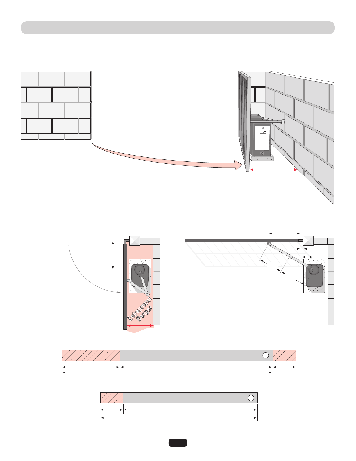
6
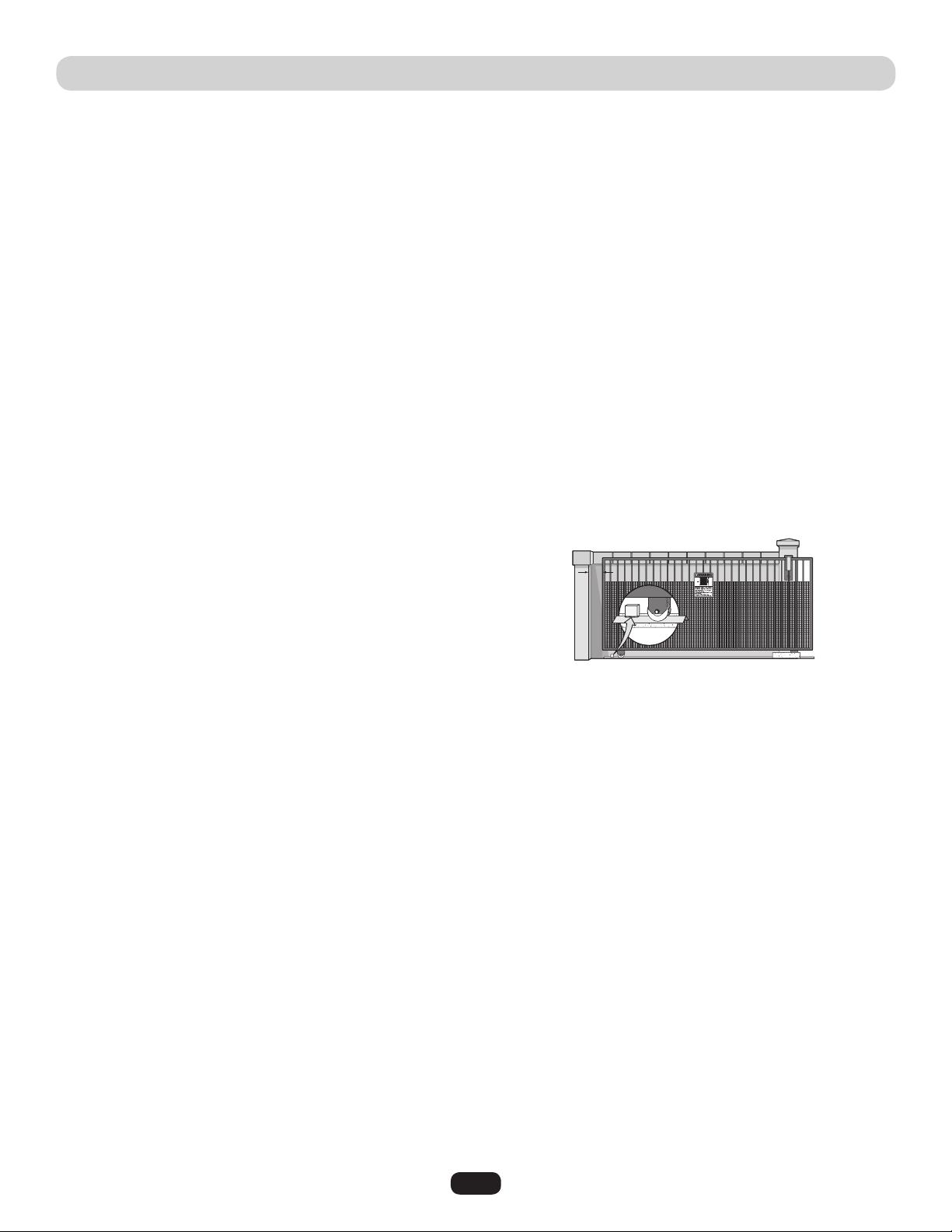
SUGGESTED ENTRAPMENT PROTECTION DEVICE LOCATIONS
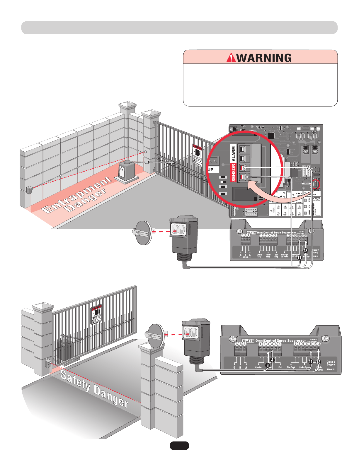
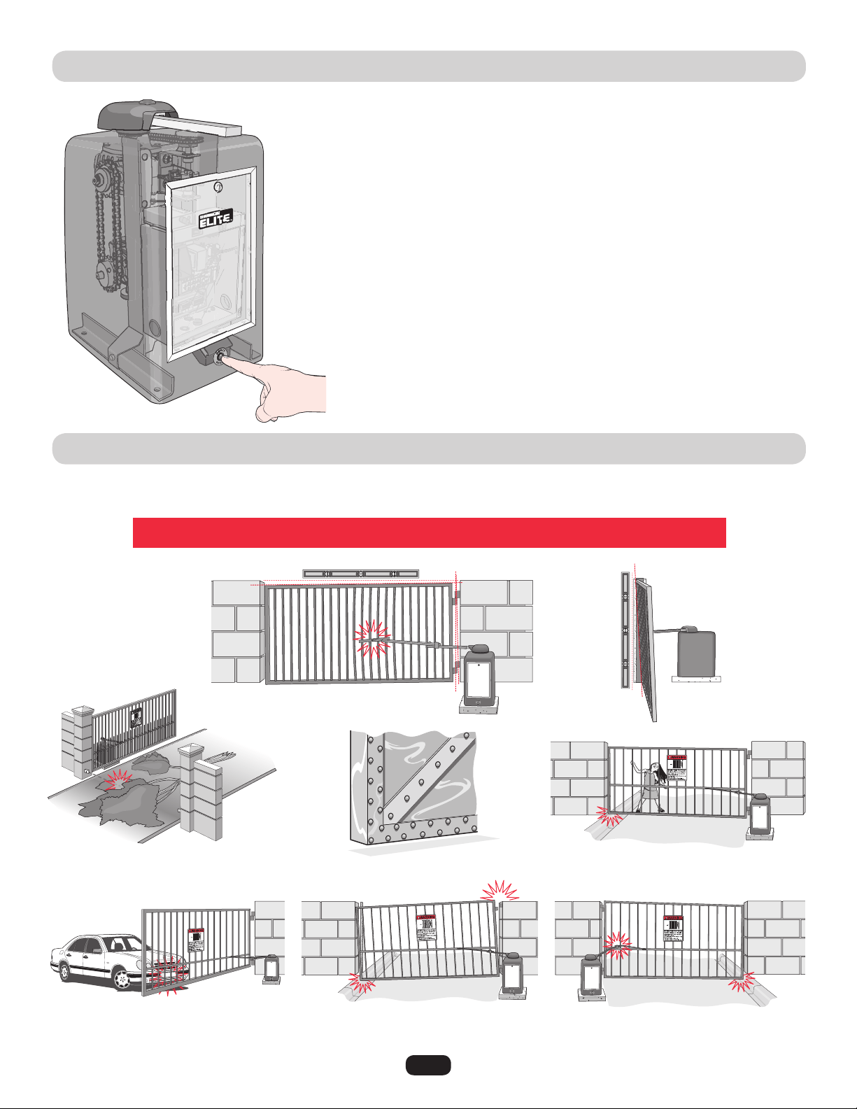
To prevent SERIOUS INJURY or DEATH from a moving gate:
• Entrapment protection devices MUST be installed to protect anyone who may come near a moving gate.
• Locate entrapment protection devices to protect in BOTH the open and close gate cycles.
• Locate entrapment protection devices to protect between moving gate and RIGID objects, such as posts or walls.
• A swinging gate shall NOT open into public access ways.
Install photoelectric sensors to protect
against any entrapment or safety conditions
encountered in your gate application.
Safety loops allows the gate to
stay open when vehicles are
obstructing the gate path.
Suggested for vehicles 14 feet or
longer. If a vehicle is shorter, a
center loop is recommended and
should be installed.
Non-Contact Sensors (Photoelectric Sensors)
A center loop protects during a
Close cycle of the gate. Safety
loops are required when using a
center loop.
See Loop Wiring.
7
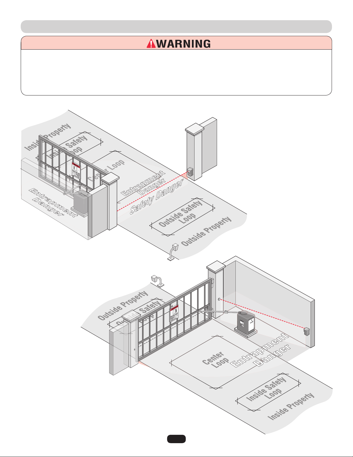
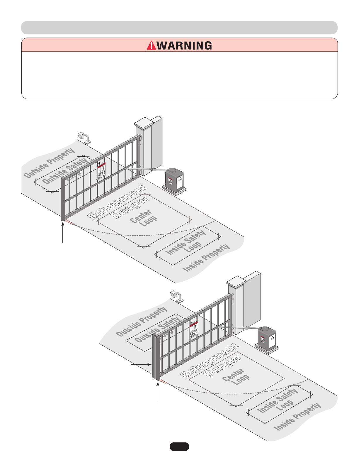
SUGGESTED ENTRAPMENT PROTECTION DEVICE LOCATIONS
To prevent SERIOUS INJURY or DEATH from a moving gate:
• Entrapment protection devices MUST be installed to protect anyone who may come near a moving gate.
• Locate entrapment protection devices to protect in BOTH the open and close gate cycles.
• Locate entrapment protection devices to protect between moving gate and RIGID objects, such as posts or walls.
• A swinging gate shall NOT open into public access ways.
Contact Sensors (Edge Sensors)
Install edge sensors to protect against any
entrapment or safety conditions encountered in your
gate application.
See Entrapment Protection Devices.
Edge sensor for open cycle.
Edge sensor for close cycle.
3 sided edge sensor for open
and close cycle.
Safety loops allows the gate to
stay open when vehicles are
obstructing the gate path.
Suggested for vehicles 14 feet
or longer. If a vehicle is shorter,
a center loop is recommended
and should be installed.
A center loop protects during the
Close cycle of a gate. Safety
loops are required when using a
center loop.
See Loop Wiring.
8
To prevent SERIOUS INJURY or DEATH from a moving gate:
• Entrapment protection devices MUST be installed to protect
anyone who may come near a moving gate.
• Locate entrapment protection devices to protect in BOTH
the open and close gate cycles.
• Locate entrapment protection devices to protect between
moving gate and RIGID objects, such as posts.
• A swinging gate shall NOT open into public access ways.
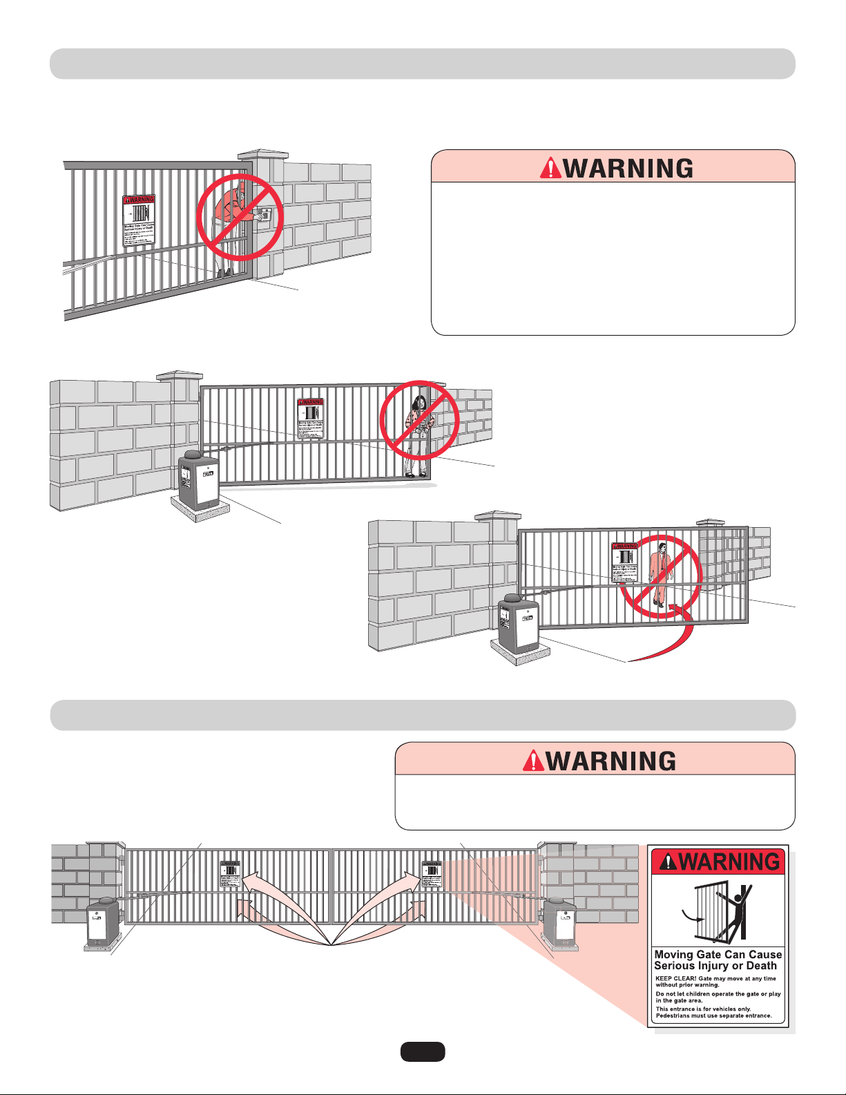
SAFETY PRECAUTIONS
Property owners MUST never mount any gate
operating device near the gate's path!
Property owners MUST never allow
anyone to hang or ride on the gate!
Property owners MUST never let pedestrians cross the path of a moving gate!
WARNING PLACARD PLACEMENT
40-50399A
THE CSW200UL™ IS FOR USE ON VEHICULAR PASSAGE GATES ONLY
AND NOT INTENDED FOR USE ON PEDESTRIAN PASSAGE GATES.
To prevent SERIOUS INJURY or DEATH from a moving gate:
Install warning placards on BOTH sides of EACH gate in PLAIN VIEW.
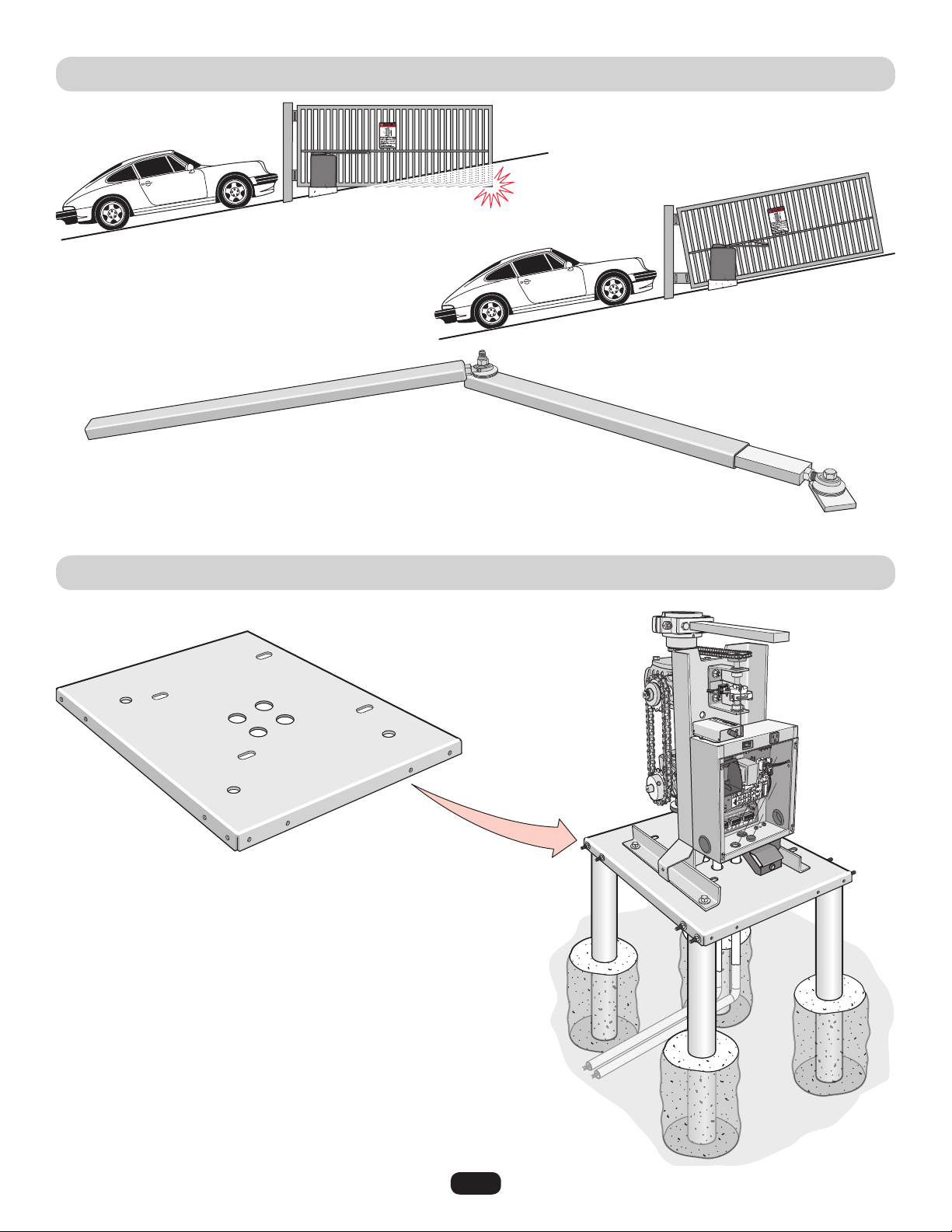
9
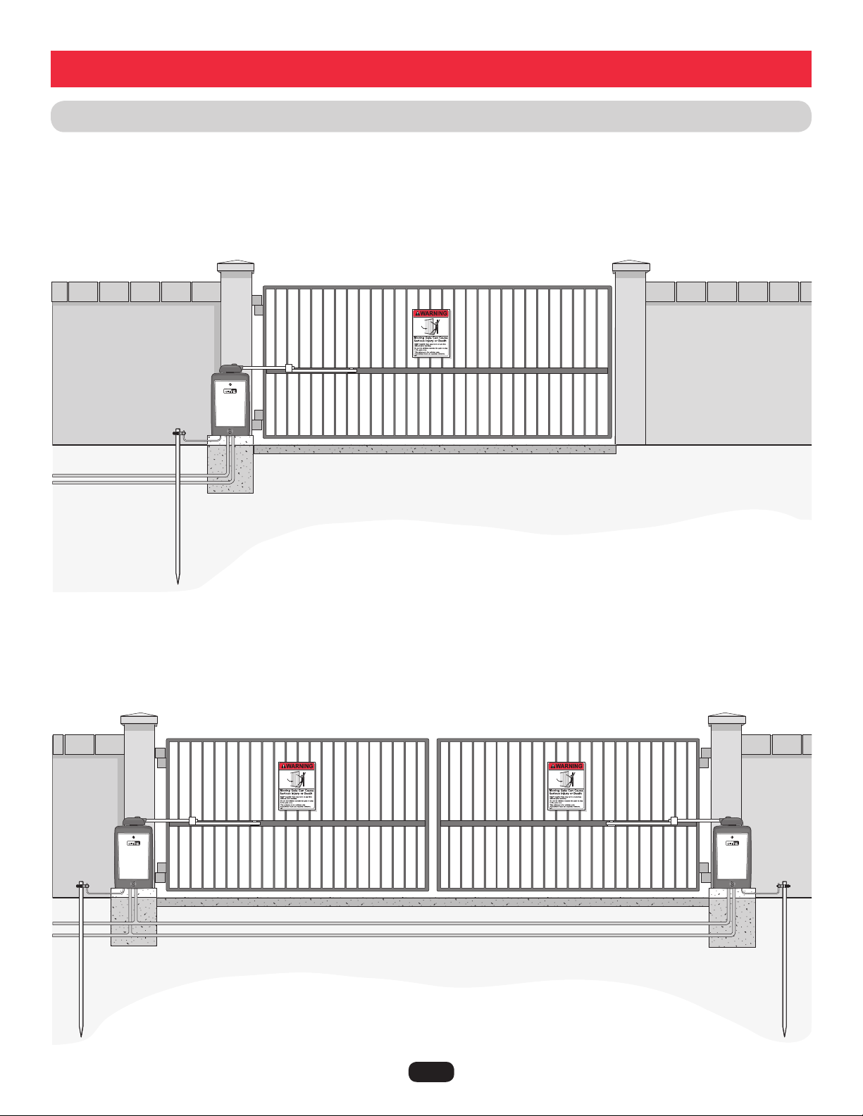
INSTALLATION SETUPS
Installation
Master/Second Operators
Single Operator
Low Voltage UL
approved conduit
Low Voltage UL approved conduit
High Voltage UL
approved conduit
Concrete Pad
Concrete Pad
Concrete Pad
Earth Ground Rod is highly recommended.
Earth Ground Rod is highly recommended
for each operator.
Separate power supply for each operator.
Maximum gate length 20 ft. (22 ft. for 1HP)
Maximum gate weight is 600 lbs. (800 lbs. for DM) (1000 lbs. 1HP)
Maximum gate length 20 ft. (22 ft. for 1HP)
Maximum gate weight is 600 lbs. (800 lbs. for DM) (1000 lbs. 1HP)
High Voltage UL approved conduit
Warning Placard on both sides of gate.
Warning Placard on both sides of each gate.
NOTE: Weld a horizontal bar
across entire gate on any
installation for strength.
10
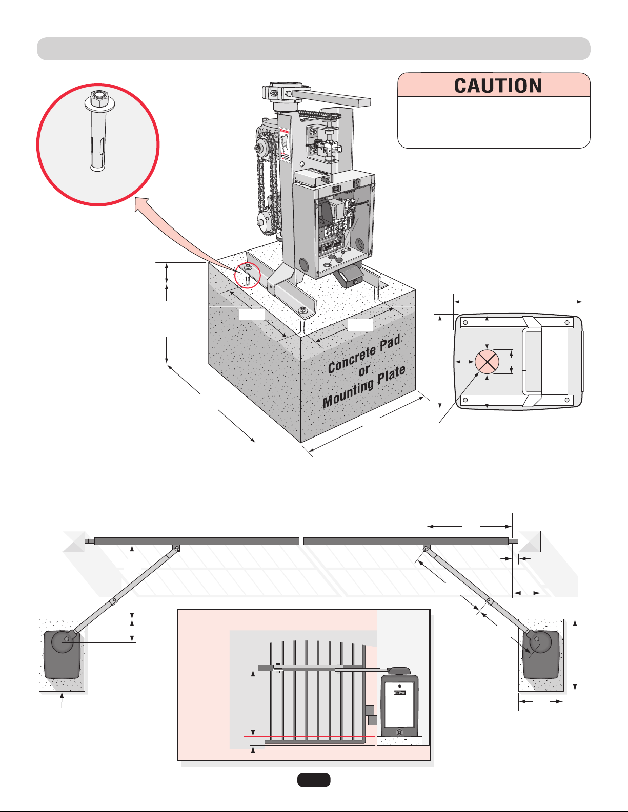
CONCRETE PAD AND ARM ATTACHMENT
Below the Frost
Line Check all
Local Codes
Concrete Anchors
1/2" x 3-1/2"
6"
Above
Ground
28"
Post
Concrete Pad
Bracket Height
Concrete Pad Height
Long Arm
Using Standard Arm
Short Arm
Hinge Center
Drawing not to scale
24"
Sample of Standard Arm Attachment
(See next page for layout)
28"
46"
25"
35.5"
29.5"
24"
11"
10"
27.5"
Long Arm is
on Top of
Bracket!
Bottom of CSW
2"
Outside Property
Inside Property
14"
3-5/8"
5-1/4"
3-7/8"
5-1/4"
Electronic Box
19"
Top View of Chassis
Approximate placement of high
voltage and/or low voltage
conduits.
To AVOID damaging operator, DO NOT
weld ANY supports to chassis. Chassis
MUST be allowed to flex during operation.
10.3"
10.4"
11
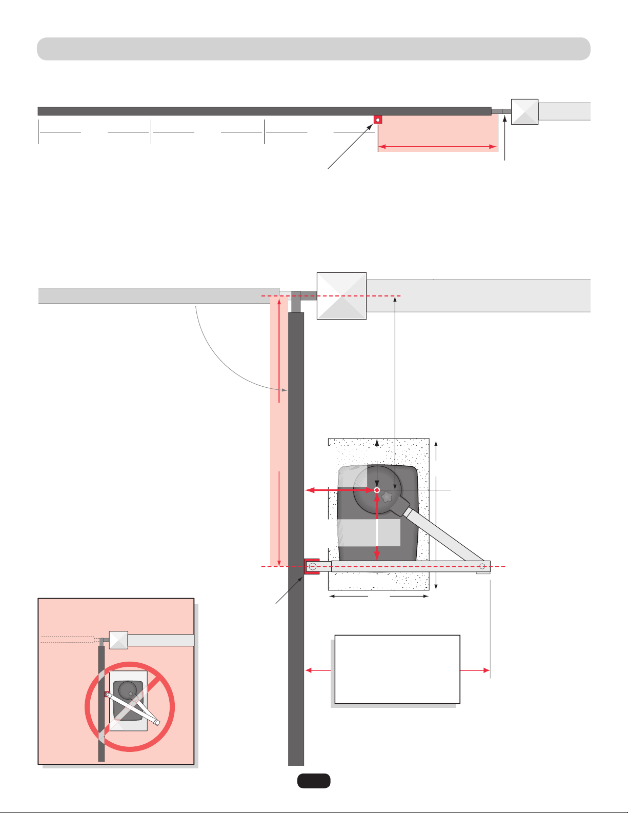
STANDARD INSTALLATION LAYOUT
Sample of standard arm attachment is shown on previous page.
Drawing not to scale
Top View of Closed Gate
Top View of in Open Position
1/4
Bracket Position
Long arm
is on TOP
of
bracket.
Mount bracket at least a quarter of the gate length from the gate hinge.
Gate Hinge
Gate Hinge Center
Output Shaft Center
Important Note:
If this dimension is between
20 and 32 inches, “Compact
Installation” is necessary.
(Refer to next page.)
Short Arm
Long Arm
24"
Concrete Pad
28"
10"
Bracket Length Minus 8"
(Minimum)
1/41/4
Bracket Length
Arm must be 90° from Gate
Bracket Length
Gate Open 90°
Helpful Layout Note:
A) Long arm’s final placement is on TOP of
bracket.
B) Tack weld bracket in position.
C) Close gate, place tape measure between
bracket and output shaft.
D) With tape between bracket and output shaft,
open gate and bend tape until tape is 90°
from gate.
E) Take measurements of arms from bend in
tape measure.
DO NOT allow arms to
scissor when open.
For technical support: 1-800-528-2806
NOTE: Longer gates or retro-fits may require both arms to be lengthened by equal parts.
8" Minimum to avoid
scissoring of arms
9" Minimum
for Gate
Clearance
12
COMPACT INSTALLATION LAYOUT
Compact Installation ONLY!
DO NOT use these measurements for a standard installation.
(For standard installation, see previous page.)
It is necessary to protect against the entrapment that
could occur with this type of installation.
(See entrapment protection devices.)
20" Minimum
Width
20" to 32"
33"
23"
22"
36"
20"
24"
10"
4"
4"
25.5"
26.5"
2"
Cut Cut
Cut
9"
Hinge Center
Outside Property
Follow the exact measurements, then cut the standard arm to meet the shorter measurements.
Inside Property
Gate Closed
Outside Property
Inside Property
Gate Open
Long Arm
Short Arm
13
Not Possible
Gate hits driveway.
Possible
Special swivel arm and hinges are required.
Swivel Arm
UPHILL DRIVEWAY INSTALLATION (OPTIONAL)
POST MOUNTING PLATE INSTALLATION (OPTIONAL)
3" heavy steel posts can be
U-bolted to mounting plate and
cemented in ground.
Power and control
wiring can be run in
separate conduits.
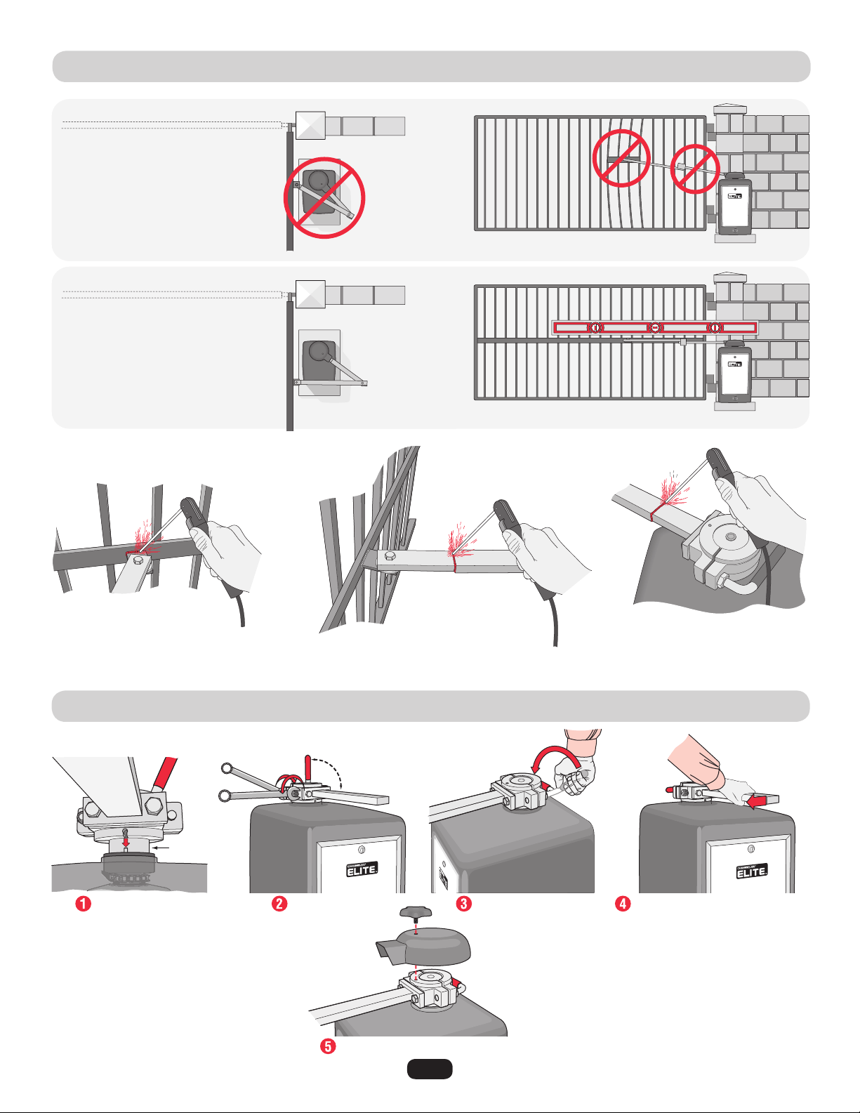
14
GATE ARM INSTALLATION
OUTPUT SHAFT ADJUSTMENT
Gate Closed
Incorrect
Installation!
Completely weld around the rectangular tubes and bracket!
Correct
Installation
Gate Open
Once the gate arm measurements are calculated:
Weld the bracket on the gate.
Fit pin in slot. Tighten the nut.
Output Shaft
Red handle
must be in
90° position
Tighten the handle.
Replace cover and star knob.
Pull the short arm away
from the gate.
NO slippage should occur.
If it does, go back and
tighten the nut.
Weld the longer arm.......... ........then weld the shorter arm.
Arm is on TOP
of bracket.
15
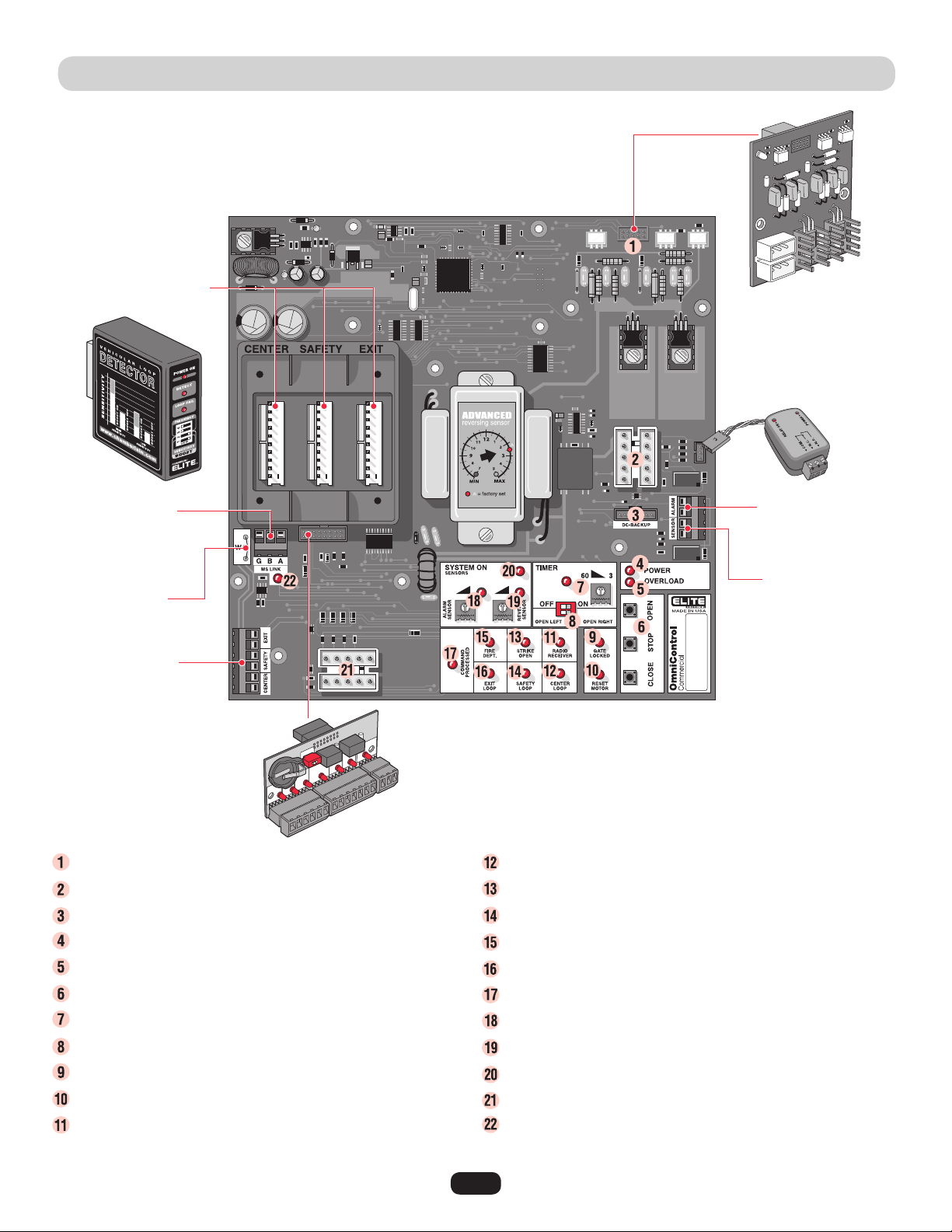
CONTROL BOARD DESCRIPTION
1HP Connection - Factory installed CSW200UL1HP™ Models.
J3 Motor, Limit Switch, Maglock/Solenoid Connection
DC2000™ Back-Up Power or Reset Switch Connection
Circuit Board Power LED - Operator power OK when ON.
Overload LED - Operator power has overloaded when ON.
On-Board 3 Button Station - Close, Stop, Open commands.
Timer - Timed close.
Gate Opening Direction Selector - Open Left, Open Right.
Gate Locked LED - Maglock/Solenoid is activated when on.
Reset Motor LED - Cycle operator power when ON.
Radio Receiver LED - Radio transmitter is activated when ON.
Center Loop LED - Center loop detector activated when ON.
Strike Open LED - Strike connected device activated when ON.
Safety Loop LED - Safety loop detector activated when ON.
Fire Dept LED - Key Switch activated when ON.
Exit Loop LED - Exit loop detector activated when ON.
Command Processed LED - Successful command executed.
Alarm Sensor - Limited Adjustment.
Reverse Sensor - Gate hit obstruction when ON.
System On LED - Operator is successfully performing a command.
J1 Surge Suppressor Data Connection
M/S Link LED - Data being transferred between master and second
operators when ON.
Maglock/Solenoid
Relay Module Connection
Plug-In Loop Wires
W4 Jumper Wire
UL Alarm Connection
Photoelectric
Sensor Connection
1 HP
Board
OmniControl™ Board Connection
Plug-In Loop Detectors
Surge Suppressor
Master/Second
Connection

16
Card Reader
External 120Vac “Exit” Loop Detector
12Vdc Failsafe Photoelectric Sensor
External 120Vac “Safety” Loop Detector
Second Operator Link
Push Button
Telephone Entry System
Fire or any Key Switch
NOTE: Terminals 11 and 12 are the ONLY terminals that will
Open and Close with a single push of a button. All other
terminals will ONLY Open with a single push of a button.
Output Power
Ground
24Vdc
Remote NOT Included
315 MHz Factory Installed Radio Receiver
Dry Contact
Dry Contact
Separate power
for card reader.
Separate Power
Separate Power
Separate power
for TES.
120Vac
Power
Removable
Terminals
Master/Second
Connection
SURGE SUPPRESSOR TERMINAL CONNECTIONS
To ENSURE proper operation of external devices:
• ENSURE bare wires make good contact inside
removable terminal connections.
• DO NOT let wire insulation interfere with
connection.
OR
17
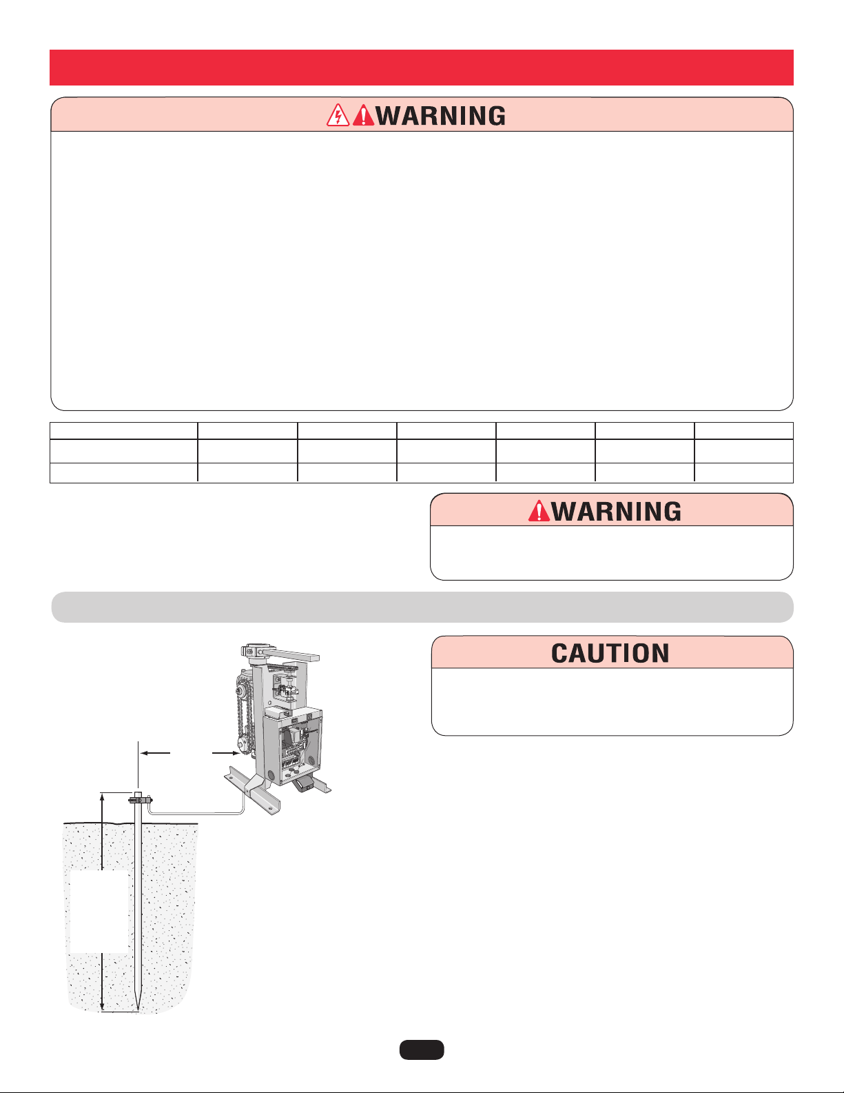
EARTH GROUND ROD INSTALLATION
To reduce the risk of SEVERE INJURY or DEATH:
• ANY maintenance to the operator or in the area near the
operator MUST not be performed until disconnecting the
electrical power and locking-out the power. Upon completion
of maintenance the area MUST be cleared and secured, at
that time the unit may be returned to service.
• Disconnect power at the fuse box BEFORE proceeding.
Operator MUST be properly grounded and connected in
accordance with local electrical codes.
NOTE: The operator should be on a separate fused line of
adequate capacity.
• ALL electrical connections MUST be made by a qualified
individual.
• DO NOT install ANY wiring or attempt to run the operator
without consulting the wiring diagram. We recommend that
you Install an optional reversing edge BEFORE proceeding
with the control station installation.
• ALL power wiring should be on a dedicated circuit and well
protected. The location of the power disconnect should be
visible and clearly labeled.
• ALL power and control wiring MUST be run in separate
conduit.
• BEFORE installing power wiring or control stations be sure to
follow ALL specifications and warnings described below.
Failure to do so may result in SEVERE INJURY to persons
and/or damage to operator.
• DO NOT disconnect the built-in audio alarm or reset switch.
Proper grounding gives an electrical charge, such as from an electrical static
discharge or a near lightning strike, a path from which to dissipate its energy
safely into the earth.
Without this path, the intense energy generated by lightning could be directed
towards the gate operator. Although nothing can absorb the tremendous power of a direct lightning
strike, proper grounding can protect the gate operator in most cases.
The earth ground rod must be located within 3 feet from the gate operator. Use the proper type earth
ground rod for your local area. The ground wire must be a single, whole piece of wire. Never splice
two wires for the ground wire. If you should cut the ground wire too short, break it, or destroy its
integrity, replace it with a single wire length.
To AVOID damaging gas, power, or other underground utility
lines, contact underground utility locating companies BEFORE
digging more than 18 inches (46 cm) deep.
Wiring
110Vac Power Wire
1/2 HP and Dual Motor
1 HP
16 Gauge
up to 150 FT
up to 75 FT
14 Gauge
250 FT
125 FT
12 Gauge
400 FT
200 FT
10 Gauge
650 FT
325 FT
8 Gauge
1000 FT
500 FT
4 Gauge
2200 FT
1100 FT
To prevent SERIOUS INJURY or DEATH from a moving gate:
DO NOT disconnect the built-in audio alarm or reset switch.
3 Feet
Single
piece of 12
gauge wire.
Check
local
codes for
proper
depth.
18
110Vac Power Wire
1/2 HP and Dual Motor
1 HP
16 Gauge
up to 150 FT
up to 75 FT
14 Gauge
250 FT
125 FT
12 Gauge
400 FT
200 FT
10 Gauge
650 FT
325 FT
8 Gauge
1000 FT
500 FT
4 Gauge
2200 FT
1100 FT
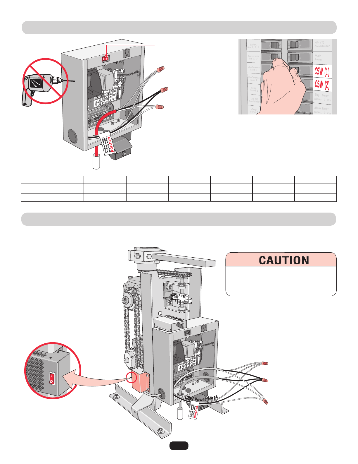
110Vac POWER CONNECTION
HEATER POWER CONNECTION
Earth Ground Rod Highly Recommended!
See previous page.
Use a 20 amp dedicated circuit for each operator.
Input power 120Vac, 60 Hz.
On-Off switch for operator
Green Ground
Black 110Vac
White Neutral
Green Wires Ground
Black Wires 110Vac
White Wires Neutral
Power supply in
waterproof conduit.
Power
Supply
Connect the black, white and ground wire from the heater to the 110Vac power supply as shown. When the heater switch is left in the
“ON” position, the heater will turn on and off automatically when needed.
Switch should left in the
“ON” position.
To reduce the risk of SERIOUS INJURY:
DO NOT touch the heater when switch is
on, heater may be hot.
19
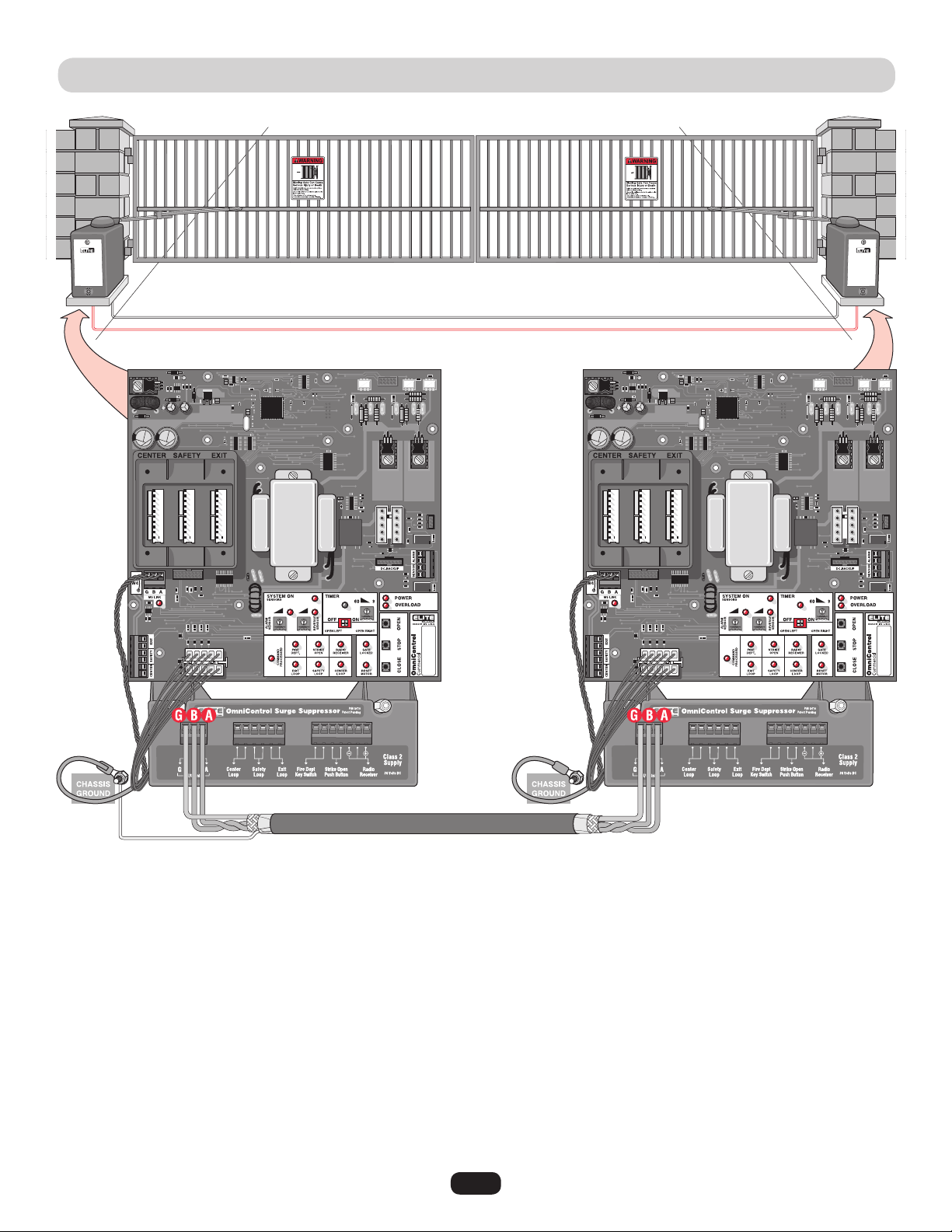
LINKING MASTER / SECOND OPERATORS
Run low voltage 16-18 gauge wire in UL approved conduit to link operators together.
Never run high voltage and low voltage wires in same conduit.
Use a 20 amp dedicated power circuit for each operator.
Master Board
Second Board
Connect Master M/S Link G to Second M/S Link G.
Connect Master M/S Link B to Second M/S Link B.
Connect Master M/S Link A to Second M/S Link A.
NOTE: Disconnect the second
radio receiver when using a
master/second setup.
NOTE: To adjust
timers, see page 31.
Surge
Suppressor
Master/
Second
Connection
Shield Wire
Master/Second control boards are interchangeable.
In order for the following operation to occur, follow the instructions.
Example: There is a double gate, the entry gate is to be opened with a remote control and the exit gate with a free exit loop. Only one
safety loop system is to open both gates, and a fire department switch should open both gates at the same time.
1. Connect the radio receiver to entry gate only.
2. Connect the exit loop to exit gate only.
3. Connect the safety loop to both entry and exit gates (observe polarity of voltage).
4. Connect the fire department switch to both entry and exit gates (observe polarity of both operators).
Use shielded
twisted wires for
M/S link.
Shield wire MUST
be grounded to
master operator
Only.
Partial Master/Individual Control
20
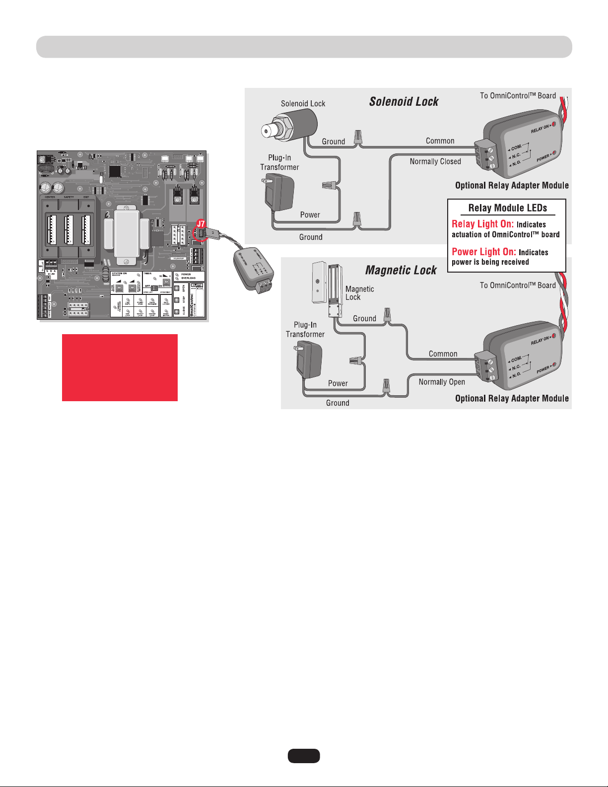
SOLENOID/MAGLOCK RELAY CONNECTION
Connection of a solenoid or magnetic lock can be made using the J7 board connector and “Optional” Relay Adapter Module.
Relay Contact Rating
2 Amp - 125 AC/DC
2 Amp switching load
capability
21
CLASS I, II, III, IV
Socket
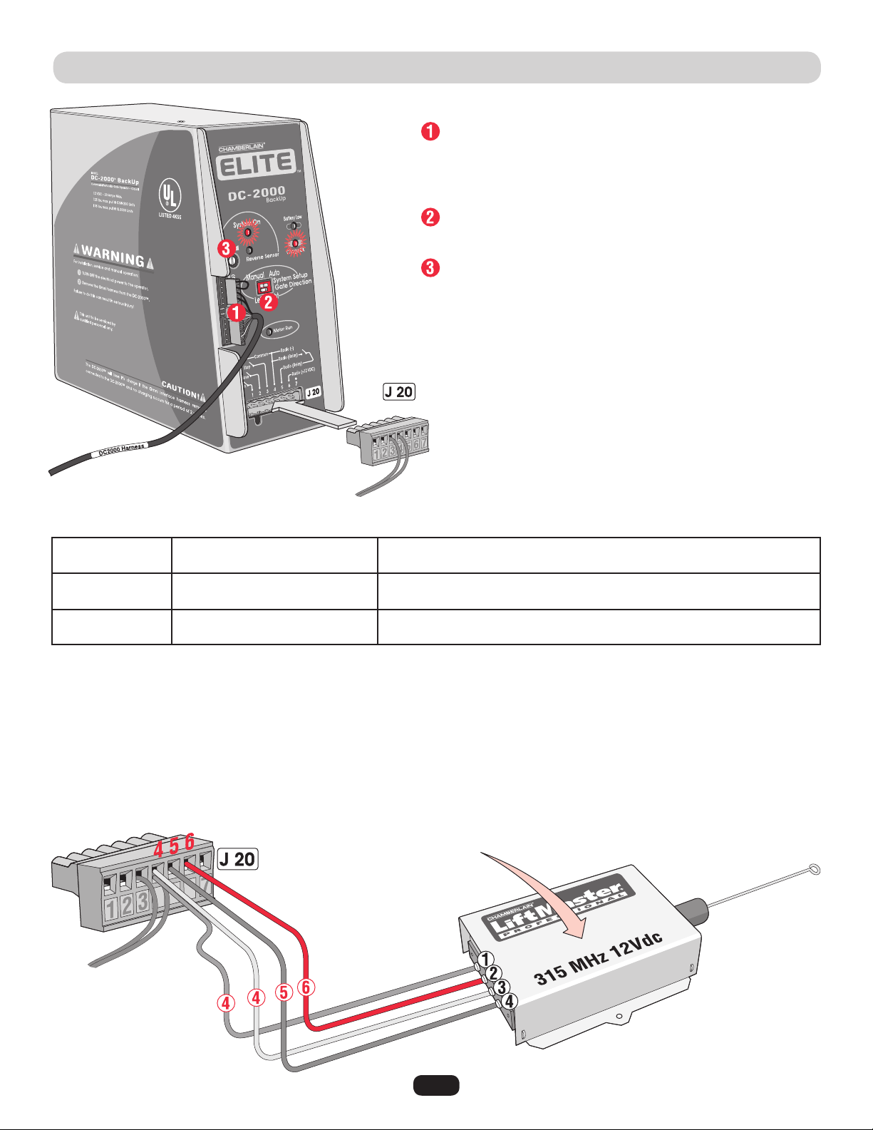
FACTORY INSTALLED DC2000™ CONNECTION
DC2000™ 12Vdc Radio Receiver (Not Provided)
The DC2000™ needs a separate 12Vdc radio receiver to give remote commands to the operator during a power failure.
+12Vdc
Jumper P2:
to Constant (C)
Jumper P3:
to 12 Volt
NOTE: Refer to page 29
and 30 for programming
radio receiver.
DC2000™ Startup
Plug in the 12 pin plug into the DC2000™ control unit. Make sure
the “System ON” and “Charge OK” LEDs are lit. If the “Battery Low”
led comes on, the battery needs to charge before it can be used.
Make sure “Gate Direction” setting on DC2000™ is set the same as
the OmniControl™ board setting. See Adjustments.
Adjust “Reverse Sensor” setting. See Adjusting Reverse Sensor(s).
Reset button and interlock wires, Do Not Remove.
Push and Hold to operate gate.
Gate automatically opens.
Turn the 110Vac power off then push and Hold to operate gate.
Turn the 110Vac power off then gate opens automatically.
110Vac Power Failure
110Vac Power On,
OmniControl™ Board Malfunction
Auto Mode
Manual Mode
NOTE: All devices wired to the DC2000™ MUST be dedicated to it alone. Normal operation will be controlled by separate devices wired
to the OmniControl™ board and surge suppressor.
Example: If the DC2000 is “automatically opening” the gate due to a power failure (auto mode), any manual command such as
“One-Button”, “Three Push Button”, “Key Switch”, “Photoelectric Sensor” or “Edge Sensor” will cancel the automatic mode of the
DC2000™. After such cancellation, the DC2000™ will continue to operate in “manual mode” until 110Vac power is restored.

22
DC2000™ DEVICE WIRING
Manually Operated DC2000™ Devices
Manual external devices should be dry-contact which do not consume any current like push buttons or a key switch.
Key switch is for property owner’s emergency access ONLY. DO NOT FOR USE FOR A EMERGENCY FIRE/POLICE KEY ACCESS.
Contact your local Fire/Police municipalities for more information on correct Fire/Police emergency key access.
DC2000™ Entrapment Protection Devices
It is recommended using separate entrapment protection devices to maintain gate safety when the DC2000™ is needed for any reason.
The entrapment protection devices connected to the OmniControl™ board and surge suppressor WILL NOT protect the gate when there
is a AC power failure and the DC2000™ is used.
ComN.O.
N.O.
N.O.
Com
Ground
+12Vdc
Com
Push and HOLD button to Open.
Push button again and HOLD to Close.
OmniControl™ Board
Sensor Connection
Push and HOLD a button to operate.
Turn and HOLD key to Open.
Turn key again and HOLD to Close.
Manual One-Button
3 Edge Sensor
12Vdc Failsafe
Photoelectric
Sensor
Manual Three-Button
Key Switch
(See Accessories for part number.)
Failsafe Photoelectric Sensor: If a photoelectric sensor is not working, loses power or
photoelectric sensor is blocked, then the photoelectric sensor will stop all gate operation.
23
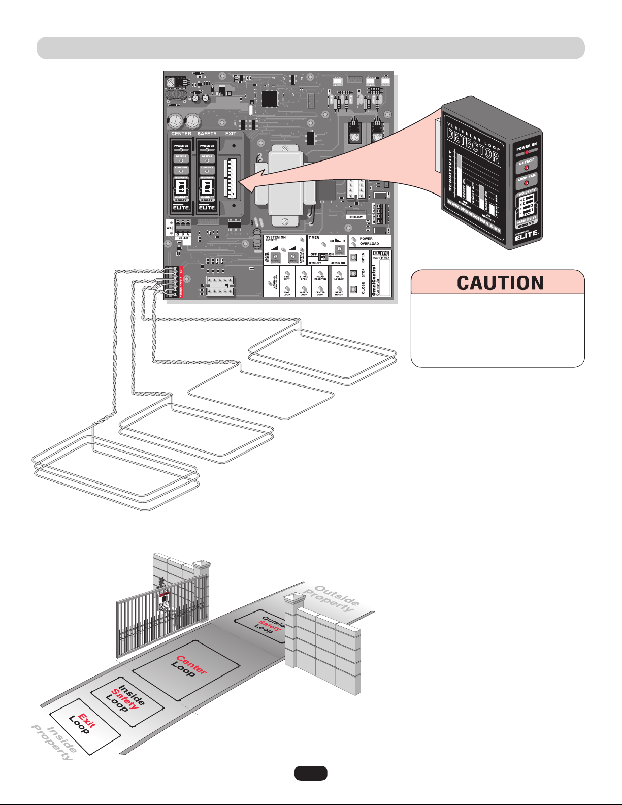
PLUG-IN LOOP DETECTOR WIRING
Plug-In Loop Detectors
(Sold Individually)
Contact your local dealer for information
about plug-in loop detectors.
The wire MUST be
twisted together
6 twists per foot
from the end of
the loop to the
control board.
NOTE: Refer to the plug-in
loop detector manual for
more specific information.
Plug-In “Center” Loop Detector: Allows gate to
stay open when vehicles are obstructing path.
Caution: This option is for all vehicles including
ones less than 14 feet long. Center loop system
requires two safety loops.
Example of a 1 wire loop. (See “Installing
Insulated Loop Wire” on next page for more
information.)
Plug-In “Safety” Loop Detector: Allows gate to
stay open when vehicles are obstructing path.
Caution: Suggested for vehicles 14 feet or longer.
If the “Inside” and “Outside” safety loops are
connected to the same loop detector:
• They should be series connected to the detector.
• Have the same dimensions.
• Have the same number of wire turns.
Example of a inside and outside 2 wire turn loop
connected in series. (See “Installing Insulated
Loop Wire” on next page for more information.)
Plug-In “Exit” Loop Detector: Allows gate to
automatically open for exiting vehicles.
Example of a 3 wire loop. (See “Installing
Insulated Loop Wire” on next page for more
information.)
To AVOID damaging control board,
disconnect all power to operator before
installing plug-in loop detectors.
Use a different frequency for every loop
detector installed.
Inside
Safety Loop
Outside
Safety Loop
Exit Loop
Center Loop
Series Connected
24
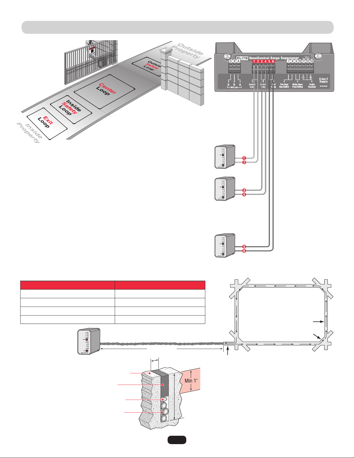
110Vac EXTERNAL LOOP DETECTOR WIRING
110Vac “Center” Loop Detector: Allows gate to stay open when vehicles are
obstructing path. Caution: This option is for all vehicles including ones less than
14 feet long. Center loop system requires two safety loops.
110Vac “Safety” Loop Detector: Allows gate to stay open when vehicles are
obstructing path. Caution: Suggested for vehicles 14 feet or longer. If a vehicle is
shorter, a center loop system is recommended and should be installed.
If the “Inside” and “outside” safety loops are connected to the same loop detector:
• They should be series connected to the detector.
• Have the same dimensions.
• Have the same number of wire turns. (See table below.)
110Vac “Exit” Loop Detector: Allows gate to automatically open for exiting
vehicles.
(Sold Individually)
10 feet to 13 feet
14 feet to 26 feet
27 feet to 80 feet
80 feet and up
4
3
2
1
The wire is continuously wound in
the loop saw cut for the required
number of turns. One turn shown
(refer to table).
Recommended Loop Wire XLPE 12-18 gauge
(Use heavier wire gauge for a more durable loop.)
Remove sharp inside corners
by making corner cuts.
The wire MUST be twisted together 6 twists per foot
from the end of the feeder slot to the loop detector.
Loop Perimeter
Number of Wire Turns Needed for Loop Sizes
Number of Wire Turns
Road Surface
Sealant
Feeder Slot
Saw Cut
1/8" to 1/4" Width Saw Cut
2" to 2.5" Depth
Saw Cut
NOTE: Use
separate 110Vac
power for each
loop detector.
Home Run
Backer Rod
Insulated loop wire
3 turns shown, amount varies.
Refer to table.
Contact your local dealer
for more information
about loop detectors.
NOTE: Wire mesh or reinforcement
imbedded in the road surface should be
cut away a minimum of 6 inches from
the perimeter of the loop.
Installing Insulated Loop Wire
Safety Loop
Exit Loop
Center Loop
25
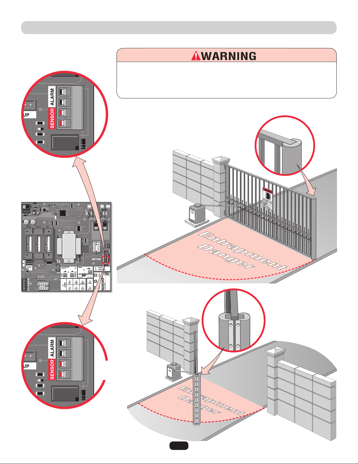
ENTRAPMENT PROTECTION DEVICES
NOTE: When touched, these electrically activated edge sensors immediately signal the gate
operator to stop and reverse. Property owners are obligated to test edges monthly.
UL Listed Edge Sensors
(See Accessories for part number.)
Connect both edge
sensors parallel to
sensor connector.
UL Listed 3 sided Edge Sensor
(See Accessories for part number.)
Open and Close
Contact Sensors
3 Edge
Contact Sensor
To prevent SERIOUS INJURY or DEATH from a moving gate:
• Locate entrapment protection devices to protect in BOTH the open and close gate cycles.
• Locate entrapment protection devices to protect between moving gate and RIGID
objects, such as posts or walls.
Open Sensor
Close Sensor
Contact Sensors (Edge Sensor)
Contact your local dealer for more
information about edge sensors.
26
ENTRAPMENT PROTECTION DEVICES
NOTE: If the photoelectric sensor gets
blocked while the gate is closing, it will
stop and reopen. The gate will remain
open until the obstruction is cleared.
Contact your local dealer for more
information about photoelectric sensors.
Safety Non-Contact Sensor
Entrapment Non-Contact Sensor
To prevent SERIOUS INJURY or DEATH from a moving gate:
• Locate entrapment protection devices to protect in BOTH the
open and close gate cycles.
• Locate entrapment protection devices to protect between
moving gate and RIGID objects, such as posts or walls.
NOTE: Property owners are
obligated to test photoelectric
sensors monthly.
Non-Contact Sensors (12Vdc Photoelectric Sensors)
It is best to use Failsafe Photoelectric
Sensors for this safety option.
Failsafe Photoelectric Sensors: If a failsafe
photoelectric sensor is not working or loses
power or photoelectric sensor is blocked, then
the photoelectric sensors will stop ALL gate
operation.
27
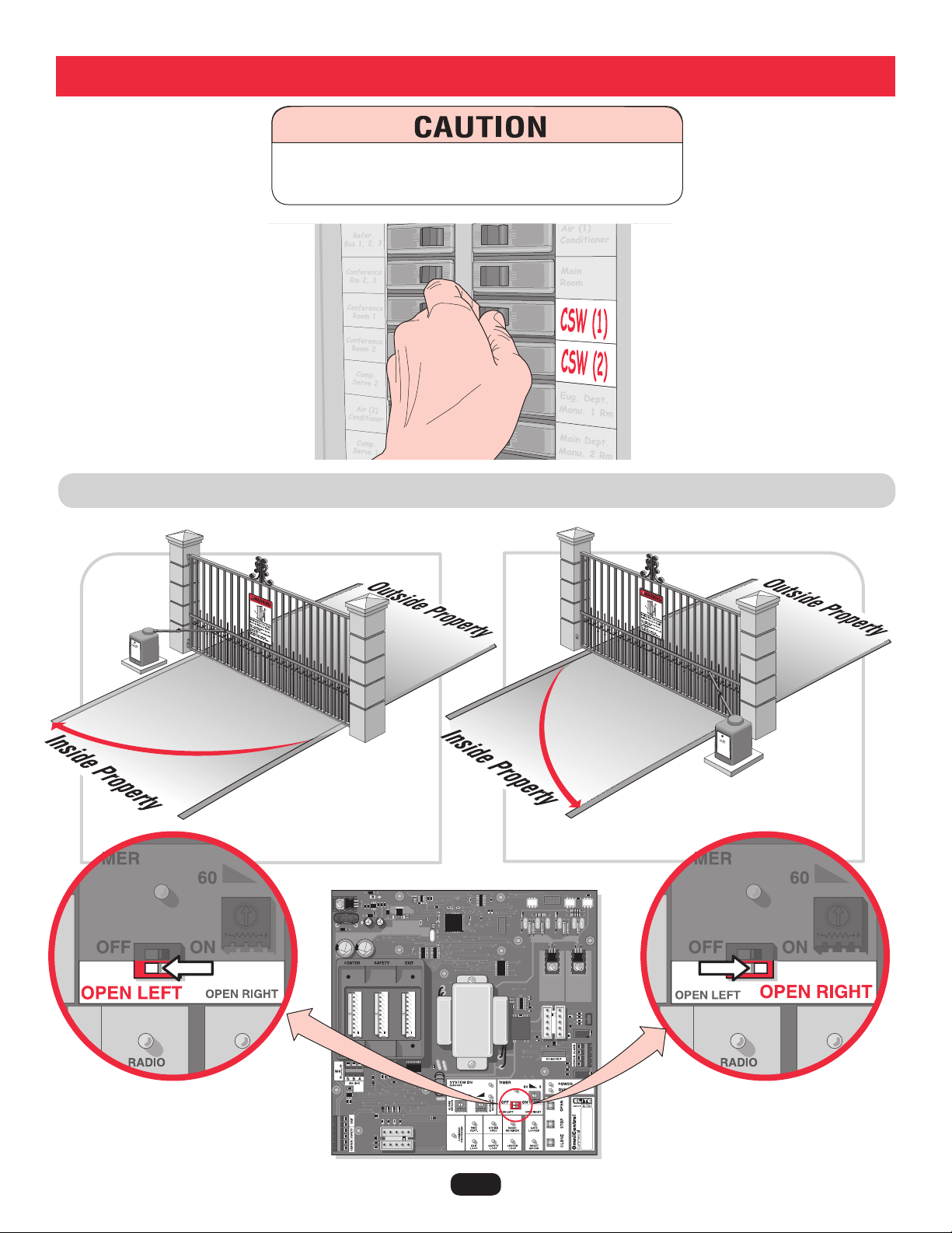
SET GATE OPENING DIRECTION
Open to the LEFT
Open to the RIGHT
To reduce the risk of SERIOUS INJURY or DEATH:
Disconnect power BEFORE performing ANY adjustments.
Adjustments
28
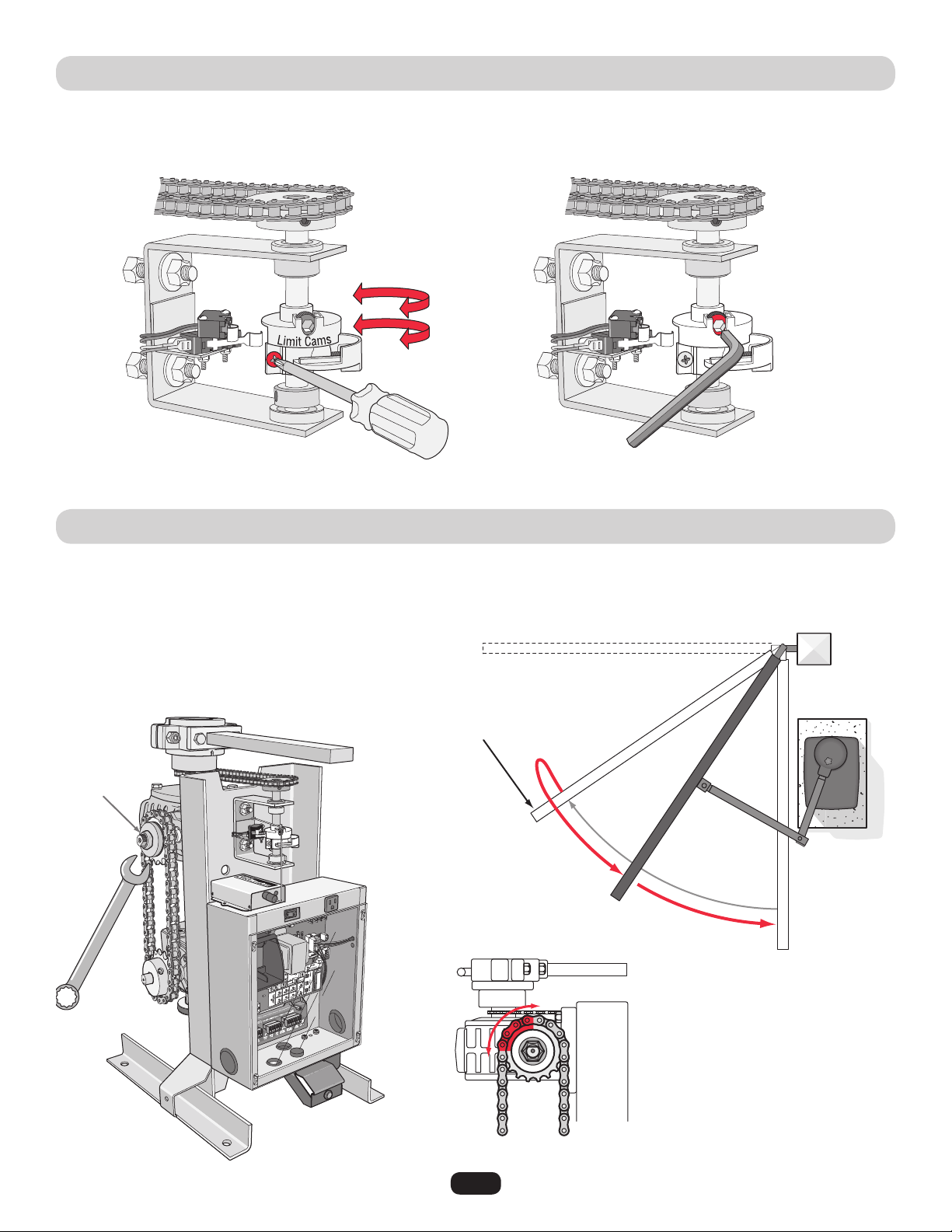
LIMIT SWITCH ADJUSTMENT
CLUTCH ADJUSTMENT
Release the red safety handle and move the gate to the open position. Loosen the screw on one of the limit cams and turn the cam
until the half moon shape hits the limit switch and you hear the switch click. Tighten cam. Move gate to the closed position and do the
same with the other limit cam. For a more precise adjustment, use the allen screw.
The adjustment is for a gate that is over 300 pounds and 12 feet long or longer. While the gate is closing, instantly an “open”
command is given as shown below; the clutch may slip a bit, max. of 1/4 to 3/4 of a turn (slippage depends on the weight of the gate).
If it does not slip, then readjust the clutch.
Loosen screws to turn limit cams.
Typical clutch slippage (1/4 turn)
Adjust the
clutch with
a wrench
Gate is given an “Open”
command before completing
a normal close-cycle.
Gate smoothly
reverses direction
with the clutch slipping
1/4 to 3/4 turn.
(Starting Position)
(Finishing Position)
Precise adjustment.
Gate in Closed Position
Gate in
Opened
Position
Allen
Screw
29
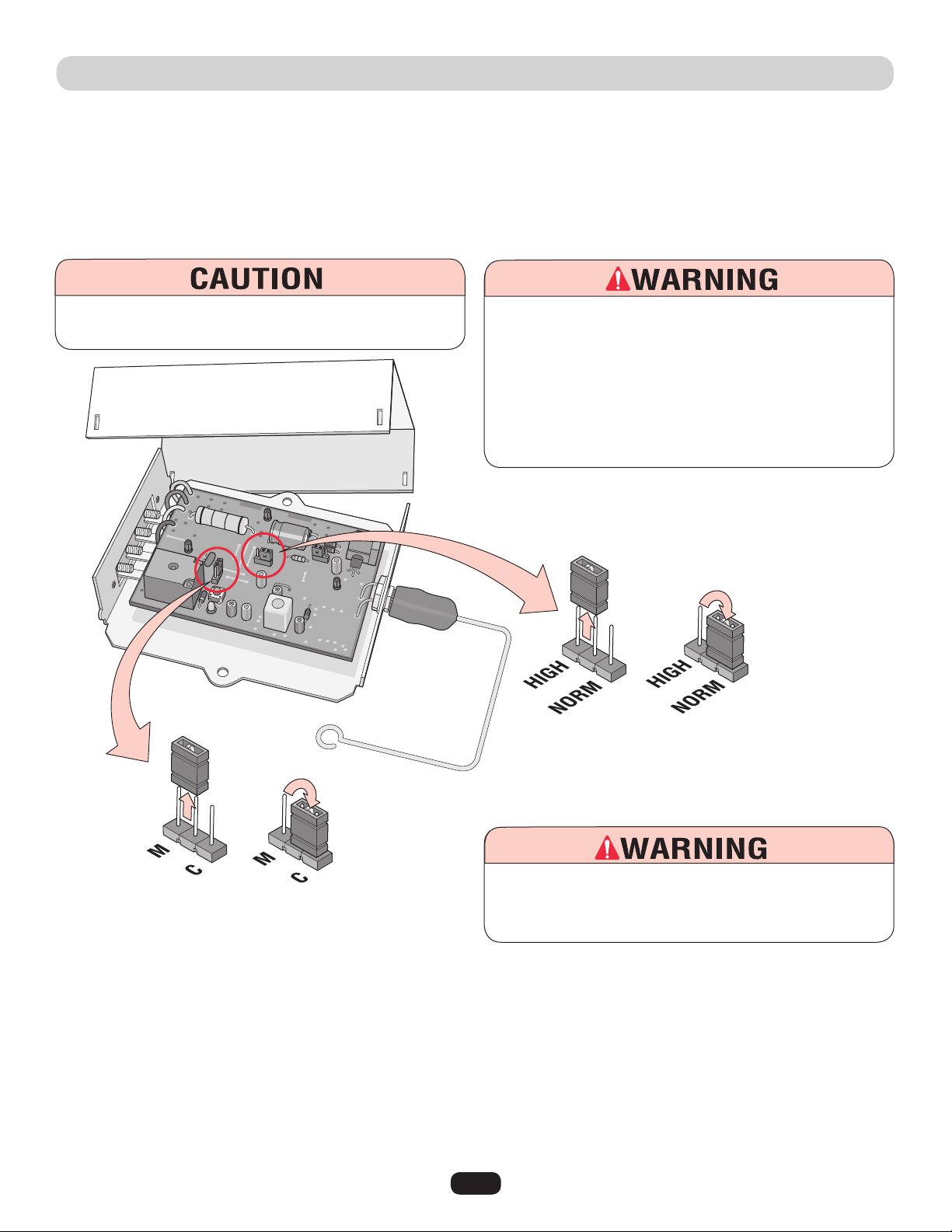
Setting Security Mode (High) or (Normal):
Setting Output Duration (M) or (C):
P4
P2
Changing security from High to Normal.
Changing output duration from Momentary to Constant.
The receiver is factory set at HIGH security mode. To verify, refer to the label next to jumper P4. (See illustration below.)
The Receiver can be used with up to 15 rolling code remotes or passwords in HIGH security mode. Alternately, it can be used with up
to 31 of any type remote in NORMAL security mode, including any combination of rolling code, billion code, or dip switch remotes.
When changing from NORMAL to HIGH security mode, all previous remote control codes must be erased. See next page to erase and
reprogram remote controls that are being used.
The receiver is factory set at (M) Momentary. To verify, refer to the label next to jumper P2. (See illustration above.)
For commercial applications, the receiver can be set to either (C) constant or (M) momentary closure.
With the jumper in the (M) momentary position, the contacts will close for 1/4 second regardless of the length of remote control
transmission.
With the jumper in (C) constant position, the contacts will stay closed as long as the remote control continues transmitting. Push and
HOLD remote button to open or close gate.
315 MHZ 24Vdc RADIO RECEIVER PROGRAMMING
To AVOID damaging receiver, disconnect receiver’s power
BEFORE changing jumpers.
To reduce the risk of SERIOUS INJURY or DEATH, the use of
CONSTANT OPERATION on residential operators is
PROHIBITED.
To reduce the risk of SERIOUS INJURY or DEATH from a
moving gate:
•
ALWAYS keep remote controls out of reach of children.
NEVER permit children to operate, or play with remote control.
•
Activate gate ONLY when it can be seen clearly, is properly
adjusted, and there are no obstructions in gate’s path.
•
ALWAYS keep gate in sight until completely closed. NEVER
permit anyone to cross path of a moving gate.
30
315 MHz 24Vdc RADIO RECEIVER PROGRAMMING
Programming Radio Receiver:
1. Press and release the “Learn” button on the
receiver. The learn indicator light will glow steadily
for 30 seconds.
2. Within 30 seconds, press and hold the button on the hand-held remote. The
operator will now operate when the push button on the remote control is pressed.
Repeat Steps 1 and 2 for each remote control that will be used.
Erase ALL Remote Control Codes:
Press and hold the “Learn ” button on the receiver panel until the indicator light turns
off (about 6 seconds). All previous codes are now erased. Reprogram each remote you
wish to use.
IMPORTANT: Hand-held remote NOT included.
NOTE: Disconnect the second receiver
when using a master/second setup.
NOTICE: To comply with FCC and or Industry Canada (IC) rules, adjustment or modifications of this receiver
and/or transmitter are prohibited, except for changing the code setting or replacing the battery. THERE ARE
NO OTHER USER SERVICEABLE PARTS.
Tested to Comply with FCC Standards FOR HOME OR OFFICE USE. Operation is subject to the following two
conditions: (1) this device may not cause harmful interference, and (2) this device must accept any
interference received, including interference that may cause undesired operation.
Learn
Button
Optional 315 MHz Hand Held Remotes - See Accessories
31
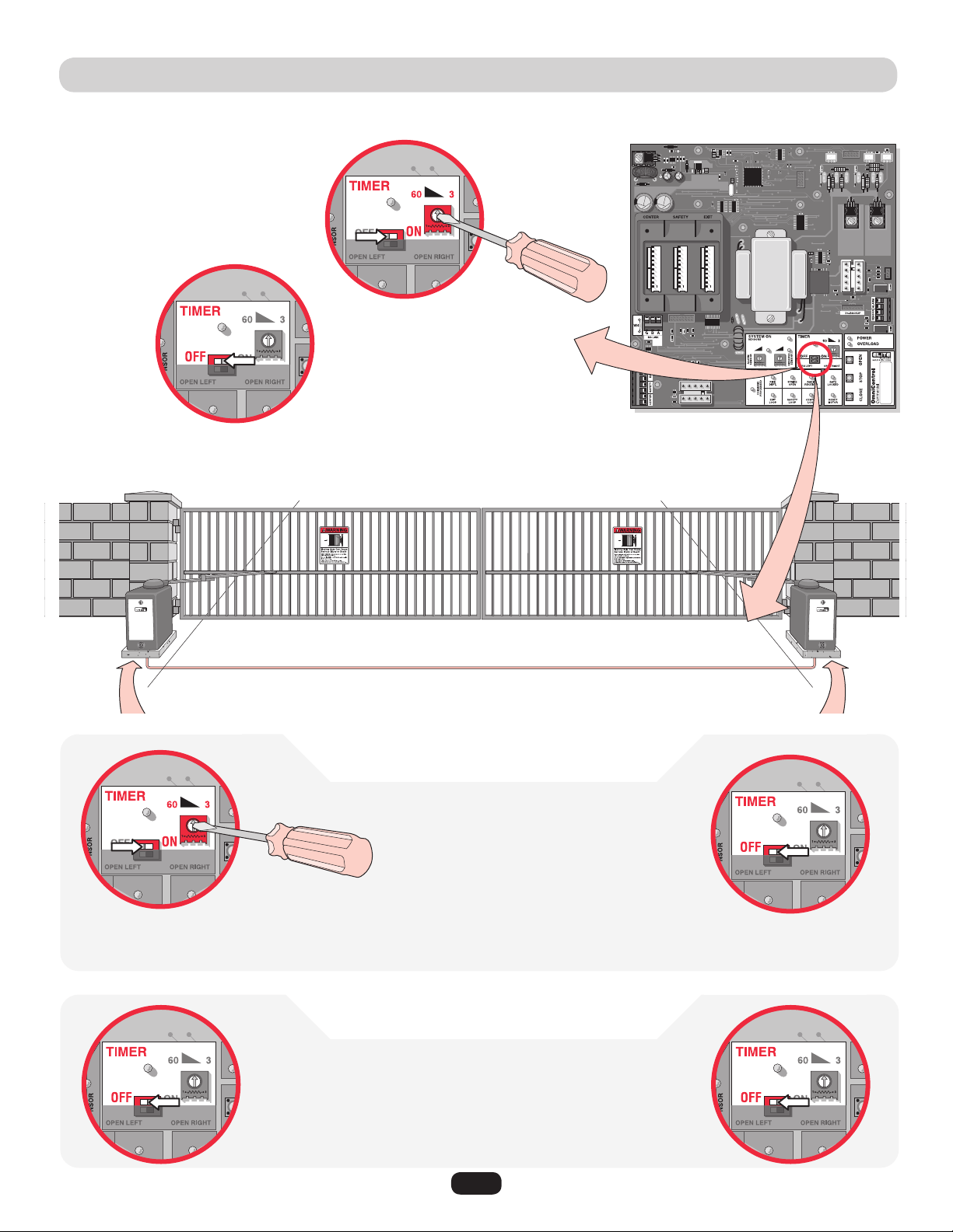
SETTING THE TIMER
To use the automatic close for the gate system
the timer switch should be put in the “ON”
position.
Set timer 3 to 60
seconds.
1. Turn MASTER timer ON.
2. Turn Second Timer to
Maximum Counterclockwise
Setting.
3. Use Timer on Master Board
Only. (3 to 60 seconds)
Master Board Second Board
Master Board
Second Board
1. Turn BOTH timers OFF.
Single Operator
Master/Second Operators
with Timers ON
with Timers OFF
Operators need to be connected by M/S LINK. See Linking Master page 19.
Master/Second control boards are interchangeable.
M/S LINK
NOTE: If a secondary photoelectric sensor
device is NOT used when the timer is ON, the
gate WILL hit a vehicle obstructing the gate
path before reversing during the close cycle.
To use the push close command,
the timer should be
switched to the
“OFF” position.
Push button
once to open
gate, push
button again to
close gate.
NOTE: Push button once to open gate, push
button again to close gate.
2. Turn SECOND timer OFF.
32
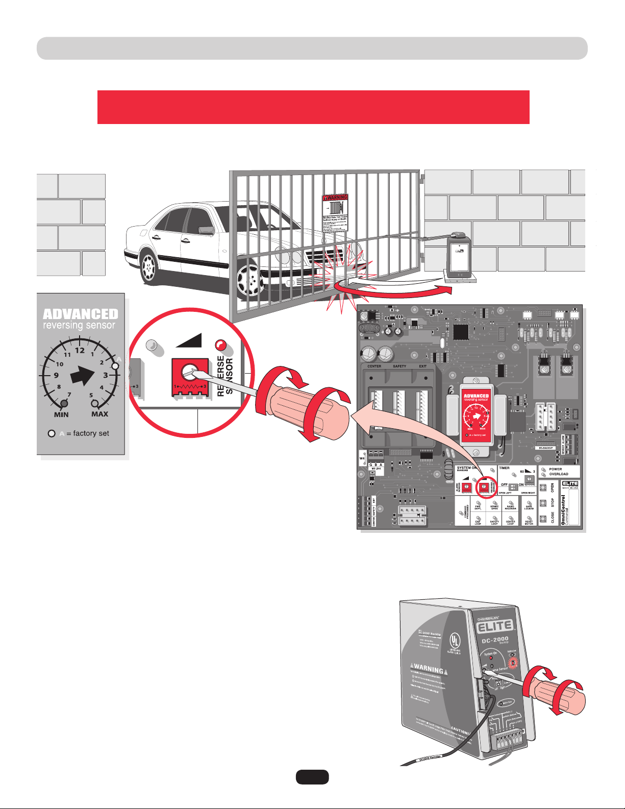
ADJUSTING REVERSING SENSOR(S)
The level of reverse sensitivity depends on the weight of the gate
and the condition of installation.
Sensor is too sensitive = If the gate stops in midcycle or reverses by itself.
Sensor is not sensitive enough = If the gate hits an object and does not stop or reverse.
Adjust the “Reverse Sensor” on the OmniControl™ board. Alarm Sensor does not need to be adjusted except where noted below.
Maximum
Sensitivity
Maximum
Sensitivity
Minimum
Sensitivity
Minimum
Sensitivity
DC2000™ Reverse Sensor
The DC2000™ has a separate reverse sensor that will need to be adjusted. The 110Vac
operator power needs to be turned off and the DC2000™ should have the “Charge OK”
LED ON to make the adjustment.
33
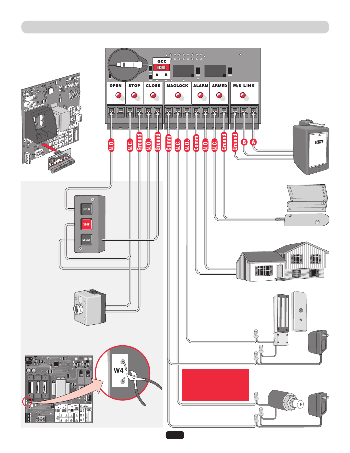
OMNI CONTROL™ BOARD CONNECTIONS
Purchased separately from Chamberlain Elite
®
.
NOTE: Cut jumper W4 wire for 3 button station or
stop button.
Stop
Button
Dry Contact
3 Button
Station
Dry Contact
Second
Operator
Proximity
Switch
12Vdc House Alarm
Maglock
Solenoid Lock
Relay Contact Rating
0.5 Amp - 125Vac
1 Amp - 24Vdc
NOTE: Refer to the
OmniControl™ board manual
for more specific information.
34
MAINTENANCE:
1. Disconnect power before servicing.
2. The gate area should be kept clean to insure proper operation.
3. Make sure the hinges are working smoothly and lubricated properly.
4. Make sure gate arm is greased properly.
5. Check gate reversing sensor. Check it monthly.
6. Check for proper synthetic oil level in the upper gear box (10W-30 weight synthetic oil).
7. Severe or high cycle usage will require more frequent maintenance checks.
8. Inspection and service should always be performed anytime a malfunction is observed or suspected.
9. When servicing, please do some “house cleaning” of the operator and the area around the operator. Pick up any debris in the area.
Clean the operator as needed.
10. It is suggested that while at the site voltage readings be taken at the operator. Using a Digital Voltmeter, verify that the incoming
voltage to the operator is within ten percent of the operators rating.
IMPORTANT SAFETY INSTRUCTIONS
To reduce the risk of SEVERE INJURY or DEATH:
1. READ AND FOLLOW ALL INSTRUCTIONS.
2. NEVER let children operate or play with gate controls.
Keep the remote control away from children.
3. ALWAYS keep people and objects away from the gate.
NO ONE SHOULD CROSS THE PATH OF THE MOVING
GATE.
4. Test the gate operator monthly. The gate MUST reverse
on contact with a rigid object or stop when an object
activates the non-contact sensors. After adjusting the
force or the limit of travel, retest the gate operator.
Failure to adjust and retest the gate operator properly
can increase the risk of INJURY or DEATH.
5. Use the emergency release ONLY when the gate is not
moving.
6. KEEP GATES PROPERLY MAINTAINED. Read the
owner’s manual. Have a qualified service person make
repairs to gate hardware.
7. The entrance is for vehicles ONLY. Pedestrians MUST
use separate entrance.
8. Disconnect ALL power BEFORE performing ANY
maintenance.
9. ALL maintenance MUST be performed by a
Chamberlain Elite professional.
10.
SAVE THESE INSTRUCTIONS.
Maintenance and Operation
35
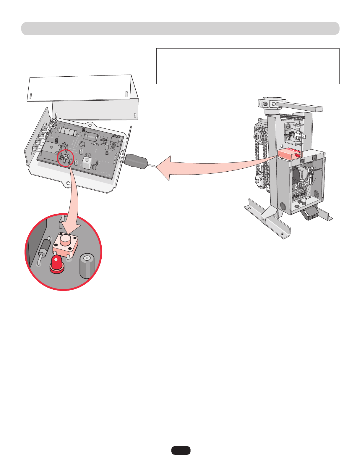
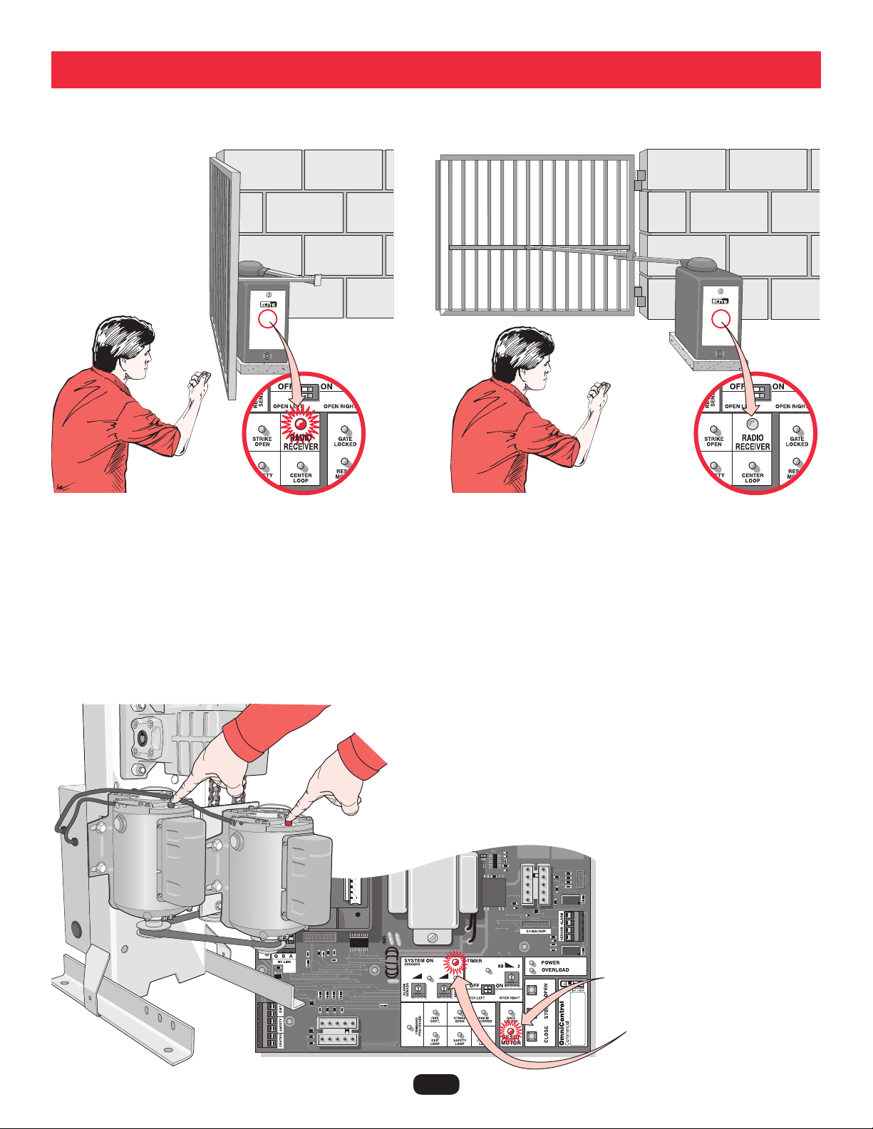
BUILT-IN RESET SWITCH
AUDIO ALARM
When the gate operator’s audio alarm (see below) has been tripped, the reset switch must be
pushed for the operator to function again.
The reset switch will shut off an activated audio alarm and reset the operator to function again.
If the audio alarm goes off, always check the gate area for:
• Obstructionsinthegatepath.
• Damagetothegateand/orgateoperator.
The operator arm or gate
is incorrectly installed.
Horizontal Level
Vertical
Level
The gate is TOO heavy.
An externally wired photoelectric sensor has been
triggered twice (photoelectric sensor blocked).
Gate hinges are too tight or broken and
the gate is not moving freely.
The gate hits the driveway, curb or other, and
gets stuck or bent in an awkward position.
The gate is moving and a car pushes the
gate.
A foreign object is on the gate frame while
the gate is moving.
Press the built-in reset switch to shut off alarm and reset operator (see above).
Incorrect
Incorrect
Pressing the reset switch will stop a moving gate during a
normal open/close cycle, like a stop button. The operator
does NOT need to be reset after doing this.
The alarm could be tripped when one of the following happens twice consecutively,
then the alarm will sound for 5 minutes or until the reset switch is pressed!
36
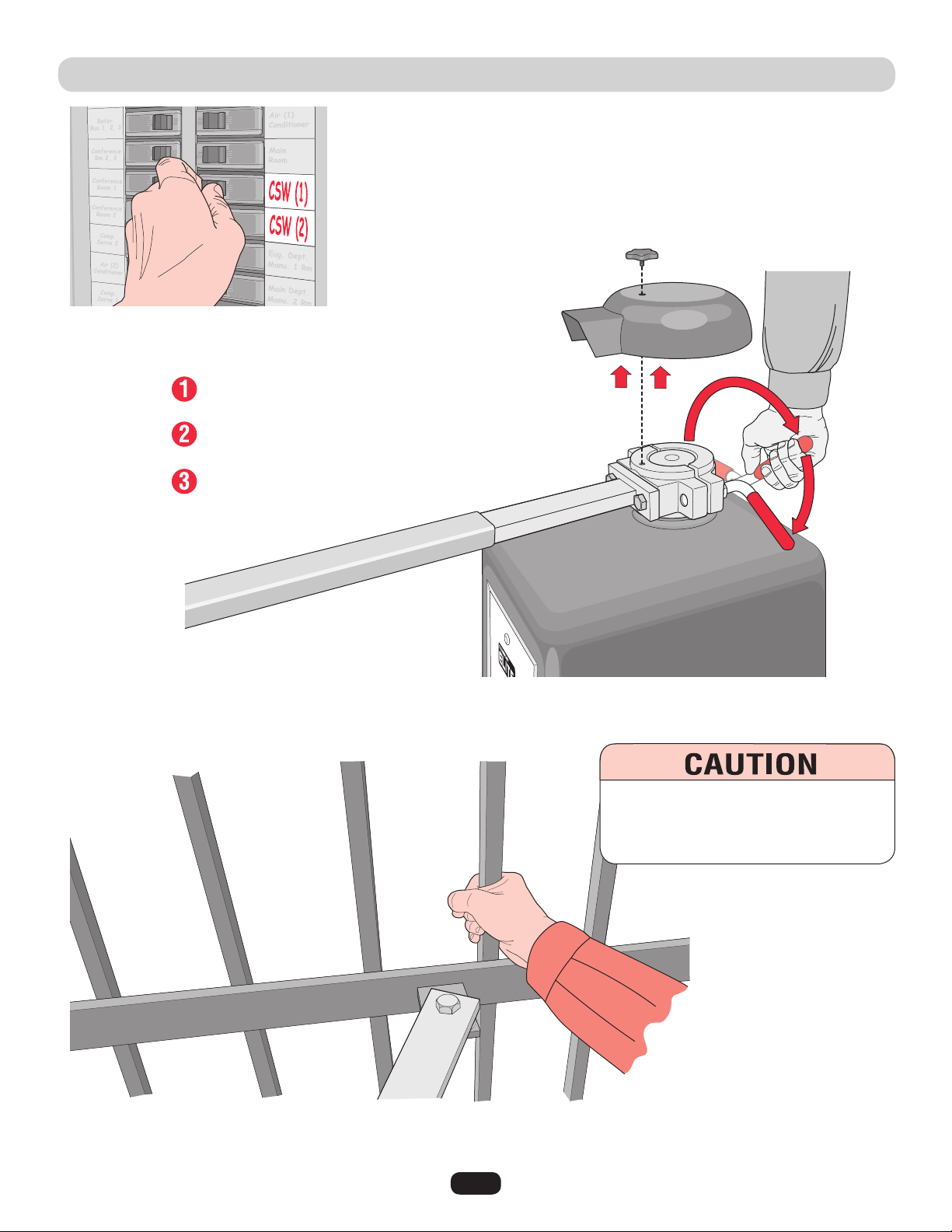
EMERGENCY MANUAL RELEASE
Tighten the red handle, replace the cover and knob when finished.
When the power is on again, the gate will readjust itself automatically.
Unscrew star knob.
Lift off cover.
Loosen red handle as shown.
Gate can now be manually moved.
NOTE: Use the dedicated breaker switch to disconnect power to the operator.
Grab the gate to move it.
To reduce the risk of SERIOUS INJURY:
DO NOT grab the operator arm to move the
gate or your fingers could get pinched.
37
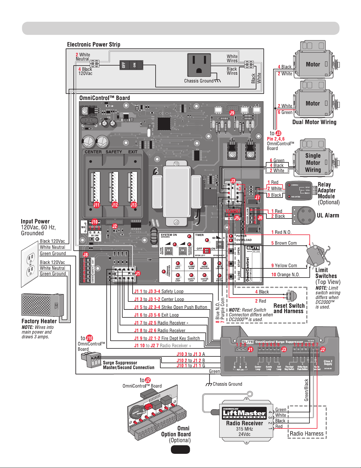
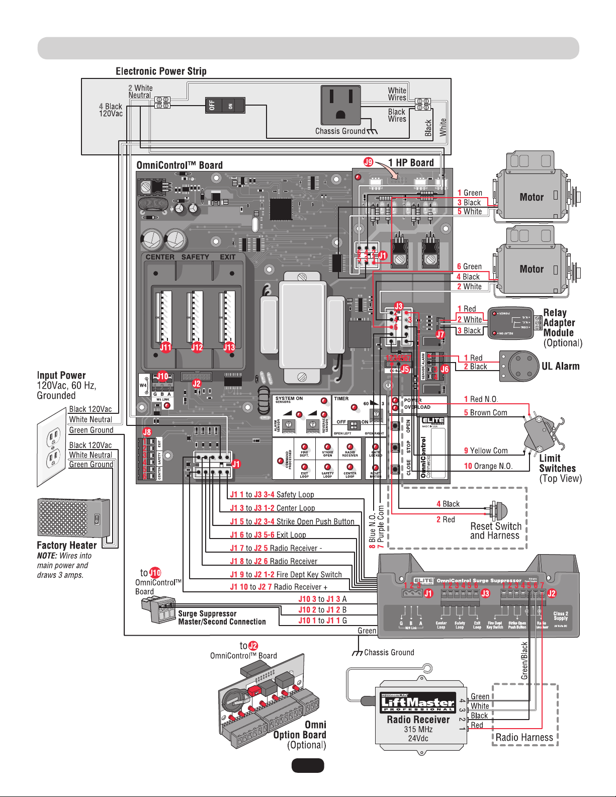
WIRING DIAGRAM • CSW200UL™ AND CSW200ULDM™
NOTE: See table on next page.
38
J1
J1
J1
J1
J1
J1
J1
J1
J1
J1
J2
J3
J3
J3
J3
J3
J3
J3
J3
J3
J3
J5
J5
J5
J5
J5
J5
J5
J6
J6
J6
J6
J7
J7
J7
J8
J8
J8
J8
J8
J8
J9
J10
J10
J10
J11
J12
J13
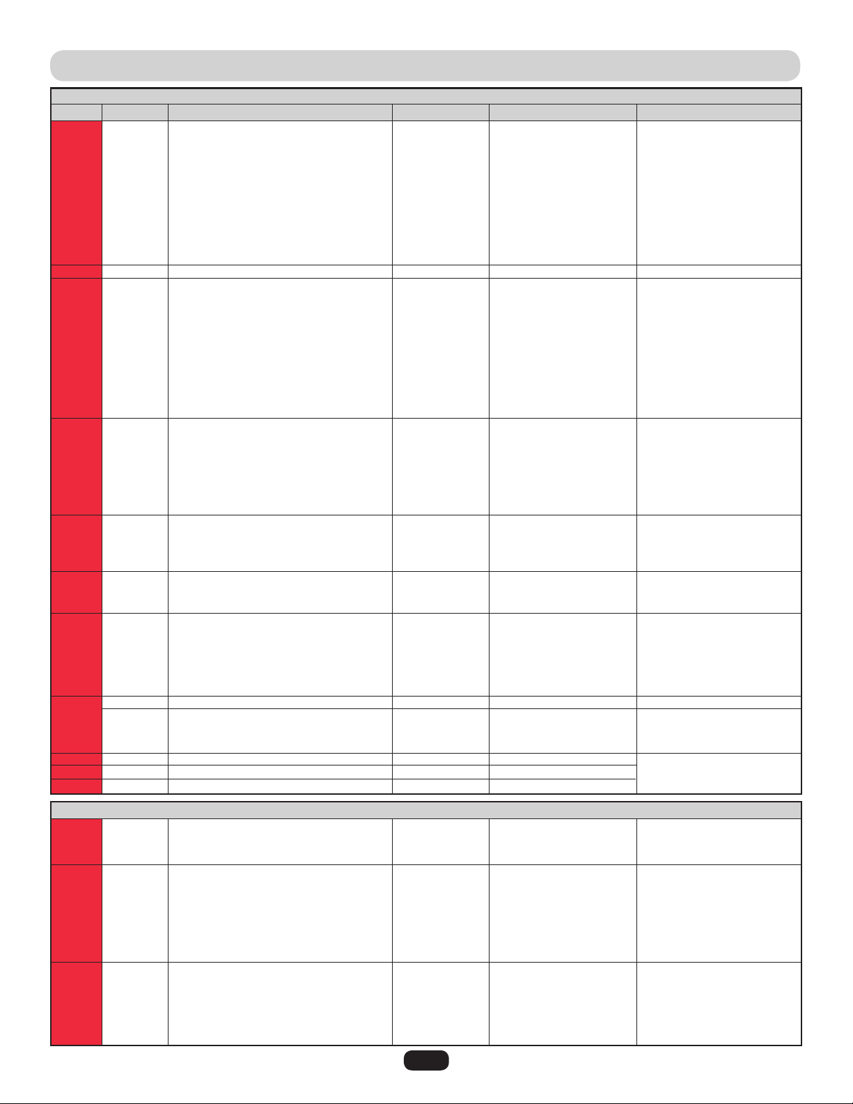
WIRING TABLE • CSW200UL™ AND CSW200ULDM™
J1
J1
J1
J2
J2
J2
J2
J2
J2
J2
J3
J3
J3
J3
J3
J3
1
2
3
4
5
6
7
8
9
10
10 Pins
1
2
3
4
5
6
7
8
9
10
1
2
3
4
5
6
7
1
2
3
4
1
2
3
1
2
3
4
5
6
16 Pins
1
2
3
10 Pins
10 Pins
10 Pins
1
2
3
1
2
3
4
5
6
7
1
2
3
4
5
6
Safety Loop
Input Power Neutral
Center Loop
Input Power 120Vac
Strike Open
Exit Loop
Radio Receiver –
Radio Receiver
Fire Dept Key Switch
Radio Receiver +
OmniControl™ Board
Limit Switch Red N.O.
Motor White
Normally Closed (No Wire)
Motor Black
Limit Switch Brown Com
Motor Green
Purple Com
Blue N.O.
Limit Switch Yellow Com
Limit Switch Orange N.O.
–
Reset Switch Red
–
Reset Switch Black
–
–
–
UL Alarm Red
UL Alarm Black
Photoelectric Sensor
Photoelectric Sensor
Relay Adapter Red
Relay Adapter White
Relay Adapter Black
Plug-In Exit Loop Wire
Plug-In Exit Loop Wire
Plug-In Safety Loop Wire
Plug-In Safety Loop Wire
Plug-In Center Loop Wire
Plug-In Center Loop Wire
1 HP Board
G M/S Link
B M/S Link
A M/S Link
Center Loop Detector
Safety Loop Detector
Exit Loop Detector
G M/S Link (G)
B M/S Link (B)
A M/S Link (A)
Fire Dept. Key Switch (7)
Fire Dept. Key Switch (8)
Strike Open Push Button (9)
Strike Open Push Button (10)
Radio Receiver – (11)
Radio Receiver (12)
Radio Receiver + (13)
Center External Loop Detector (1)
Center External Loop Detector (2)
Safety External Loop Detector (3)
Safety External Loop Detector (4)
Exit External Loop Detector (5)
Exit External Loop Detector (6)
In
In
In
In
In
In
In
In
In
Out
Out
Out
Out
In
Out
In
Out
In
In
In
In
In
In
In
In
In
In
In
Out
Out
In
In
In
In
In
In
In
In
In
In
In
–
In/Out
In/Out
In/Out
In
In
In
5 or 0Vdc
0V
5 or 0Vdc
120Vac
5 or 0Vdc
5 or 0Vdc
0V
0V
Dry
24Vdc
24Vdc
0Vdc
0V
5 or 0Vdc
120Vac
0V
120Vac
0V
5 or 0Vdc
0V
5 or 0Vdc
–
Dry
–
Dry
–
–
–
24Vdc
0Vdc
5 or 0Vdc
0V
5 or 0Vdc
0Vdc
0Vdc
2 to 10Vdc
2 to 10Vdc
2 to 10Vdc
2 to 10Vdc
2 to 10Vdc
2 to 10Vdc
–
0Vdc
5 or 0Vdc
5 or 0Vdc
5 or 0Vdc
5 or 0Vdc
5 or 0Vdc
0V
5 or 0Vdc
5 or 0Vdc
Dry
Dry
5 or 0Vdc
0V
0V
5 or 0Vdc
24Vdc
2 to 10Vdc
2 to 10Vdc
2 to 10Vdc
2 to 10Vdc
2 to 10Vdc
2 to 10Vdc
In/Out
In/Out
In/Out
In
In
In
In
In
In
Out
In
In
In
In
In
In
Not Used
OmniControl™ Board Input
Motor(s),
Limit Switches,
Maglock/Solenoid
Harness
External Loop Detector
Wires,
120Vac Power,
Radio Receiver,
Strike Open,
Key Switch
Harness
Radio Receiver,
Strike Open Push Button,
Fire Dept Key Switch
Inputs
External Loop
Detector Center,
Safety, Exit Wires
Input
Master/Second Link
Master/Second Link
Input
Plug-In Loop
Detector Inputs
Plug-In Loop
Detector Wires
Relay Adapter
Module Input
UL Alarm and
Photoelectric Sensors
Reset Switch
Input
J # Direction
OmniControl™ Surge Suppressor
OmniControl™ Board
Level (+/- 10%)J Pin # Input ConnectionSignal Type
NOTE: See diagram on previous page.
39
WIRING DIAGRAM • CSW200UL1HP™
NOTE: See table on next page.

40
J1
J1
J1
J1
J1
J1
J1
J1
J1
J1
J2
J3
J3
J3
J3
J3
J3
J3
J3
J3
J3
J5
J5
J5
J5
J5
J5
J5
J6
J6
J6
J6
J7
J7
J7
J8
J8
J8
J8
J8
J8
J9
J10
J10
J10
J11
J12
J13
WIRING TABLE • CSW200UL1HP™
J1
J1
J1
J2
J2
J2
J2
J2
J2
J2
J3
J3
J3
J3
J3
J3
1
2
3
4
5
6
7
8
9
10
10 Pins
1
2
3
4
5
6
7
8
9
10
1
2
3
4
5
6
7
1
2
3
4
1
2
3
1
2
3
4
5
6
16 Pins
1
2
3
10 Pins
10 Pins
10 Pins
1
2
3
1
2
3
4
5
6
7
1
2
3
4
5
6
J1
J1
J1
J1
J1
J1
1
2
3
4
5
6
Safety Loop
Input Power Neutral
Center Loop
Input Power 120Vac
Strike Open
Exit Loop
Radio Receiver –
Radio Receiver
Fire Dept Key Switch
Radio Receiver +
OmniControl™ Board
Limit Switch Red N.O.
Motor White
Normally Closed (No Wire)
Motor Black
Limit Switch Brown Com
Motor Green
Purple Com
Blue N.O.
Limit Switch Yellow Com
Limit Switch Orange N.O.
–
Reset Switch Red
–
Reset Switch Black
–
–
–
UL Alarm Red
UL Alarm Black
Photoelectric Sensor
Photoelectric Sensor
Relay Adapter Red
Relay Adapter White
Relay Adapter Black
Plug-In Exit Loop Wire
Plug-In Exit Loop Wire
Plug-In Safety Loop Wire
Plug-In Safety Loop Wire
Plug-In Center Loop Wire
Plug-In Center Loop Wire
1 HP Board
G M/S Link
B M/S Link
A M/S Link
Center Loop Detector
Safety Loop Detector
Exit Loop Detector
G M/S Link (G)
B M/S Link (B)
A M/S Link (A)
Fire Dept. Key Switch (7)
Fire Dept. Key Switch (8)
Strike Open Push Button (9)
Strike Open Push Button (10)
Radio Receiver – (11)
Radio Receiver (12)
Radio Receiver + (13)
Center External Loop Detector (1)
Center External Loop Detector (2)
Safety External Loop Detector (3)
Safety External Loop Detector (4)
Exit External Loop Detector (5)
Exit External Loop Detector (6)
Motor Green
-
Motor Black
Input Power Black
Motor White
Input Power White
In
In
In
In
In
In
In
In
In
Out
Out
Out
Out
In
Out
In
Out
In
In
In
In
In
In
In
In
In
In
In
Out
Out
In
In
In
In
In
In
In
In
In
In
In
Out
In/Out
In/Out
In/Out
In
In
In
5 or 0Vdc
0V
5 or 0Vdc
120Vac
5 or 0Vdc
5 or 0Vdc
0V
0V
Dry
24Vdc
24Vdc
0Vdc
0V
5 or 0Vdc
120Vac
0V
120Vac
0V
5 or 0Vdc
0V
5 or 0Vdc
–
Dry
–
Dry
–
–
–
24Vdc
0V
5 or 0Vdc
0V
5 or 0Vdc
0V
0V
2 to 10Vdc
2 to 10Vdc
2 to 10Vdc
2 to 10Vdc
2 to 10Vdc
2 to 10Vdc
5 or 0Vdc
0V
5 or 0Vdc
5 or 0Vdc
5 or 0Vdc
5 or 0Vdc
5 or 0Vdc
0V
5 or 0Vdc
5 or 0Vdc
Dry
Dry
5 or 0Vdc
0V
0V
5 or 0Vdc
24Vdc
2 to 10Vdc
2 to 10Vdc
2 to 10Vdc
2 to 10Vdc
2 to 10Vdc
2 to 10Vdc
120Vac
-
120Vac
120Vac
0V
0V
In/Out
In/Out
In/Out
In
In
In
In
In
In
Out
In
In
In
In
In
In
Out
-
Out
In
Out
In
1 HP Motors Board
OmniControl™ Board Input
Limit Switches,
Maglock/Solenoid
Harness
External Loop Detector
Wires,
120Vac Power,
Radio Receiver,
Strike Open,
Key Switch
Harness
Radio Receiver,
Strike Open Push Button,
Fire Dept Key Switch
Inputs
External Loop
Detector Center, Safety,
Exit Wires
Input
Master/Second Link
Master/Second Link
Input
2 Motors Output
Plug-In Loop Detector
Inputs
Plug-In Loop Detector
Wires
Relay Adapter Module
Input
UL Alarm and
Photoelectric Sensors
Reset Switch Input
J # Direction
OmniControl™ Surge Suppressor
OmniControl™ Board
1 HP Board
Level (+/- 10%)J Pin # Input ConnectionSignal Type
NOTE: See diagram on previous page.
41
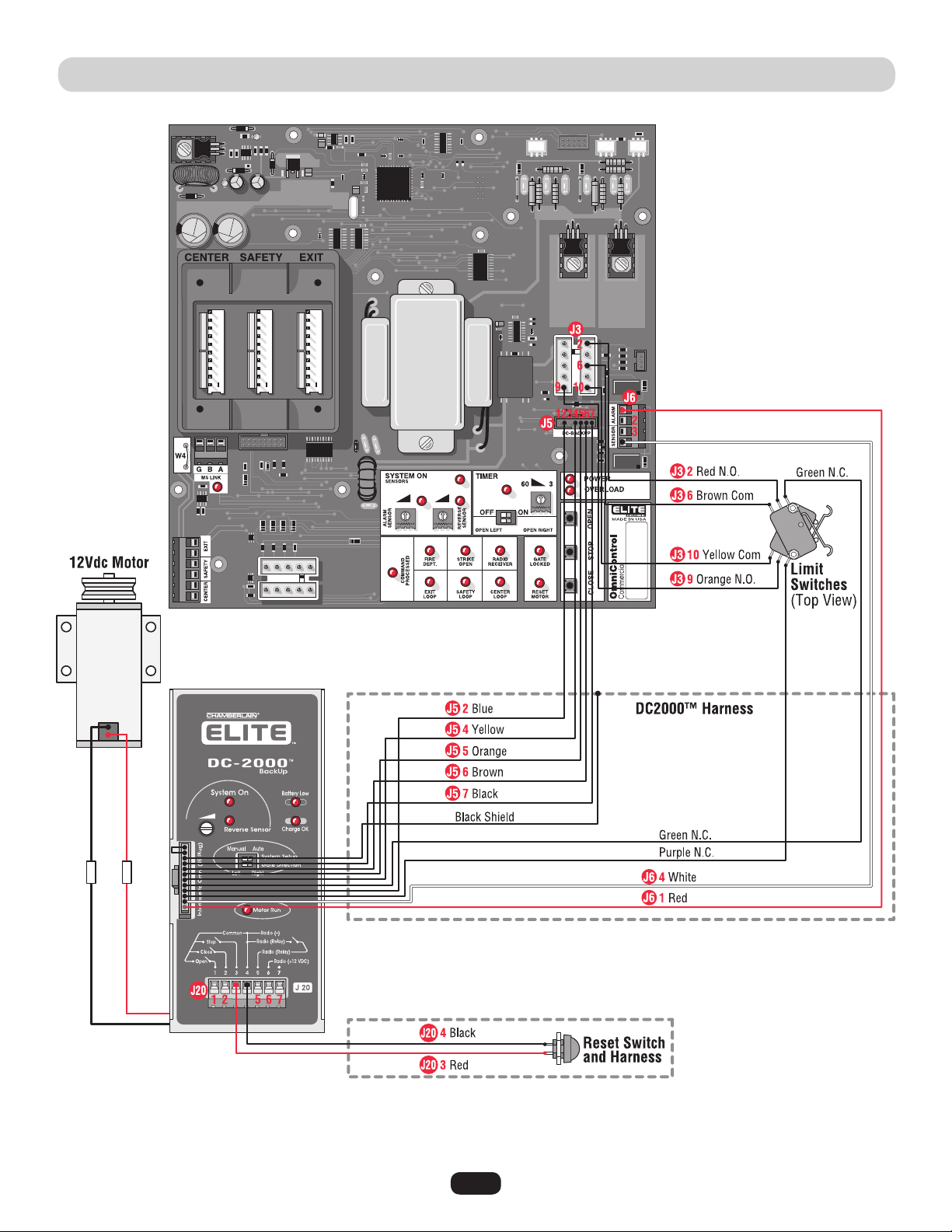
WIRING DIAGRAM • DC2000™ FOR SINGLE AND DM
NOTE: This diagram only shows
the DC2000™ wiring and all other
wiring not shown is the same as
the diagram on page 37.
The 1 HP models Can Not have the
DC2000™ battery backup system.
42
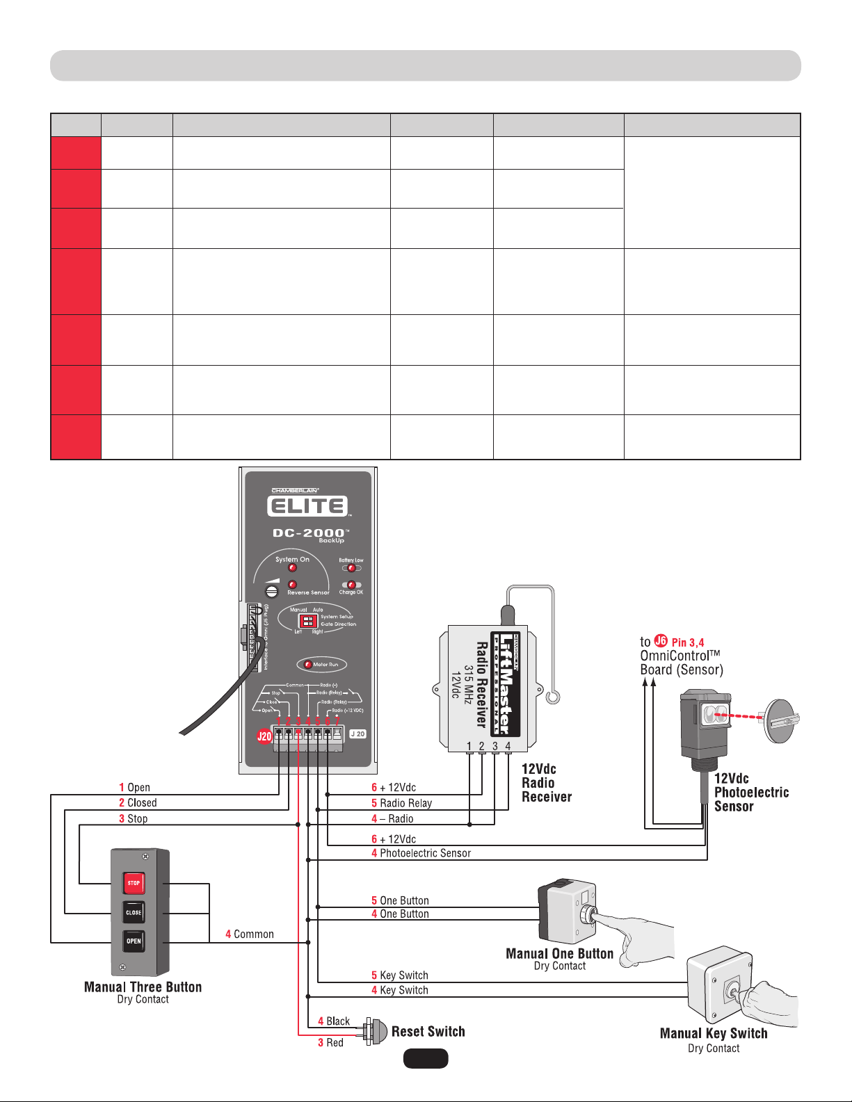
WIRING TABLE • DC2000™
J20
J20
J20
J20
J20
J20
J20
1
2
3
4
5
6
7
Open N.O.
Closed N.O.
Stop N.O.
Reset Switch
Common
Radio –
Radio Relay
Reset Switch
One Button
Key Switch
Radio Relay
Radio + 12Vdc
Photoelectric Sensor + 12Vdc
–
5 or 0Vdc
5 or 0Vdc
5 or 0Vdc
0V
0V
12 or 0Vdc
–
Out
Out
Out
Out
Out
Out
–
• Manual Three Button (Dry)
Reset Switch
• Manual One Button (Dry)
• Key Switch (Dry)
• Radio Receiver
• Reset Switch
• Manual One Button (Dry)
• Key Switch (Dry)
• Radio Receiver
• Radio Receiver 12Vdc
• Photoelectric Sensor 12Vdc
–
J # Direction Level (+/- 10%)J Pin # Input ConnectionSignal Type
NOTE: All devices wired to the DC2000™ MUST be dedicated to
it alone. Normal operation will be controlled by separate devices
wired to the OmniControl™ board and surge suppressor.
N.O.
N.O.
N.O.
43
Troubleshooting
1. Probable Cause: Stuck remote control button.
Solution: Unstick remote control button.
2. Probable Cause: The radio receiver has malfunctioned in the
“ON” position.
Solution: Cycle the power to the radio receiver.
1. Probable Cause: Remote control battery is dead.
Solution: Replace remote control battery.
2. Probable Cause: The radio receiver has malfunctioned in the
“OFF” position.
Solution: Cycle the power to the radio receiver. Remote control
will need to be reprogrammed, see page 30.
3. Probable Cause: Radio receiver’s signal is not getting to gate
operator.
Solution: Check wiring between receiver and surge suppressor.
4. Probable Cause: Remote is not programmed correctly.
Solution: Reprogram remote control, see page 30.
5. Probable Cause: Remote is not on the same frequency as the
radio receiver.
Solution: Verify that remote control frequency is 315 MHz.
6. Probable Cause: Blown surge suppressor.
Solution: Measure the resistance between pin 12 and 13 on the
surge suppressor (see page 16), if the circuit “closes” when
the radio receiver is transmitting, replace the surge suppressor.
The Gate Will Not Operate with Remote:
The radio receiver LED
on the control board remains “ON” when using the remote
control.
The Gate Will Not Operate with Remote:
The radio receiver LED
on the control board remains “OFF” when using the remote
control.
Resetting Motor(s)
NOTE: Press firmly to reset thermal breaker button(s).
Motor(s) need resetting when:
Reset Motor LED light flashes once,
System ON LED light flashes rapidly.

44
TROUBLESHOOTING (CONTINUED)
For technical support: 1-800-528-2806
1. Remove the short circuit condition at the
terminals.
2. Remove the defective loop detector.
3. Send the board to repair.
1. Reduce the accessories load from surge
suppressor terminal 13.
2. Verify your electrical power.
1. Reset the motor.
OR
2. Test the limit switches and wire connections,
fix the fault.
1. Remove the obstruction.
2. Turn the reverse sensor switch
counter-clockwise a little more and try again.
1. Remove the obstruction.
2. Turn the alarm sensor switch counter clockwise
a little more and try again.
1. This is a normal response of the gate operator. It
does not represent necessarily that there is a
problem.
1. This is a normal response of the gate operator. It
does not represent necessarily that there is a
problem. Check inputs for command.
1. Any re-new command will resume normal
operation. Check for obstructions.
1. Any re-new command will resume normal
operation but not a radio command. Check for
obstructions.
2. You can stop the alarm by using the built-in
reset button.
3. You can stop the alarm by using an optional
stop button.
1. Reset the loop detector (If you use Elite
®
Plug-in
Loop detectors, change the setting for sensitivity
and come back to your original setting.)
2. Verify and correct connections.
3. Set a different working frequency.
4. Decrease the sensitivity of the loop detector.
1. Short circuit at terminals 11 and 13.
2. Short circuit at any of the loop detectors in
the board.
3. Short circuit in the control board.
1. Excessive current draw at terminal 13.
2. Over-voltage at the 110 Vac line input.
1. Motor thermal fuse has popped-out
(Rapid Flashing).
OR
2. One limit switch is faulty (Rapid Flashing).
1. Gate has encountered an obstruction during
traveling.
2. Reverse sensor is extra sensitive.
1. Gate encountered an obstruction during
traveling.
2. Alarm sensor is extra sensitive.
1. There is a command hold active.
1. There is a command holding the gate open.
1. Gate has reopened because it encountered
an obstruction while closing.
1. Gate has encountered two consecutive
obstructions while trying to close or open.
1. The loop detector needs to be reset.
2. The wire loop has been disrupted.
3. The loop detector needs to work in a
different frequency.
4. The loop detector is too sensitive.
Probable CausesCondition Solution
Overload LED ON
and
Power LED OFF
Audio Alarm ON
Any Loop LED ON
and
No vehicle on the
sensing area
Overload LED ON
and
Power LED ON
Timer LED Blinking
and
Command Processed
LED Blinking
Timer LED Blinking,
Command Processed
LED Blinking
and
Reverse Sensor LED ON
System On LED
Flashing
Reverse Sensor LED ON
Alarm Sensor LED ON
Command Processed
LED ON
45
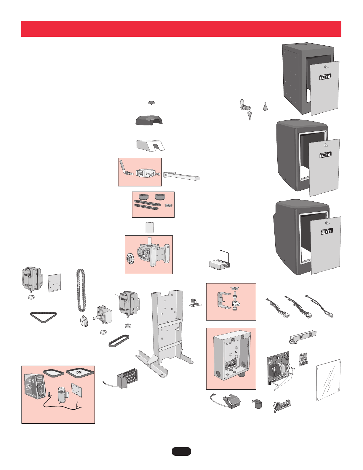
Q084
Q118
Q244
Q269
K45-50676
Q268
Q059
Q062
Q175
G6518CSW
Q018
Q018
Q025
Q025
Q523
Q045
Q046
Q183
Q212
Q220
Q027
Q044
Q216
312HM
Q029*
Q006
Q409
Q401
Q400E-1
Q520
Q521
Q407
Q408
Q410
Q404
K23-51142
NOTE: * Sold individually, 2 shown.
For part list, refer to next page.
Q061
Q057
Q166
Q210
ODC2000CSW
Q402
Q247
Repair Parts

46
OUR LARGE SERVICE ORGANIZATION SPANS AMERICA. INSTALLATION AND SERVICE INFORMATION
IS AS NEAR AS YOUR TELEPHONE. SIMPLY DIAL OUR TOLL FREE NUMBER:
1-800-528-2806
www.chamberlain.com
WHEN ORDERING REPAIR PARTS, ALWAYS GIVE THE FOLLOWING INFORMATION:
• PART NUMBER
• PART NAME
• MODEL NUMBER
Address orders to:
THE CHAMBERLAIN GROUP, INC.
Technical Support Group
6050 S. Country Club Road
Tucson, Arizona 85706
HOW TO ORDER REPAIR PARTS
312HM - 24V Radio Receiver
G6518CSW - Heater
K45-50676 - Star Knob
K23-51142 - Reset Button Assembly
Q006 - PC Board Nuts (Set)
Q018 - 1/2 HP Electric Motor
Q019 - Control Board Non UL (Not Shown)
Q025 - Motor Pulley (ID5/8)
Q027 - Motor Capacitor
Q029 - Limit Switch (One)
Q044 - Chain No. 50
Q045 - Drive Belt 1/2 HP 4L190
Q046 - Gear Reducer Pulley
Q059 - Output Arm Solid
Q062 - Cludge Cover - Stainless Steel
Q084 - Emergency Key Release
Q118 - Key for Access Door
Q175 - Belt UL DM/1 HP
Q183 - Sprocket (B50-16)
Q212 - Gear Reducer 40-30:1
Q216 - Output Shaft for 70 Reducer
Q220 - CSW200UL™ Chassis for 70 Reducer
Q244 - Cover - HD Polyethylene
Q247 - Cover - DM HD Polyethylene
Q268 - Cludge Cover - Plastic
Q269 - Stainless Steel Cover
Q400E-1 - Omni Main PCB (OmniControl™)
Q401 - Omni 1 Horsepower Board
Q404 - Omni Alarm
Q407 - Omni Motor Harness 1HP
Q408 - Electronic Power Strip
Q409 - Electronic Access Panel
Q410 - Surge Suppressor Terminal Block
Q520 - Omni Motor Harness
Q521 - Omni Motor Harness DM
Assembly Parts Number
NOTE:
REPAIR PART NAMES AND NUMBERS
Electronic Box Assembly - Q402
- Electronic Metal Box
- Surge Suppressor
- Audio Alarm
Power Back-Up Unit - ODC2000CSW
- Drive Belt DC CSW (DM)
- Back-Up Motor DC 12V
- Chassis DC Back-Up
- Hardware Kit for DC Back-Up
- Drive Belt DC CW 4L240
- Wire Harness DC-2000
- Pulley DC1000 1/2 ID
Assembly, limit Rack, CSW - Q165
- Limit Switch Bracket
- Limit Cam (Plastic Part)
Gear Box Assembly (Size 70) - Q210
- Sprocket
Sprocket and Chain Kit - Q057
- 1-1/8 inch dia. sprocket fits size 70 gear box
- 1 inch dia. sprocket fits size 60 gear box
- Sprocket #35
- Chain #35-72 Iinks
- Chain #35-68 Iinks
Cludge Assembly - Q061
- Arm Release Handle
- Output Shaft Cludge
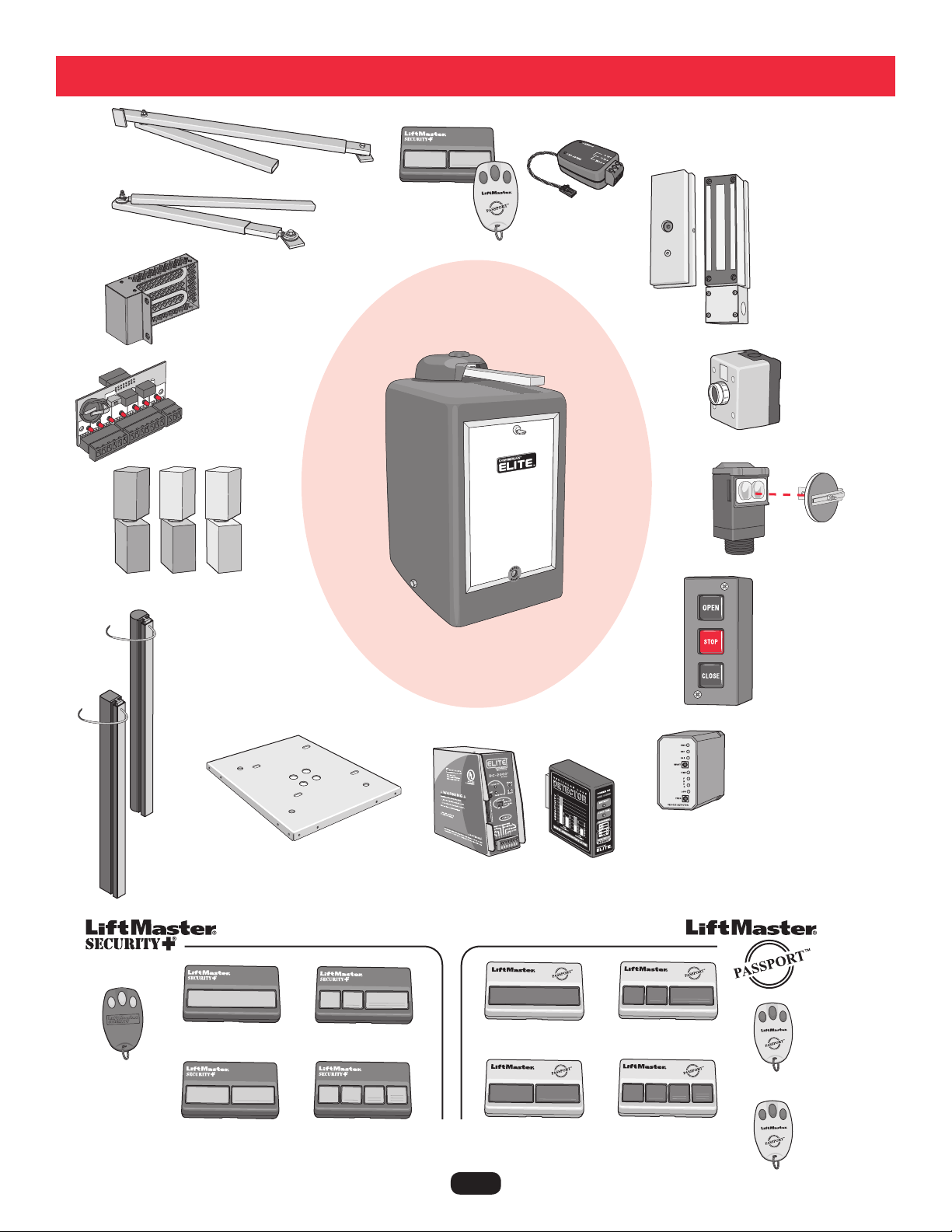
47
Standard Arm
Part # Q104
Swivel Arm
Part # Q103
OmniControl™ Board
Part # OOMNIEXB
Heater Kit
Part # G6518CSW
DC2000™ Kit
Part #
ODC2000CSW
Power Hinges
Stop Button
Part # AEXITP
UL Approved Round Sensing
Edge
Part # G65MGR20x
x= length (4, 5, 6 ,8 ft)
(e.g. G65MGR206 is 6 ft)
UL Approved Square
Sensing Edge
Part # G65MGS20x
x= length (4, 5, 6 ,8 ft)
(e.g. G65MGS204 is 4 ft)
110Vac External
Loop Detector
Part # A79
Magnetic Lock (Outdoor)
Part # MG1300
3-Button
Control Station
Part # 02-103
12Vdc Photoelectric
Sensor
Part #AOMRON
Remote Controls
Omni Relay Adapter
Part # Q400MAU
Accessories
Plug-In Loop Detector
Part # AELD
Mounting Plate
Part # MPEL
For more information about accessories:
www.chamberlain.com
Part # 371LM
Part # 372LM
Part # 373LM
Part # 374LM
Part # CPT13
Part # CPT23
Part # CPT33
Part # CPT43
Mini 3 Button
Part # 370LM
Mini 3 Button
Part # CPTK33
Mini 3 Button with
HID Prox, Sensor
Part # CPTK33PH

48
System Diagram

49
System Diagram

50
System Diagram

51
1. Owner and Installer must read all warnings and safety precautions.
2. Make sure concrete mounting pad is big enough and deep enough for operator.
3. Operator must be securely fastened to concrete pad or mounting plate.
4. Operator arm must be level and welded properly to gate.
5. Rectangular tubes on operator arm must be completely welded around.
6. When gate is pulled, No slippage of operator arm should occur.
7. Gate operator to be grounded to an earth ground rod within 3 feet of operator.
8. Verify that AC power is connected properly and Property Owner knows how to shut off power to operator.
9. Verify that the gate opens and closes as needed.
10. When gate hits object during operation, it must stop or reverse direction.
11. Know how to operate the emergency manual release.
12. Make sure that any pinch point or potential entrapment are guarded by means of safety devices or like.
13. Warning placards need to be permanently mounted on both sides of gate.
14. Test all additional equipment connected to operator.
15. Make sure all wire connections are securely fastened.
16. Review typical maintenance on operator.
17. Schedule periodic maintenance on operator by qualified service technician.
18. Inquire about Manufacturers “operator warranty.” (Warranty Card included with operator.)
19. Inquire about separate “installation warranty” with installer.
Installer Company Name, Address and Phone Number
Installation Checklist
Date Installed:

52
7 YEAR RESIDENTIAL / 5 YEAR COMMERCIAL CSW200UL™ LIMITED WARRANTY
The Chamberlain Group, Inc. (“Seller”) warrants to the first purchaser of this product, for the structure in which this product is
originally installed, that it is free from defect in materials and/or workmanship for a period of 7 year residential/ 5 year commercial
from the date of purchase [and that the CSW200UL™ is free from defect in materials and/or workmanship for a period of 7 year
residential/ 5 year commercial from the date of purchase]. The proper operation of this product is dependent on your compliance with
the instructions regarding installation, operation, maintenance and testing. Failure to comply strictly with those instructions will void
this limited warranty in its entirety.
If, during the limited warranty period, this product appears to contain a defect covered by this limited warranty, call 1-800-528-2806,
toll free, before dismantling this product. Then send this product, pre-paid and insured, to our service center for warranty repair. You
will be advised of shipping instructions when you call. Please include a brief description of the problem and a dated proof-of-purchase
receipt with any product returned for warranty repair. Products returned to Seller for warranty repair, which upon receipt by Seller are
confirmed to be defective and covered by this limited warranty, will be repaired or replaced (at Seller’s sole option) at no cost to you
and returned pre-paid. Defective parts will be repaired or replaced with new or factory-rebuilt parts at Seller’s sole option.
ALL IMPLIED WARRANTIES FOR THE PRODUCT, INCLUDING BUT NOT LIMITED TO ANY IMPLIED WARRANTIES OF MERCHANTABILITY
AND FITNESS FOR A PARTICULAR PURPOSE, ARE LIMITED IN DURATION TO THE 7 YEAR RESIDENTIAL/ 5 YEAR COMMERCIAL LIMITED
WARRANTY PERIOD SET FORTH ABOVE [EXCEPT THE IMPLIED WARRANTIES WITH RESPECT TO THE CSW200UL™, WHICH ARE
LIMITED IN DURATION TO THE 7 YEAR RESIDENTIAL/ 5 YEAR COMMERCIAL LIMITED WARRANTY PERIOD FOR THE CSW200UL™], AND
NO IMPLIED WARRANTIES WILL EXIST OR APPLY AFTER SUCH PERIOD. Some states do not allow limitations on how long an implied
warranty lasts, so the above limitation may not apply to you. THIS LIMITED WARRANTY DOES NOT COVER NON-DEFECT DAMAGE,
DAMAGE CAUSED BY IMPROPER INSTALLATION, OPERATION OR CARE (INCLUDING, BUT NOT LIMITED TO ABUSE, MISUSE, FAILURE
TO PROVIDE REASONABLE AND NECESSARY MAINTENANCE, UNAUTHORIZED REPAIRS OR ANY ALTERATIONS TO THIS PRODUCT),
LABOR CHARGES FOR REINSTALLING A REPAIRED OR REPLACED UNIT, OR REPLACEMENT OF BATTERIES.
THIS LIMITED WARRANTY DOES NOT COVER ANY PROBLEMS WITH, OR RELATING TO, THE GARAGE DOOR OR GARAGE DOOR
HARDWARE, INCLUDING BUT NOT LIMITED TO THE DOOR SPRINGS, DOOR ROLLERS, DOOR ALIGNMENT OR HINGES. THIS LIMITED
WARRANTY ALSO DOES NOT COVER ANY PROBLEMS CAUSED BY INTERFERENCE. ANY SERVICE CALL THAT DETERMINES THE
PROBLEM HAS BEEN CAUSED BY ANY OF THESE ITEMS COULD RESULT IN A FEE TO YOU.
UNDER NO CIRCUMSTANCES SHALL SELLER BE LIABLE FOR CONSEQUENTIAL, INCIDENTAL OR SPECIAL DAMAGES ARISING IN
CONNECTION WITH USE, OR INABILITY TO USE, THIS PRODUCT. IN NO EVENT SHALL SELLER’S LIABILITY FOR BREACH OF WARRANTY,
BREACH OF CONTRACT, NEGLIGENCE OR STRICT LIABILITY EXCEED THE COST OF THE PRODUCT COVERED HEREBY. NO PERSON IS
AUTHORIZED TO ASSUME FOR US ANY OTHER LIABILITY IN CONNECTION WITH THE SALE OF THIS PRODUCT.
Some states do not allow the exclusion or limitation of consequential, incidental or special damages, so the above limitation or
exclusion may not apply to you. This limited warranty gives you specific legal rights, and you may also have other rights which vary
from state to state.
Warranty Policy


01-50396G ® 2011, The Chamberlain Group, Inc. - All Rights Reserved