1
COMMERCIAL PROTECTOR SYSTEM
®
MODELS CPS-UN4 AND CPSUN4G
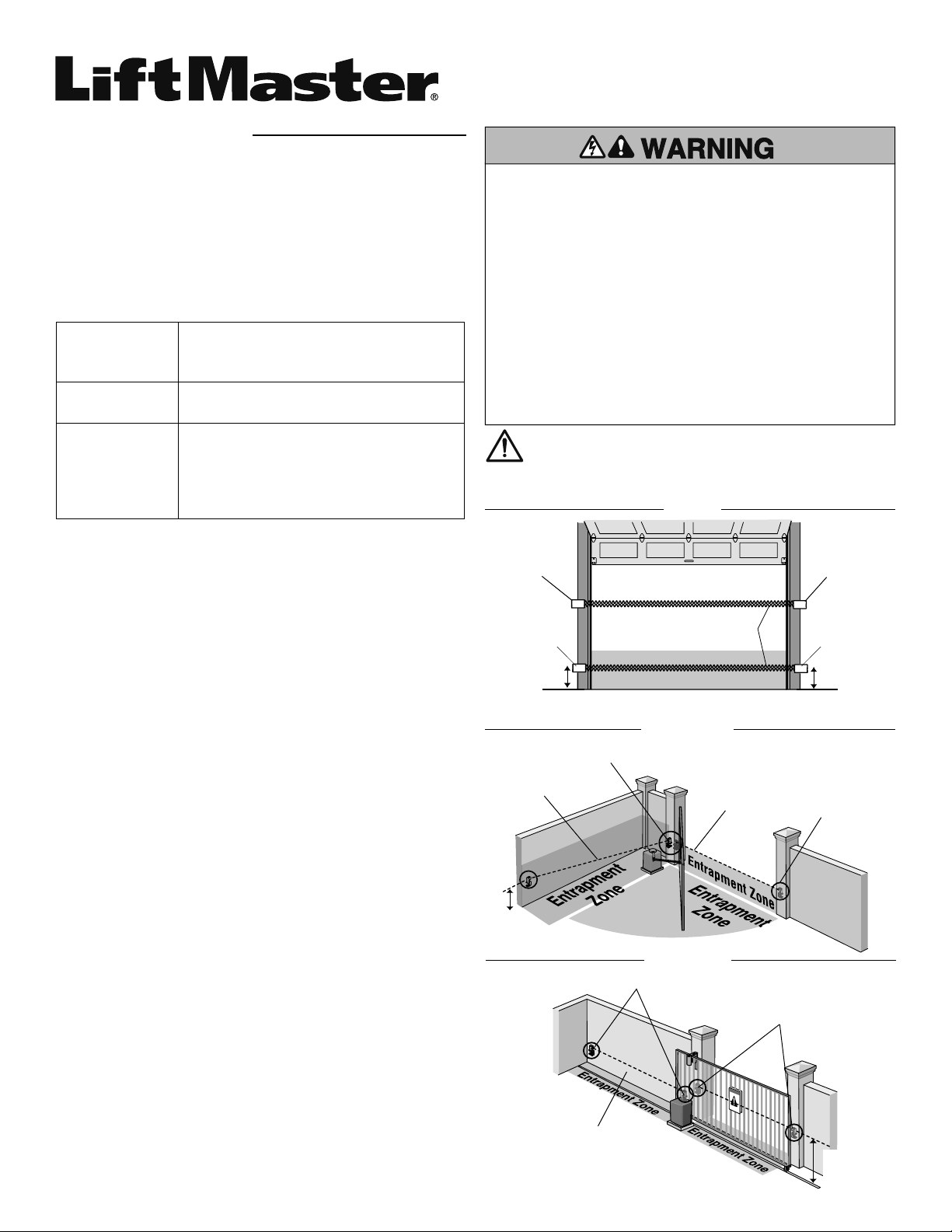
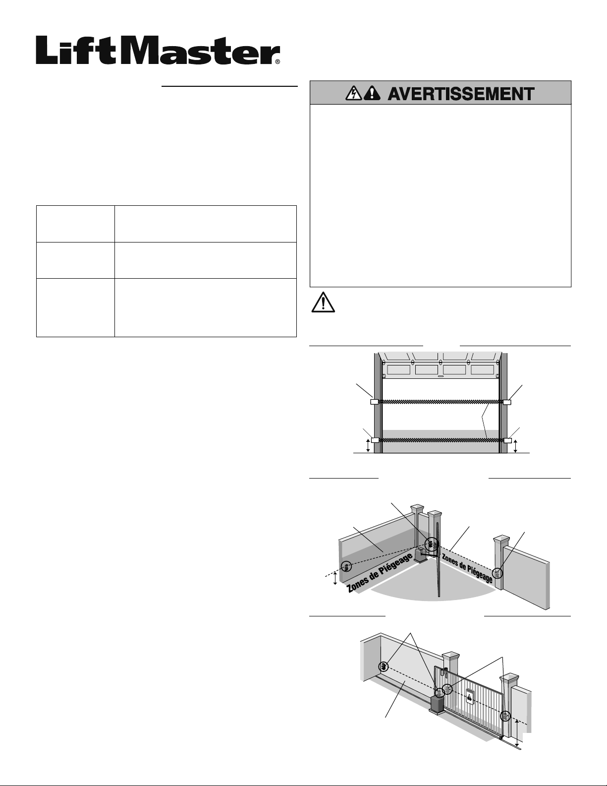
To prevent possible SERIOUS INJURY or DEATH from a closing
gate or door:
• Entrapment protection devices MUST be installed per the
operator owner's manual for each entrapment zone.
• Be sure to DISCONNECT POWER to the operator BEFORE
installing the photoelectric sensor.
• The gate or door MUST be in the fully opened or closed
position BEFORE installing the LiftMaster Monitored
Entrapment Protection device.
• Correctly connect and align the photoelectric sensor.
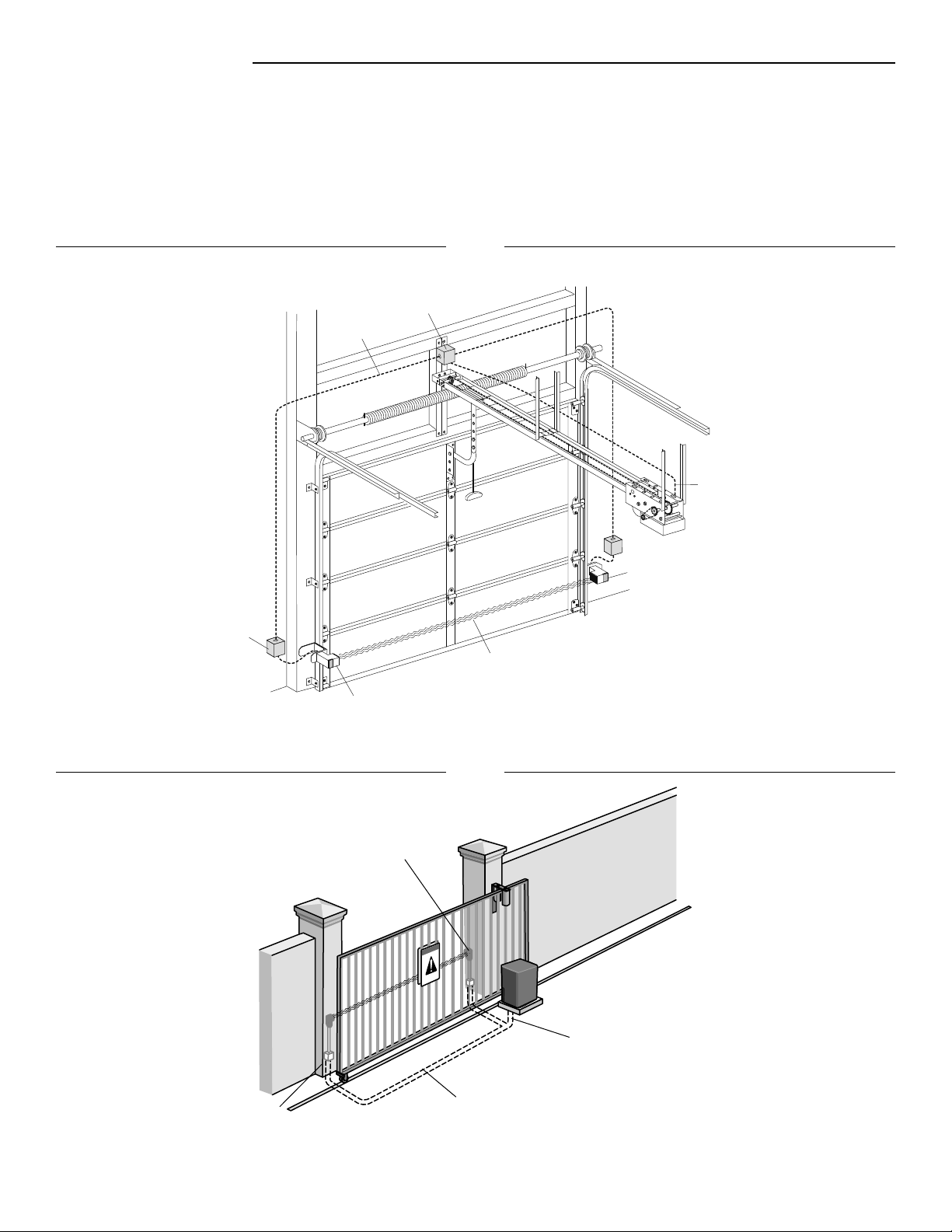
• For entrapment protection, install the photoelectric sensor
BEAM NO HIGHER than 6" (15 cm) above the fl oor for door
and 27.5" (69.8 cm) above grade for gate operators.
Photoelectric
Sensor
Photoelectric Sensor
27.5"
(69.8 cm)
max.
Facing the door from inside the garage
(installation procedures are the same for all door types).
Photoelectric
Sensor
6" (15 cm)
6" (15 cm)
Photoelectric
Sensor
Invisible Light Beam
Protection Area
Entrapment Zone
Photoelectric
Sensors
Photoelectric
Sensors
27.5"
(69.8 cm)
max.
Invisible Light Beam
Protection Area
Invisible Light Beam
Protection Area
Invisible Light Beam
Protection Area
IMPORTANT INFORMATION ABOUT THE
PHOTOELECTRIC SENSOR
Be sure power to the operator is disconnected.
When properly connected and aligned, the photoelectric sensor
will detect an obstruction in the path of its invisible light beam.
If an obstruction breaks the light beam while the door/gate is
closing, the operator will stop and typically reverse to the full open
position.
The sensors must be installed so that the emitter and receiver
sensors face each other across the entrapment zone and the beam
is no more than 6" (15 cm) above the fl oor for a commercial door
and no more than 27.5" (69.8 cm) above grade for a gate for
entrapment protection. Either can be installed on the left or right of
the entrapment zone as long as the sun never shines directly into
the receiver eye lens.
The brackets must be securely fastened to a solid surface such as
the wall framing. If installing in masonry construction, add a piece
of wood at each location to avoid drilling extra holes in masonry if
repositioning is necessary.
The invisible light beam path must be unobstructed. No part of
the gate or door (or door tracks, springs, hinges, rollers or other
hardware) may interrupt the beam while the door/gate is closing.
If it does, use a piece of wood to build out each sensor mounting
location to the minimum depth required for light beam clearance.
For commercial doors, additional photoelectric sensors may
be added at heights greater than 6" (15 cm) above the fl oor for
vehicle/property detection.
Photoelectric
Sensor
Photoelectric
Sensor
DOOR
SWING GATE
SLIDE GATE
LiftMaster
Commercial Door
Operators
Models FDC, FDCL, FDO, and LGE, Medium
Duty Logic, Logic 3, Logic 4, and Logic 5
LiftMaster Legacy
Gate Operators
Models CSL24V, CSW24V, RSL12V,
RSW12V, LA400, LA412 and LA500
LiftMaster 2016
UL 325 Gate
Operators
Models HCTDCU, LA400PKGU, LA412PKGU,
LA500PKGU, CSL24U, CSW24U, RSL12U,
RSW12U, CSW200501U, CSW200101U,
SL3000501U, SL3000101U, SL585U family,
and SL595U family
INTRODUCTION
APPLICATION
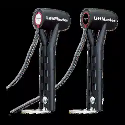
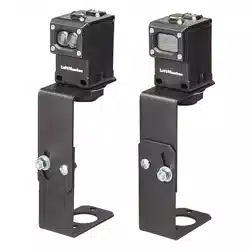
NOTE: The images throughout this manual are for reference and
your product may look different.
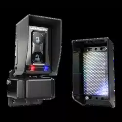
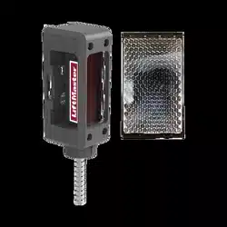
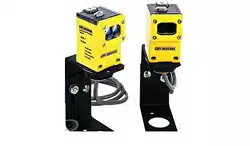
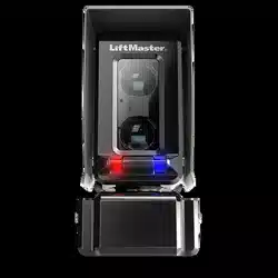
The Commercial Protector System is suitable for use in
applications where the photoelectric sensors will be exposed to
moisture. The CPS-UN4 and CPSUN4G are LiftMaster Monitored
Entrapment Protection (LMEP) devices and are compatible with
the following operators:
Vehicle/Property Detection
Monitored Entrapment Protection
WARNING: This product can expose you to chemicals including
lead, which are known to the State of California to cause cancer
or birth defects or other reproductive harm. For more information
go to www.P65Warnings.ca.gov
2
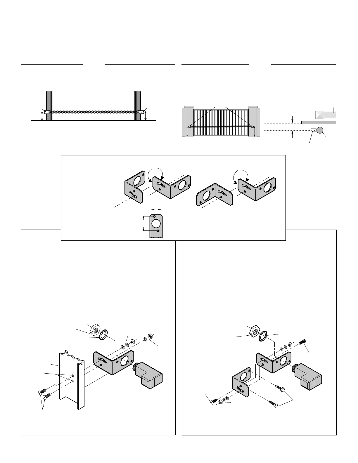
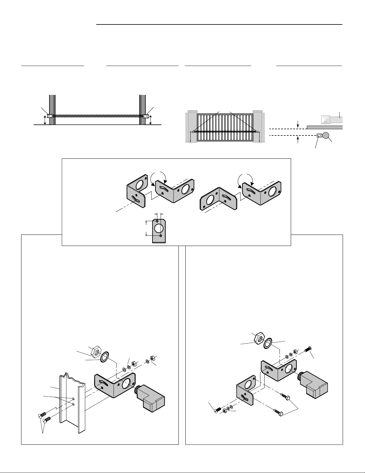
1. Fasten the bracket with the track bolts. NOTE: Always use
a fl at washer next to the radius slot. Putting track bolts in
slots will prevent brackets from pivoting.
2. Attach the bracket assembly to the wall with lag screws
(provided) or to the ground with concrete anchors (not
provided).
3. Insert the sensor into the brackets and fasten with the hex
mounting nut and lock washer.
1. Drill 1/4" holes in each track and securely fasten the bracket
with the track bolts. NOTE: Always use a fl at washer next to
the radius slot. To vertically attach to 2 x 4 wall stud it may
become necessary to rotate bracket to prevent wood from
splitting.
2. Insert the sensor into the bracket and fasten with the hex
mounting nut and lock washer.
INSTALLATION
ASSEMBLE AND MOUNT THE BRACKETS
Make sure the brackets are aligned so the photoelectric sensors will face each other across the entrapment zone. The brackets can be
mounted on the ground, door track, or wall.
Assemble to either side Flip one bracket and
assemble to either side
1/2" (1.3 cm)
Hole Spacing
2" (5.1 cm) Hole Spacing
BRACKET ASSEMBLY CONFIGURATIONS
1/4"-20x5/8"
Track Bolts
1/4" Flat Washer
1/4" Lock Washer
1/4" Hex Nut
1/4" Lock Washer
1/4"-20 Hex Nut
1/4"-20x5/8" Track Bolts
Lock Washer
Hex Mounting Nut
Hex Mounting Nut
Lock Washer
1/4" Flat Washer
1/4" Lock Washer
1/4" Hex Nut
1/4" Lock Washer
1/4"-20 Hex Nut
1/4"-20x5/8" Track Bolts
1/4" Drill
Holes
Door Track
Photoelectric
Sensor
Photoelectric
Sensor
5" (12.7 cm) max. gap
Edge of Gate Panel
Invisible Light Beam
Photoelectric
Sensor
Photoelectric Sensor
Mounting
Post
Wall or Fence
27.5" (69.8 cm) maximum
6"
(15 cm)
6"
(15 cm)
DOOR
Mount sensors no more than 6" (15 cm) above the fl oor and at a
width between 7'-45' (2.1 m - 13.7 m).
Mount within 5" (12.7 cm) of the moving gate panel with a
maximum height of 27.5" (69.8 cm) above grade (21" [53.3 cm]
is recommended) and at a width between 7'-45' (2.1 m - 13.7 m).
The recommended mounting location is on the inside of the gate.
Determine the
confi guration for your
brackets. The assembly
of the brackets will
vary depending on
your installation.
GROUND OR WALL INSTALLATION
DOOR TRACK INSTALLATION (FOR DOOR ONLY)
GATE
3
See
Con
Sensor Beam
Sensor Beam
6" (15 cm) max. ab
Invisible Light Beam
Protection Area
Liquid Tight
Conduit
Liquid Tight
Junction Box
d Tight
tion Box
Photoelectric Sensor
6" (15 cm) max. above the fl oor
Photoelectric Sensor Beam
6" (15 cm) max. above
the fl oor
Photoelectric Sensor Beam
27.5" (69.8 cm) maximum
above grade
Invisible Light Beam
Protection Area
Connect sensor wire to operator
(refer to Wiring section)
Liquid Tight
Conduit
Liquid
Tight
Junction
Box
INSTALLATION
CONDUIT CONNECTIONS
1. Disconnect power to the operator.
2. Use a liquid tight fi tting (1/2" [1.3 cm] trade size) with sealing washer to connect to sensors. The sensors are provided with 36"
(91.4 cm) long leads. LiftMaster recommends the use of a liquid tight junction box near each sensor to make the connection to the
sensor leads. Use rigid or fl exible liquid tight conduit (depending on local codes) from junction boxes to operator. IMPORTANT: Use a
minimum size 20 ga. copper wire for connection between the sensors and the operator.
Liquid Tight Conduit
Liquid Tight
Junction Box
Liquid Tight
Junction Box
DOOR
GATE
Connect sensor wire to operator
(refer to Wiring section)

4
^^^^
D14
COM INTRLK STOP
LED
OPE
N
CLOSE
TTC
LEARN
1
LMEP1
LMEP2
2 345 67
STOP CLOSE OPE
J2
1 2 3 4 5 6
7
13 14 15 16 17 18 19
R
T MID TTC
24VAC
24VAC
LMEP:
EDGE:
OPEN
CLOSE
MAS
COMMON
TIMER
DEFEAT
POWER
TIMER
ENABLE
23
3-PHASE
1-PHASE
Blue
Brown
WIRING
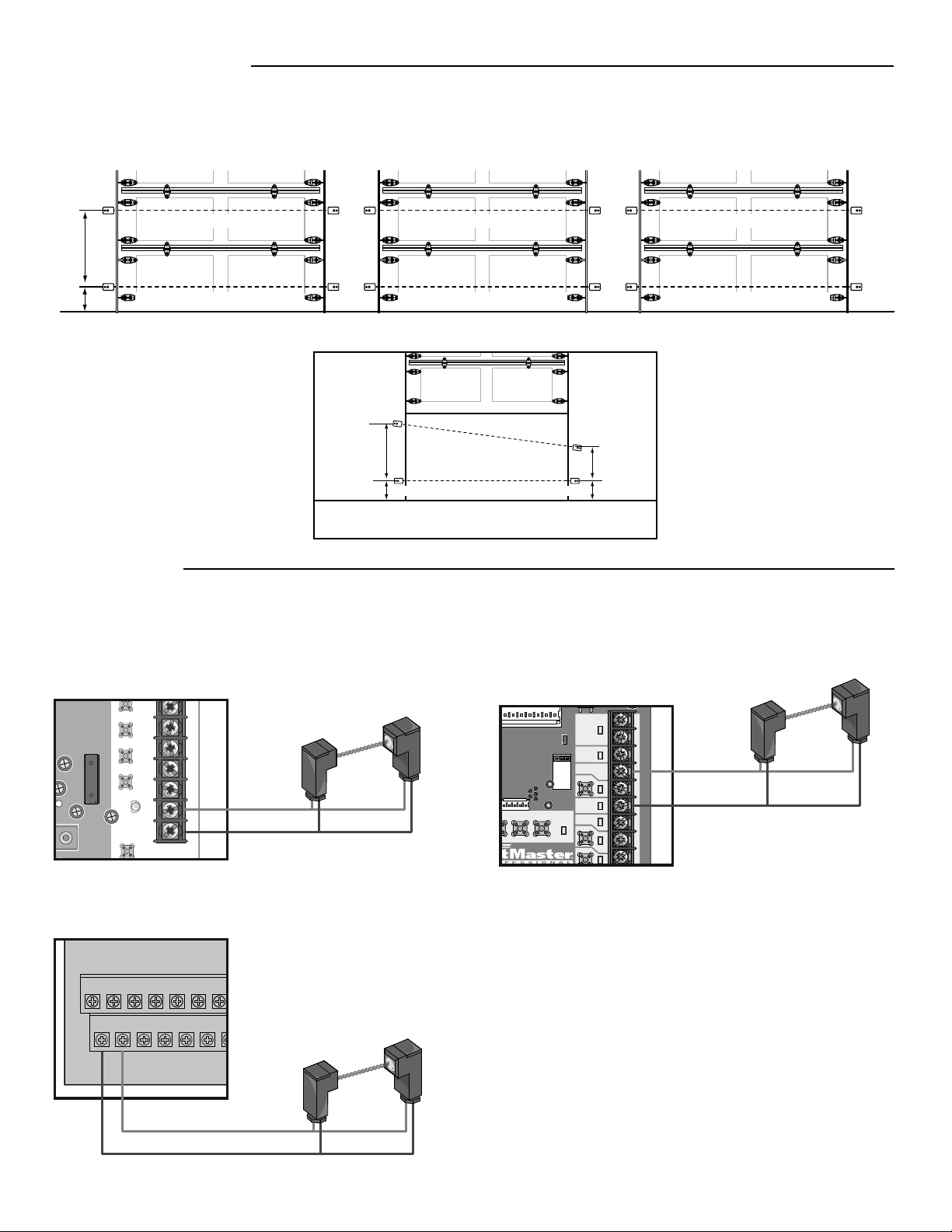
COMMERCIAL DOOR OPERATORS
MEDIUM DUTY LOGIC
Blue
Brown
Blue
Brown
LOGIC 3, 4, AND 5
MODELS FDC, FDCL, FDO, AND LGE
LOGIC BOARD
LOGIC BOARD
LOGIC BOARD
6" (15 cm) max. above fl oor
R E
E ER
R
DOOR #1 DOOR #2 DOOR #3
E
R R REE
Recommended installation for adjacent doors and more than one set of photoelectric sensors. For LOGIC 4 and LOGIC 5 Operators, a
CPS3CARD is required to wire a second set of monitored photoelectric sensors.
R = Receiver Sensor E = Emitter Sensor
24" (61 cm) min.
INSTALLATION
Vehicle/Property Detection
Monitored Entrapment Protection
Vehicle/Property Detection
Monitored Entrapment Protection
Vehicle/Property Detection
Monitored Entrapment Protection
Vehicle/Property Detection
Monitored Entrapment Protection
E
R
E
R
6" (15 cm) max. above fl oor
48" (122 cm)
min.
18" (46 cm)
min.

5
EYE
ONLY
EYE/
EDGE
EYE/
EDGE
COM
1
2
3
OPEN
CLOSE
TO M
A
BOA
R
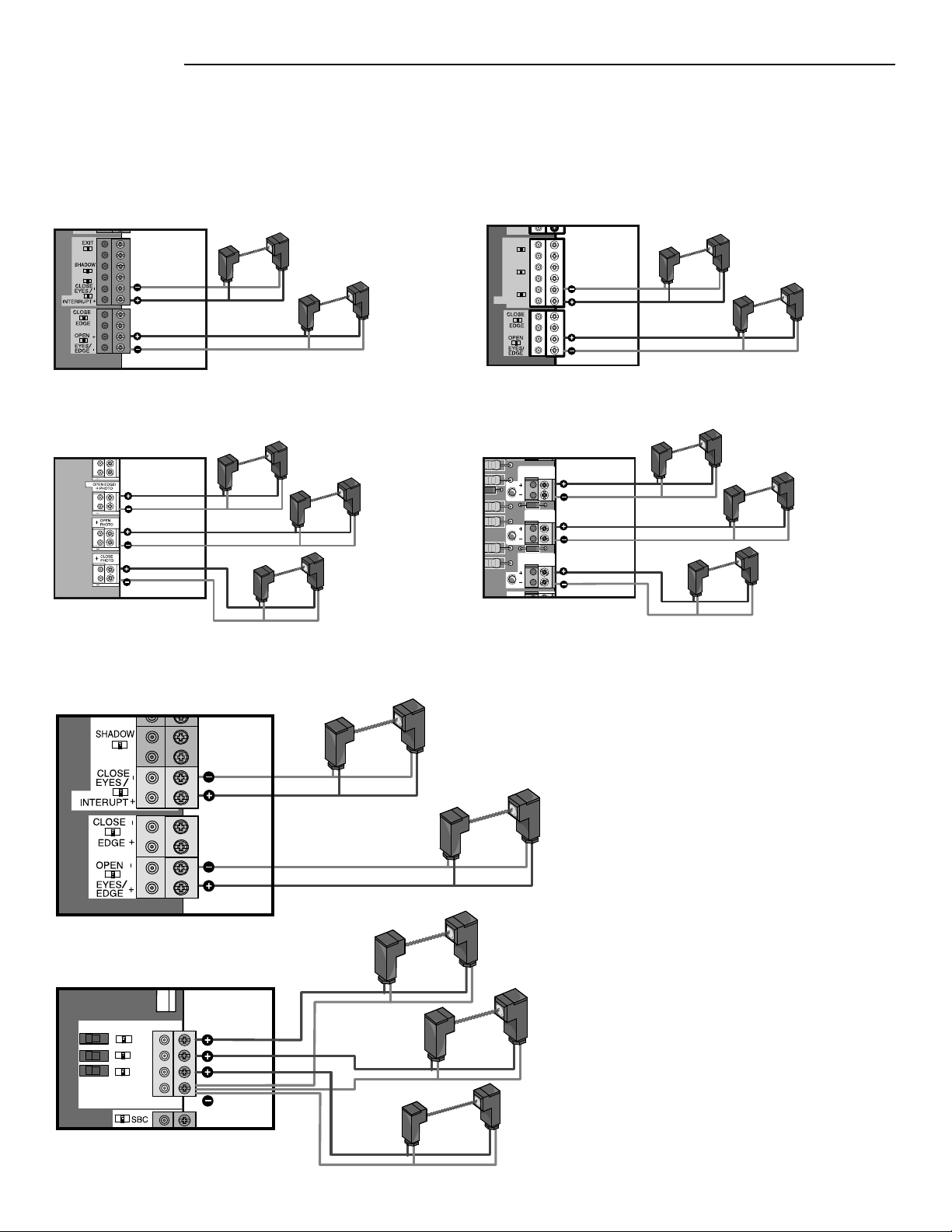
WIRING
2016 UL 325 GATE OPERATORS
The photoelectric sensors can be wired to function for either the open or close cycle depending on where they are wired on the control
board. Refer to your gate operator manual for more information.
CONTROL BOARD
EXPANSION BOARD
Brown
Blue
Brown
Blue
For OPEN cycle
For CLOSE cycle
Brown
Blue
Brown
Brown
For OPEN or CLOSE cycle, depending on
the OPEN CLOSE switch position.
For OPEN or CLOSE cycle, depending on
the OPEN CLOSE switch position.
For OPEN or CLOSE cycle, depending on
the OPEN CLOSE switch position.
LEGACY GATE OPERATORS
OPEN
EXIT
SHADOW
CLOSE
EYES/
INTERRUPT
- +
+ -
Z
22
R
91
R
94
R
92
R
93
OPEN EDGE/
PHOTO
OPEN
PHOTO
CLOSE
PHOTO
Z9
Z8
MODELS CSL24V AND CSW24V
CONTROL BOARD
MODELS LA412, RSW12V, AND RSL12V
CONTROL BOARD
MODEL LA500
CONTROL BOARD
MODEL LA400
CONTROL BOARD
For CLOSE cycle
For OPEN cycle
For CLOSE cycle
For OPEN cycle
For OPEN cycle
For OPEN cycle
For CLOSE cycle
For OPEN cycle
For OPEN cycle
For CLOSE cycle
Blue
Brown
Brown
Blue
Brown
Blue
Brown
Blue
Brown
Blue
Brown
Blue
Brown
Blue
Brown
Blue
Brown
Blue
Brown
Blue

TROUBLESHOOTING
If the emitter sensor and receiver sensor indicator lights do not glow steadily after installation, check for:
• Photoelectric sensor alignment
• Obstruction
• Power to the operator
• A short or broken wire
• Incorrect wiring between photoelectric sensors and the operator
If the receiver sensor indicator light is off or fl ashing (and the invisible light beam path is not obstructed), check alignment of the
sensors and/or for an open wire to the receiver sensor.
If the emitter sensor and receiver sensor indicator lights are both glowing steadily but interrupting the photoelectric sensors does
not cause the door/gate to reverse when closing, check both sensors to make sure one sensor is the emitter and the other is a
receiver sensor as indicated on the sensor housing.
NOTES:
• Direct sunlight to the receiver sensor may prevent the operator from closing even when both the emitter and receiver indicator lights
are illuminated. Swapping the position of the emitter and receiver sensors will resolve this issue.
• To avoid nuisance blockages from snow, install a hood over the photoelectric sensors to keep the snow from obstructing the lenses.
• Professional service is required if the operator closes the door/gate when the photoelectric sensors are obstructed.
• 2016 UL 325 gate operators have diagnostic codes related to entrapment protection devices. Refer to your gate operator manual or
wiring diagram for a list of troubleshooting diagnostic codes.
FOR SERVICE OR TO ORDER REPAIR PARTS DIAL:
1-800-528-2806
LiftMaster.com
WARRANTY
LiftMaster
®
warrants to the fi rst consumer purchaser of this product that it is free from defect in materials and/or workmanship for a
period of 1 year from the date of purchase.
TEST
1. Connect power to the operator.
2. Align the photoelectric sensors so the green LED on the emitter sensor and the yellow LED on the receiver sensor glow steadily.
3. Press the OPEN button to fully open the door/gate.
4. Press the CLOSE button to close the door/gate.
5. For doors: Obstruct the light beam while the door is closing. The door should stop and reverse.
For gates: Obstruct the light beam while the gate is opening or closing. If closing, the gate should stop and reverse to the full open
position. If opening, the gate should reverse for 4 seconds then stop.
The operator will not close if the indicator light in either sensor is not glowing steadily, alerting you to the fact that the sensor is
misaligned or obstructed.
1
DISPOSITIF PROTECTOR SYSTEM
®
À USAGE COMMERCIAL
MODÈLES CPS-UN4 ET CPSUN4G
Pour prévenir d’éventuelles BLESSURES GRAVES, voire
MORTELLES lorsqu’une porte ou un portail se ferme :
• Les dispositifs de protection contre le piégeage DOIVENT être
installés selon les instructions fournies dans le manuel du
propriétaire pour chaque zone de piégeage.
• S’assurer de DÉBRANCHER L’ALIMENTATION à l’actionneur
AVANT l’installation du capteur photoélectrique.
• Le portail DOIT être complètement ouvert ou complètement
fermé AVANT d’installer le dispositif de protection contre le
piégeage LiftMaster avec surveillance.
• Connecter et aligner correctement les capteurs photoélectriques.
• Installer le capteur photoélectrique afi n que son faisceau
se trouve à une hauteur NE DÉPASSANT PAS 15 cm (6 po)
au-dessus du sol pour les portes de garage et 27,5 po (69,8 cm)
pour les actionneurs de portail.
ATTENTION
AVERTISSEMENT
AVERTISSEMENT
AVERTISSEMENT
Zones de Piégeage
Zones de Piégeage
Capteur
photoélectrique
Capteur photoélectrique
Écart max.
de 69,8 cm
(27,5 po)
En faisant face à la porte de l’intérieur du garage (les directives
d’installation sont les mêmes pour tous les types de porte).
Capteur
photoélectrique
15 cm (6 po)
15 cm (6 po)
Capteur
photoélectrique
Zone de protection du
faisceau de lumière invisible
Zone de piégeage
Zones de Piégeage
Capteur
photoélectriqu
Écart max.
de 69,8 cm
(27,5 po)
Zone de protection du
faisceau de lumière
invisible
Zone de protection
du faisceau de
lumière invisible
Zone de protection
du faisceau de
lumière invisible
IMPORTANTE INFORMATION AU SUJET DU
CAPTEUR PHOTOÉLECTRIQUE
Vérifi er que l’alimentation électrique de l’actionneur est
débranchée.
Lorsqu'ils sont correctement connectés et alignés, les capteurs
photoélectriques détecteront un obstacle sur le passage de son
faisceau de lumière invisible. Si un obstacle entre dans le rayon
du faisceau pendant que la porte/le portail se ferme, l’actionneur
s’arrêtera et inversera la course du portail ou de la porte pour revenir
en position complètement ouverte.
Les capteurs de l’émetteur et du récepteur doivent être installés de
manière à se faire face de chaque côté de la zone de piégeage. Le
faisceau de détection ne doit pas être à une hauteur de plus de 15cm
(6po) du sol pour une porte commerciale et de plus de 69,8cm
(27,5po) pour une barrière pour assurer une protection contre le
piégeage. L’un ou l’autre dispositif peut être installé à gauche ou à
droite de la zone de piégeage à condition que le soleil n’éclaire jamais
directement dans la cellule photoélectrique du récepteur.
Les supports doivent être bien vissés à une surface solide comme
la charpente d’un mur. Si la pose se fait dans une construction en
maçonnerie, ajouter un morceau de bois à chaque endroit pour
éviter de percer des trous supplémentaires dans la maçonnerie si un
repositionnement est nécessaire.
Il ne doit y avoir aucun obstacle sur le parcours du faisceau de lumière
invisible. Aucune partie du portail ou de la porte de garage (ni les
guides, les ressorts, les charnières, les rouleaux ou autres fi xations)
ne doit interrompre le faisceau pendant que la porte/le portail se
ferme. Si le faisceau est bloqué de quelque façon que ce soit, utiliser
un morceau de bois pour surélever chaque emplacement de montage
des capteurs en laissant la profondeur minimale requise pour assurer
le dégagement du faisceau de lumière.
En ce qui concerne les portes commerciales, des capteurs à cellule
photoélectrique supplémentaires peuvent être ajoutés à des hauteurs
dépassant 15cm (6po) du sol pour la détection des véhicules/de la
propriété.
Capteur
photoélectrique
Capteur
photoélectrique
PORTE
PORTAIL À ARTICULATION
PORTAIL À GLISSIÈRE
Actionneurs de
porte commerciale
LiftMaster
Modèles FDC, FDCL, FDO et LGE, Logique de
service moyen, Logic 3, Logic 4 et Logic 5
Anciens
actionneurs de
barrière LiftMaster
Modèles CSL24V, CSW24V, RSL12V,
RSW12V, LA400, LA412 et LA500
Actionneurs de
barrière LiftMaster
2016 UL 325
Modèles HCTDCU, LA400PKGU, LA412PKGU,
LA500PKGU, CSL24U, CSW24U, RSL12U,
RSW12U, CSW200501U, CSW200101U,
SL3000501U, SL3000101U, gamme SL585U
et gamme SL595U
INTRODUCTION
APPLICATION
REMARQUE : Les illustrations de ce manuel ne sont fournies qu’à titre
de référence; votre produit peut avoir une apparence différente.
Le dispositif commercial Protector System convient aux applications
pour lesquelles les capteurs à cellule photoélectrique seront exposés
à l’humidité. Les modèles CPS-UN4 et CPSUN4G sont des dispositifs
surveillés de protection contre le piégeage LiftMaster compatibles
avec les actionneurs suivants :
Détection de véhicules/de la propriété
Protection surveillée contre le piégeage
Capteur
photoélectrique
AVERTISSEMENT : Ce produit peut vous exposer à des produits
chimiques comme le plomb, reconnu par l’État de la Californie
comme cause de cancers, d’anomalies congénitales et d’autres
problèmes liés à la reproduction. Pour plus d’informations,
visitez www.P65Warnings.ca.gov
2
1. Fixer le support à l’aide des boulons de guide. REMARQUE :
Se servir toujours d’une rondelle plate à côté de la fente
radiale. La pose de boulons de guide dans les fentes
empêchera les supports de pivoter.
2. Fixer l’ensemble des supports au mur à l’aide des tire-fond
(fournis) ou au sol à l’aide des ancrages en béton (non
fournis).
3. Insérer le capteur dans les supports et serrer à l’aide de l’écrou
de montage hexagonal et d’une rondelle de blocage.
1. Percer des trous de 1/4 po dans chaque guide et fi xer
solidement au support à l’aide des boulons de guide.
REMARQUE : Se servir toujours d’une rondelle plate à côté de
la fente radiale. Pour fi xer à la verticale à un poteau mural de
5 cm x 10 cm (2 po x 4 po), il peut être nécessaire de tourner
le support pour empêcher le bois de fendre.
2. Insérer le capteur dans le support et serrer à l’aide de l’écrou
de montage hexagonal et d’une rondelle de blocage.
INSTALLATION
ASSEMBLER ET MONTER LES SUPPORTS
S’assurer que les supports sont alignés de sorte que les capteurs photoélectriques se fassent face de chaque côté de la zone de piégeage. Les
supports peuvent être montés sur le sol, les guides de porte ou au mur.
Assembler d’un côté ou de l’autre
Retourner un support et
assembler de l’autre côté
Espacement du trou
de 1,3 cm (1/2 po)
Espacement du trou de
5,1 cm (2 po)
CONFIGURATIONS D’ASSEMBLAGE DES SUPPORTS
Écrou de montage
hexagonal
Rondelle de blocage
Rondelle plate
de 1/4 po
Rondelle de blocage
de 1/4 po
Écrou hexagonal
de 1/4 po
Rondelle de
blocage de 1/4 po
Écrou hexagonal
de 1/4 po - 20
Boulons de guide de 1/4 po-20x5/8 po
Trous de
perçage de
1/4 po
Guide de
porte
Capteur
photoélectrique
Bord ou panneau du portail
Faisceau de lumière
invisible
Capteur
photoélectrique
Capteur photoélectrique
Pilier de
montage
Mur ou clôture
Écart max. de 69,8 cm (27,5 po)
15 cm
(6 po)
15 cm
(6 po)
PORTE
Monter les capteurs à une distance ne dépassant pas 15 cm (6 po) du
sol et à une distance de 2,1 à 13,7 m entre eux (7 à 45 pi).
Monter à une distance de 12,7 cm (5 po) du panneau du portail en
déplacement, à une hauteur maximale de 69,8 cm (27,5 po)
au-dessus du sol (53,3 cm [21 po] est la hauteur recommandée) et à
une largeur de 2,1 m à 13,7 m (7 à 45 pi). L’emplacement de montage
recommandé se trouve à l’intérieur du portail.
Déterminer la
confi guration de vos
supports. L’assemblage
des supports variera
en fonction de votre
installation.
INSTALLATION AU SOL OU AU MUR
INSTALLATION DU GUIDE DE PORTE
(POUR PORTE DE GARAGE UNIQUEMENT)
PORTAIL
Boulons de guide de
1/4 po-20x5/8 po
Rondelle plate
de 1/4 po
Rondelle de blocage
de 1/4 po
Écrou hexagonal
de 1/4 po
Rondelle de blocage
de 1/4 po
Écrou hexagonal
de 1/4 po - 20
Boulons de guide de 1/4
po-20x5/8 po
Rondelle de blocage
Écrou de montage
hexagonal
Capteur
photoélectrique
Écart max. de 12,7 cm (5 po)

3
See
Con
Sensor Beam
Sensor Beam
6" (15 cm) max. ab
Invisible Light Beam
Protection Area
Liquid Tight
Conduit
Liquid Tight
Junction Box
d Tight
tion Box
Faisceau du capteur à
cellule photoélectrique à
69,8cm (27,5po) maximum
au-dessus du sol
Connecter le fi l du capteur à
l’actionneur (se reporter à la
section Câblage)
INSTALLATION
CONNEXIONS DES CONDUITES
1. Déconnecter l’alimentation de l’actionneur.
2.
Se servir d’un raccord étanche aux liquides (commercial de 1.3 cm [1/2 po]) avec une rondelle d’étanchéité pour connecter les capteurs. Les
capteurs sont fournis avec des fi ls d’alimentation de 91,4 cm (36 po) de long. Nous recommandons l’utilisation d’une boîte de connexion
étanche aux liquides à proximité de chaque capteur pour raccorder les fi ls d’alimentation des capteurs. Se servir d’une conduite rigide ou
souple étanche aux liquides (selon les codes locaux en vigueur) des boîtes de connexion à l’actionneur.
IMPORTANTE : Se servir d’un fi l de
cuivre de calibre 20 au minimum pour raccorder les capteurs à l’actionneur.
PORTE
PORTAIL
Connecter le fi l du capteur à
l’actionneur (se reporter à la
section Câblage)
Capteur photoélectrique
15 cm (6 po) max. au-dessus
du sol
Zone de protection du
faisceau de lumière invisible
Conduite
étanche aux
liquides
Conduite étanche
aux liquides
Boîte de
connexion
étanche aux
liquides
Boîte de
connexion étanche
aux liquides
Boîte de
connexion
étanche
aux
liquides
Faisceau du capteur à
cellule photoélectrique à
15 cm (6 po) maximum
au-dessus du sol
4
15 cm (6 po) max. au-dessus du sol
R E
E ER
R
E
R R REE
R = Capteur du récepteur E = Capteur de l’émetteur
61cm (24po) MIN.
Détection de véhicules/de la propriété
Protection surveillée contre le piégeage
Détection de véhicules/de la propriété
Protection surveillée contre le piégeage
Détection de véhicules/de la propriété
Protection surveillée contre le piégeage
Détection de véhicules/de la propriété
Protection surveillée contre le piégeage
E
R
E
R
15 cm (6 po) max. au-dessus du sol
122cm
(48po) MIN.
46cm
(18po)
MIN.
^^^^
D14
COM INTRLK STOP
LED
OPE
N
CLOSE
TTC
LEARN
1
LMEP1 LMEP2
2 345 67
STOP CLOSE OPE
J2
1 2 3 4 5 6
7
13 14 15 16 17 18 19
R
T MID TTC
24VAC
24VAC
LMEP:
EDGE:
OPEN
CLOSE
MAS
COMMON
TIMER
DEFEAT
POWER
TIMER
ENABLE
23
3-PHASE
1-PHASE
Bleu
Brun
CÂBLAGE
ACTIONNEURS DE PORTE COMMERCIAUX
LOGIQUE DE GAMME INTERMÉDIAIRE
Bleu
Brun
Bleu
Brun
LOGIC 3, 4, ET 5
MODÈLES FDC, FDCL, FDO ET LGE
CARTE LOGIQUE
CARTE LOGIQUE
CARTE LOGIQUE
Installation recommandée pour des portes adjacentes et plus d’un jeu de capteurs photoélectriques. Pour les actionneurs LOGIC4 et
LOGIC5, une CARTE CPS3 est exigée pour câbler un deuxième ensemble de capteurs à cellule photoélectrique.
INSTALLATION
PORTE NO 1 PORTE NO 2 PORTE NO 3
5
EYE
ONLY
EYE/
EDGE
EYE/
EDGE
COM
1
2
3
OPEN
CLOSE
TO M
A
BOA
R
CÂBLAGE
ACTIONNEURS DE BARRIÈRE 2016 UL325
Les capteurs à cellule photoélectrique peuvent être câblés de manière à fonctionner pour le cycle d’ouverture ou de fermeture, selon
l’endroit où ils sont câblés sur le tableau de commande. Consulter le manuel d’installation de votre actionneur de barrière pour plus
d’information.
TABLEAU DE COMMANDE
TABLEAU D’EXTENSION
Brun
Bleu
Brun
Bleu
Pour cycle
d’OUVERTURE
Pour cycle de
FERMETURE
Brun
Bleu
Brun
Brun
Pour le cycle d’OUVERTURE ou de FERMETURE selon la position
du commutateur d’OUVERTURE FERMETURE (OPEN CLOSE).
Pour le cycle d’OUVERTURE ou de FERMETURE selon la position
du commutateur d’OUVERTURE FERMETURE (OPEN CLOSE).
Pour le cycle d’OUVERTURE ou de FERMETURE selon la position
du commutateur d’OUVERTURE FERMETURE (OPEN CLOSE).
ANCIENS ACTIONNEURS DE BARRIÈRE
OPEN
EXIT
SHADOW
CLOSE
EYES/
INTERRUPT
- +
+ -
Z
22
R
91
R
94
R
92
R
93
OPEN EDGE/
PHOTO
OPEN
PHOTO
CLOSE
PHOTO
Z9
Z8
MODÈLES CSL24V ET CSW24V
TABLEAU DE COMMANDE
MODÈLES LA412, RSW12V,ET RSL12V
TABLEAU DE COMMANDE
MODÈLE LA500
TABLEAU DE COMMANDE
MODÈLE LA400
TABLEAU DE COMMANDE
Pour cycle de
FERMETURE
Pour cycle
d’OUVERTURE
Pour cycle de
FERMETURE
Pour cycle
d’OUVERTURE
Pour cycle
d’OUVERTURE
Pour cycle
d’OUVERTURE
Pour cycle de
FERMETURE
Pour cycle
d’OUVERTURE
Pour cycle
d’OUVERTURE
Pour cycle de
FERMETURE
Bleu
Brun
Brun
Bleu
Brun
Bleu
Brun
Bleu
Brun
Bleu
Brun
Bleu
Brun
Bleu
Brun
Bleu
Brun
Bleu
Brun
Bleu

DÉPANNAGE
Si les voyants du capteur de l’émetteur et du capteur du récepteur ne restent pas constamment allumés après l’installation, vérifi er ce qui
suit:
• L’alignement des capteurs photoélectriques
• La présence d’un obstacle
• L’alimentation à l’actionneur
• Un court-circuit s’est produit ou un fi l s’est rompu
• Un câblage incorrect a été effectué entre les capteurs photoélectriques et l’actionneur
Si le voyant du capteur du récepteur ne s’allume pas ou s’il clignote (et si le faisceau lumineux invisible n’est pas obstrué), vérifi er
l’alignement des capteurs et/ou la présence d’un fi l ouvert sur le capteur du récepteur.
Si les témoins lumineux du capteur de l’émetteur et du capteur du récepteur sont tous deux allumés, mais que l’obstruction des capteurs
photoélectriques n’entraîne pas l’inversion de la course de la porte ou de la barrière en cours de fermeture, vérifi er les deux capteurs
photoélectriques et s’assurer qu’un capteur est émetteur et que l’autre est récepteur, comme indiqué sur le boîtier de chaque capteur.
REMARQUES :
• L’exposition du capteur du récepteur à la lumière directe du soleil peut empêcher la fermeture de la porte même si les voyants lumineux
des capteurs du récepteur et de l’émetteur sont allumés. Inverser la position des deux capteurs pour résoudre le problème.
• Pour éviter les obstructions nuisibles causées par la neige, installer un capot par-dessus les capteurs à cellule photoélectrique pour
empêcher la neige de bloquer la cellule.
• Un service professionnel est requis si l’actionneur ferme la porte ou le portail lorsque les capteurs photoélectriques sont obstrués.
• Les actionneurs de barrière 2016 UL325 ont des codes de diagnostic relatifs aux dispositifs de protection contre le piégeage. Consulter le
manuel de votre actionneur de barrière ou le schéma de câblage pour une liste des codes de diagnostic pour le dépannage.
POUR OBTENIR UN SERVICE OU COMMANDER DES PIÈCES DE RECHANGE, COMPOSER:
1-800-528-2806
LiftMaster.com
GARANTIE
LiftMaster
®
garantit à l’acheteur initial de ce produit que celui-ci est exempt de tout défaut matériel ou de fabrication pendant une période
d’un an suivant la date d’achat.
ESSAI
1. Connecter l’alimentation à l’actionneur.
2. Aligner les capteurs à cellule photoélectrique de manière à ce que la DEL verte sur le capteur de l’émetteur et la DEL jaune sur le capteur du
récepteur s’allument en continu.
3. Appuyer sur le bouton OUVRIR pour ouvrir complètement la porte/le portail.
4. Appuyer sur le bouton FERMER pour fermer la porte/le portail.
5. Pour les portes: Bloquer le faisceau lumineux pendant la fermeture de la porte. La porte devrait s’arrêter et/ inverser sa course.
Pour les barrières: Bloquer le faisceau lumineux pendant l’ouverture ou la fermeture de la barrière. Pendant le cycle de fermeture, la barrière
devrait s’arrêter et inverser sa course jusqu’à la position d’ouverture complète. Pendant le cycle d’ouverture, la barrière devrait inverser sa
course pendant quatre secondes, puis s’arrêter.
L’actionneur ne fermera pas la porte ou le portail si le voyant de l’un ou l’autre capteur n’est pas allumé vous avertissant ainsi du fait que le
capteur est désaligné ou obstrué.
© 2015, LiftMaster
All Rights Reserved
01-35688F Tous droits réservés