1
APPLICATION
The LiftMaster
®
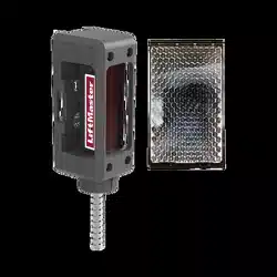
Monitored Protector System models CPS-RPEN4 and CPS-RPEN4GM, are single-sided safety
devices providing monitored entrapment protection for use with LiftMaster
®
Commercial Door and Gate
Operators. The CPS-RPEN4 and CPS-RPEN4GM may be installed in areas exposed to rain or moisture. The
images are for reference and your product may look different.
Model CPS-RPEN4 (LiftMaster
®
Commercial
Door Operators)
Model CPS-RPEN4GM (LiftMaster
®
Gate Operators)
Logic 4 FDCL Commercial Door Operator CSL24V Series RSW12V Series LA500
Medium Duty Logic FDOA Commercial Door Operator CSW24V Series LA400
FDC Commercial Door
Operator
FDOB Commercial Door Operator RSL12V Series LA412
LIFTMASTER
®
MONITORED PROTECTOR SYSTEM
IMPORTANT INFORMATION ABOUT THE PHOTOELECTRIC SENSOR
Be sure power to the operator is disconnected.
When properly connected and aligned, the photoelectric sensor will detect an obstruction in the path of its
beam. If an obstruction breaks the beam while the door/gate is closing, the operator will stop and typically
reverse to the full open position.
The photoelectric sensor must be installed so that it faces the refl ector across the entrapment zone, no more
than 6" (15 cm) above the fl oor for a door and no more than 27.5" (69.6 cm) above grade for a gate. Minimum
installation width of 5 feet and maximum width of 50 feet. The devices can either be installed on the left or right
of the entrapment zone.
The brackets must be securely fastened to a solid surface such as the wall framing. If installing in masonry
construction, add a piece of wood at each location to avoid drilling extra holes in masonry if repositioning is
necessary.
The invisible light beam path must be unobstructed. No part of the gate or door (or door tracks, springs,
hinges, rollers or other hardware) may interrupt the beam while the door/gate is closing.
CARTON INVENTORY
Photoelectric Sensor. . . . . . . . . . . . . . . . . . . . . . . (1)
Mounting Brackets . . . . . . . . . . . . . . . . . . . . . . . . (2)
Refl ector . . . . . . . . . . . . . . . . . . . . . . . . . . . . . . . . (1)
Refl ector Support Bracket. . . . . . . . . . . . . . . . . . . (1)
Installation Instruction . . . . . . . . . . . . . . . . . . . . . (1)
Self-tapping Screws . . . . . . . . . . . . . . . . . . . . . . . (4)
To prevent possible SERIOUS INJURY or DEATH from a closing door or gate:
• Be sure to DISCONNECT POWER to the operator BEFORE installing the photoelectric sensor.
• The door or gate MUST be in the fully opened or closed position BEFORE installing the LiftMaster
®
Monitored Entrapment Protection device.
• Correctly connect and align the photoelectric sensor.
• Install the photoelectric sensor beam NO HIGHER than 6" (15 cm) above the fl oor for door and
27.5" (69.8 cm) above grade for gate operators.
• LiftMaster
®
Monitored Entrapment Protection devices are for use with LiftMaster
®
Commercial Door
and Gate Operators ONLY. Use with ANY other product voids the warranty.
• Entrapment protection devices MUST be installed per the operator owner's manual for each Entrapment
Zone.
LIFTMASTER
®
MONITORED
PROTECTOR SYSTEM
MODELS CPS-RPEN4 AND CPS-RPEN4GM
For more information visit www.devancocanada.com
2
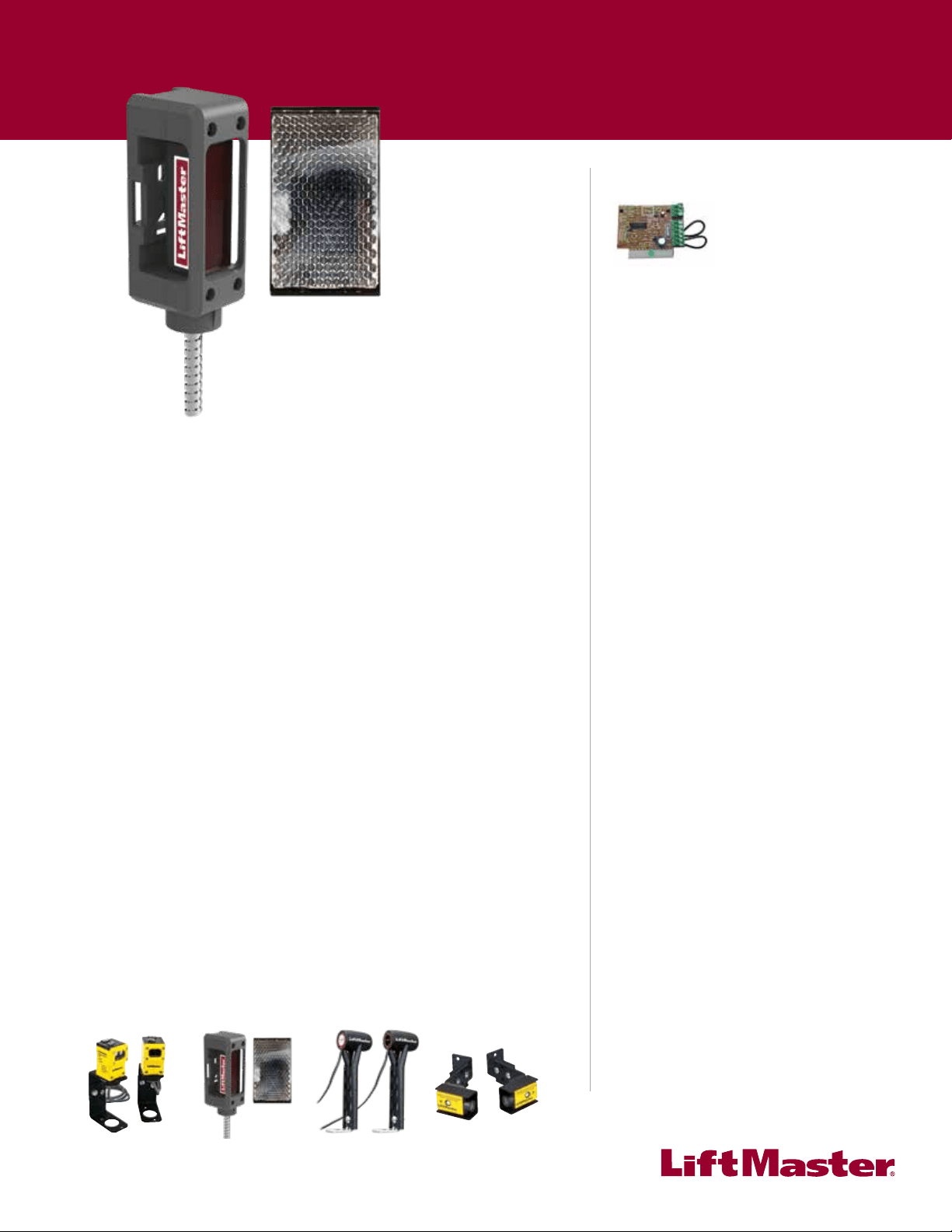
ENTRAPMENT ZONES
Make sure the brackets are aligned so the photoelectric sensor and refl ector will face each other across the
entrapment zone as illustrated. Determine the confi guration for your brackets.
!
Inside
Property
Outside
Property
Outside
Property
Inside
Property
!
!
SWING GATE ENTRAPMENT ZONES
GATE APPLICATION (MODEL CPS-RPEN4GM)
SLIDE GATE ENTRAPMENT ZONES
Photoelectric
Sensor
Photoelectric
Sensor
Photoelectric
Sensor
Photoelectric
Sensor
Refl ector
Refl ector
Refl ector
Refl ector
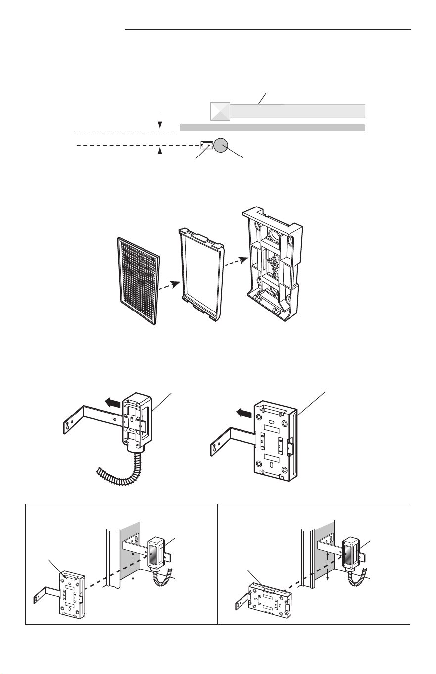
6" (15 cm) max. above the
fl oor and away from the door.
Facing the door from inside the building
(installation procedures are the same for all door types).
Photoelectric
Sensor
Refl ector
Invisible Light Beam
Protection Area
Entrapment Zone
6" (15 cm) max. above the
fl oor and away from the door.
COMMERCIAL DOOR APPLICATION (MODEL CPS-RPEN4)
COMMERCIAL DOOR ENTRAPMENT ZONE
FOR HIGHLY CORROSIVE ENVIRONMENTS
RAY-RT is recommended for installation in locations
near saltwater or chemicals instead of the fl exible conduit
supplied with the sensor. The RAY-RT easily fi ts into
standard ½"-14 NPSM thread connectors.
RAY-RT
3
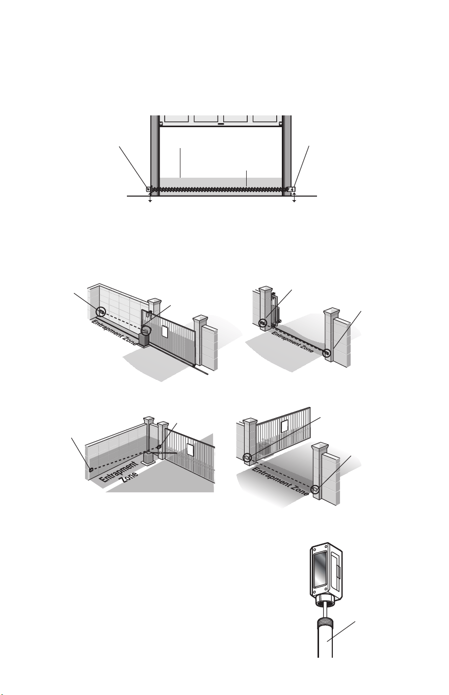
COMMERCIAL DOOR APPLICATION
INSTALLATION
1. Assemble refl ector.
3. Attach mounting bracket to solid surface with hardware (not provided).
NOTE: Track mounting is not recommended.
2. Slide the photoelectric sensor and the refl ector onto the mounting brackets and secure with self-tapping
screws provided. The photoelectric sensor and refl ector must be aligned with the same orientation.
WALL MOUNT
Hardware
(Not provided)
6"
6"
6"
Hardware
(Not provided)
FLOOR MOUNT
Hardware
(Not provided)
DIRECT MOUNT
(WITHOUT MOUNTING BRACKET)
WALL MOUNTFLOOR MOUNT
Photoelectric
Sensor
Photoelectric
Sensor
Refl ector
Refl ector
CORRECT INCORRECT
Photoelectric
Sensor
Reflector
Photoelectric
Sensor
Reflector
4
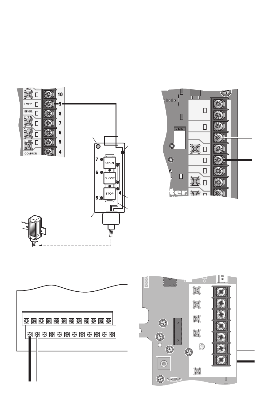
WIRING CONNECTIONS
Be sure power to the operator is disconnected. Do not run control wiring in the same conduit
with AC power.
The wire cable is intended to aid in installation to either a junction box on the wall or can be routed through
the control station mounted next to the door allowing the wires to run in the same conduit as the controls. The
photoelectric sensor also is capable of receiving a 1/2" thread conduit.
Connect the photoelectric sensor as illustrated below for your operator type. The wiring is polarity sensitive so
make certain to wire as indicated below.
TTC
24VAC
24VAC
LMEP:
EDGE:
OPEN
CLOSE
MAS
COMMON
TIMER
DEFEAT
POWER
TIMER
ENABLE
3
3-PHASE
1-PHASE
Blue
Brown
LOGIC 4.0LOGIC 4.0 - INCORPORATING THE CONTROL STATION
Control Board
^^^^
D14
COM INTRLK STOP
LED
OPEN
CLOSE
TTC
LEARN
1
LMEP1 LMEP2
2 345 67
STOP CLOSE OPEN
Blue
Brown
MEDIUM DUTY LOGIC
Control Board
COMMERCIAL DOOR OPERATORS
MODELS FDC, FDCL, FDOA, AND FDOB
J2
1 2 3 4 5 6 7 8 9 10 11 12
13 14 15 16 17 18 19 20 21 22 23 24
Blue
Brown
Control Board
Maintenance
Alert LED
Wire
Nut
Brown
Blue
Control
Station
Control Board
This method requires one additional
wire connection from the operator to
the control station (total of 6 wires
from the operator to the control
station is recommended).
5
CORRECT INCORRECT
Photoelectric
Sensor
Reflector
Photoelectric
Sensor
Reflector
5" (12.7 cm) max. gap
Edge of Gate Panel
Invisible Light Beam
Photoelectric
Sensor
Mounting
Post
Wall or Fence
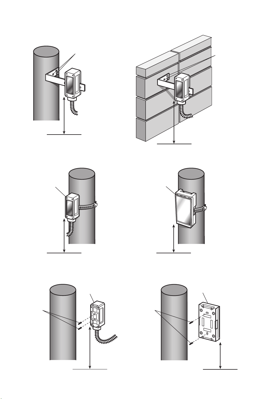
GATE APPLICATION
INSTALLATION
Install the photoelectric sensors and refl ector up to 5" (12.7 cm) maximum from the gate.
1. Assemble refl ector.
2. Slide the photoelectric sensor and the refl ector onto the mounting brackets and secure with self-tapping
screws provided. The photoelectric sensor and refl ector must be aligned with the same orientation.
Photoelectric Sensor Refl ector
6
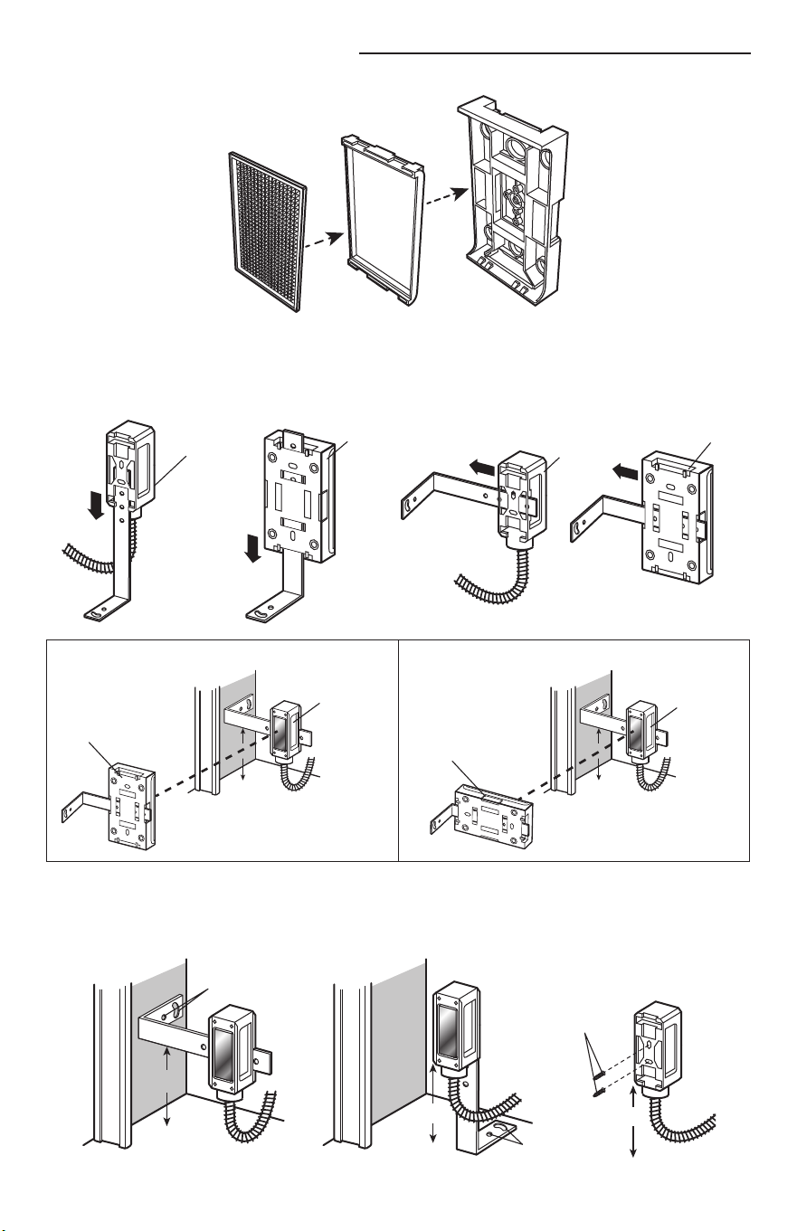
MOUNTING WITH BANDING TECHNIQUE
DIRECT MOUNT (WITHOUT BRACKET PROVIDED)
Photoelectric Sensor
Photoelectric Sensor
Refl ector
Refl ector
POST MOUNT WITH BRACKET (PROVIDED) WALL MOUNT WITH BRACKET (PROVIDED)
Hardware
(Not provided)
Hardware
(Not provided)
3. Attach mounting bracket to solid surface with hardware (not provided).
Hardware
(Not provided)
Hardware
(Not provided)
27.5" maximum
above grade
27.5" maximum
above grade
27.5" maximum
above grade
27.5" maximum
above grade
27.5"
maximum
above grade
27.5"
maximum
above grade
GROUND GROUND
GROUND
GROUND
GROUND
GROUND
7
Z22
R91
R94
R92
R93
OPEN EDGE/
PHOTO
OPEN
PHOTO
CLOSE
PHOTO
R227
R2
Ø
7
Z2
Ø
Z9
Z8
R224
24V
SWITCHED
STOP
G
NOSTIC
C
ODES
EXIT
SHADOW
CLOSE
EYES/
INTERRUPT
- +
+ -
5
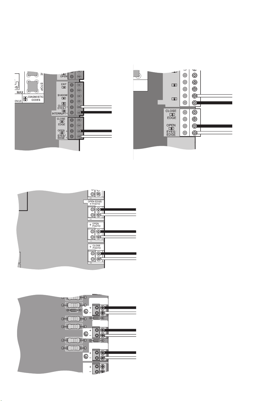
WIRING CONNECTIONS
Be sure power to the operator is disconnected.
The photoelectric sensor is capable of receiving a 1/2" threaded conduit. Connect the photoelectric sensor
as illustrated below for your operator type. The wiring is polarity sensitive, connect the BLUE wire to the '-'
terminal and the BROWN wire to the '+' terminal.
MODELS LA412, RSW12V, AND RSL12V SERIES
MODELS CSL24V SERIES AND CSW24V SERIES
-
-
-
-
-
-
-
-
+
+
+
+
+
+
+
+
Sensor for CLOSE
cycle.
Sensor for OPEN
cycle.
Control Board
Control Board
Sensor for CLOSE cycle.
Sensor for OPEN cycle.
Sensor for OPEN cycle.
MODEL LA500 SERIES
MODEL LA400 SERIES
Control Board
Control Board
-
-
+
+
Sensor for CLOSE
cycle.
Sensor for OPEN
cycle.
Sensor for CLOSE cycle.
Sensor for OPEN cycle.
Sensor for OPEN cycle.
8
TROUBLESHOOTING
REPLACEMENT PARTS LIST
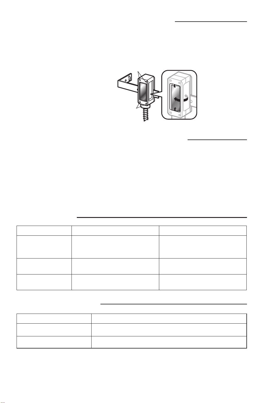
ALIGN THE PHOTOELECTRIC SENSOR AND REFLECTOR
TEST THE LIFTMASTER MONITORED PROTECTOR SYSTEM
The photoelectric sensor and refl ector must be aligned with the same orientation. When properly wired and
aligned the amber LED within the photoelectric sensor will not be illuminated. The alignment LED within the
photoelectric sensor will blink rapidly when the eye is not at the optimal positioning. If the LED is solidly
illuminated this indicates it is powered up properly and is not aligned with the refl ector.
Commercial door installations:
The photoelectric sensor works on the close cycle on a LiftMaster commercial door operator only. With
the door in the full open position place an obstruction in the path of the photoelectric sensor and then try a
CLOSE command. The operator should not move. Now remove the obstruction and give the operator a close
command. The door should close and when the path of the photoelectric sensor is obstructed the door should
reverse.
Gate installations:
The photoelectric sensor can be installed to work on either the open or closing cycles. Refer to the gate
operator installation manual for more information.
Symptom Cause Resolution
No alignment LED seen 1. Not wired properly.
2. Wired properly and aligned with
refl ector.
1. Check wiring. Polarity sensitive.
2. None. Working properly.
Alignment LED on solid Wired properly but NOT aligned with
the refl ector.
Adjust photoelectric sensor to refl ector
until the LED goes out.
Alignment LED blinking Indicates the photoelectric sensor is
not optimally aligned with the refl ector.
Adjust photoelectric sensor to refl ector
until the LED goes out.
P/N: Description
RPEN4-BKT Mounting Bracket
RPEN4-RFLCTR Refl ector with Support Bracket
1-800-528-2806
LiftMaster.com
Screws
Screws
For precise alignment to the refl ector,
loosen the screws and rotate the
photoelectric sensor horizontally or
vertically.
HOW TO ORDER
REPAIR PARTS
DEVANCO CANADA
19192 HAY ROAD, UNIT Q
SUMMERSTOWN, ON K0C 2E0
TOLL FREE: 855-931-3334
www.devancocanada.com
WHEN ORDERING REPAIR PARTS
PLEASE SUPPLY THE
FOLLOWING INFORMATION:
3 PART NUMBER
3 DESCRIPTION
3 MODEL NUMBER
