Loading ...
Loading ...
Loading ...
95 PB
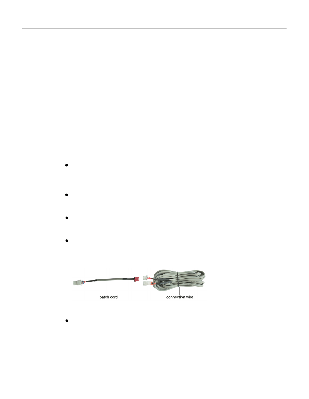
Fig. A: Schematic diagram of patch cord and connection wire
Wired Controller FSWC1 Owner's Manual
(5) Block the four-core wire into the groove at the left side of wiring column; bundle
the front panel of wired controller to its soleplate.
24
Note:
the power cord and connection lines between the indoor and outdoor unit, with a
interference,then the signal and communication lines of the wired controller must
connects the centralized controller
(fig. C)
. The connecting method for the 2-core connection
wire is same as that of 4-core connection wire.
be the shielding twisted pair lines.
minimum interval of 20cm, otherwise the communication of the unit will probably
work abnormally.
Separate the signal and communication lines of the wired controller from
If the air conditioning unit is installed where is vulnerable to electromagnetic
No need
to set the wire of wired controller into the clasp.
The 4-core terminal connects the air conditioner, while the 2-core terminal
(3) Stick the soleplate of wired controller on the wall and then use screw M4×25 to fix
soleplate and installation hole on wall together, attach the sponge 20×20×3 at the
screw hole and then press it with fingers to make sure it’s attached firmly.
(4) Insert the four-core twisted pair line into the slot of the wired controller and then
buckle the front panel and the soleplate of the wired controller together.
If the air conditioner has been installed with the patch cord used for
connecting the wired controller.
For matching with different models, the patch cord and the connection
wire are provided in the packaging box of wired controller. As shown in fig. A.
NOTE:If a longer cable is needed, the cable can be cut and spliced utilizing
22x4AWG-THHN wire. This wire should be SHIELDED if running in areas where
there will be other wiring or electronics near the cable.
WIRED CONTROLLER
Installation Instructions
Fig. 23 Installation diagram for wired controller
Fig. 23 is the simple installation process of wired controller; please pay attention to
the following items:
(1) Before installation, please cut off the power for indoor unit;
(2) Pull out the four-core twisted pair line from the installation holes and then let it go
through the rectangular hole behind the soleplate of the wired controller.
Loading ...
Loading ...
Loading ...