Loading ...
Loading ...
Loading ...
57 PB
INSTALLATION
Installation of the Outdoor Unit
Install the Outdoor Support
1. Select installation location according to the house structure.
2. Fix the support of outdoor unit on the selected location with expansion screws.
Notes
1. Take sufficient protective measures when installing the outdoor unit.
2. Make sure the support can withstand at least four times the unit weight.
3. The outdoor unit should be installed at least 1 1/6inch above the floor in order to install drain joint.(As show in
Fig.18)
Drain hose
Chassis
Outdoor drain joint
Drain vent
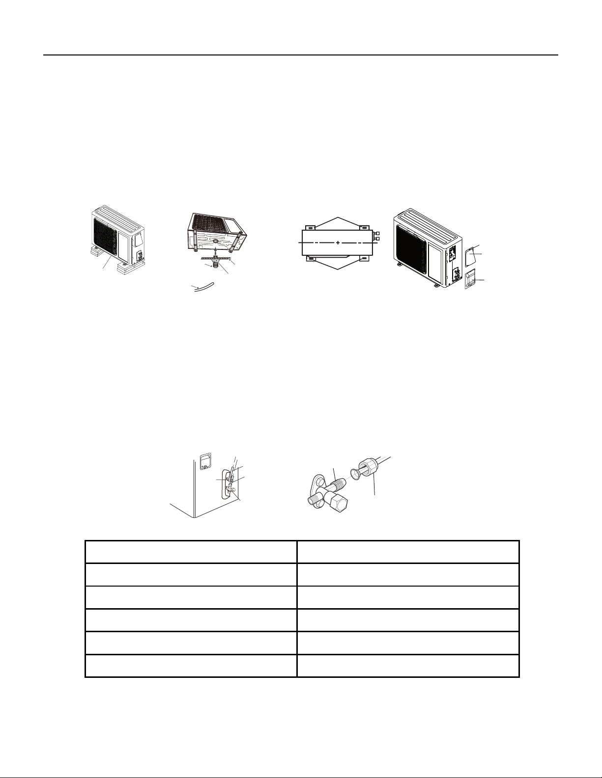
Fig.18 Fig.19
At least 1 1/6 inch
above the oor
Foot holes
Foot holes
Fig.20
Fig.21
Screw
Cable Cross
Plate Sub-assy
Valve Cover
Install Drain Joint ( For Colling and Heating Unit Only)
1. Connect the outdoor drain joint into the hole on the chassis.
2. Connect the drain hose into the drain vent. (As show in Fig.19)
Fix the Outdoor Unit
1. Place the outdoor unit on the support.
2. Fix the foot holes of outdoor unit with bolts.(As show in Fig.20)
Connect Indoor and Outdoor Pipes
1. Remove the screw on the right cable cross plate sub‑assy and valve cover of outdoor unit and then remove the
cable cross plate sub‑assy and valve cover.(As show in Fig.21)
2. Remove the screw cap of valve and aim the pipe joint at the bellmouth of pipe.(As show in Fig.22)
3. Pretightening the union nut with hand.
4. Tighten the union nut with torque wrench .
Refer to the figure 22a for wrench moment of force
gas pipe
Liquid pipe
Liquid
valve
gas valve
Union nut
Pipe joint
Fig.22
Hex nut diameter(inch) Tightening torque(ft∙Ibf)
Φ1/4 11~14.7
Φ3/8 22.8~29.5
Φ1/2 33.2~40.6
Φ5/8 44.3~47.9
Φ3/4 51.6~55.3
Fig. 22a
Loading ...
Loading ...
Loading ...