Loading ...
Loading ...
Loading ...
53 PB
INSTALLATION
Installation of Indoor Unit
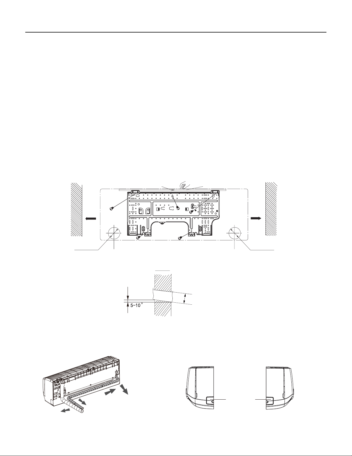
Install Wall Mounting Frame
1. Hang the wall‑mounting frame on the wall; adjust it in horizontal position with the level meter and then point out the screw fixing holes
on the wall.
2. Drill the screw fixing holes on the wall with impact drill (the specification of drill head should be the same as the plastic expansion
particle) and then fill the plastic expansion particles in the holes.
3. Fix the wall‑mounting frame on the wall with tapping screws (ST4.2X25TA) and then check if the frame is firmly installed by pulling the
frame. If the plastic expansion particle is loose, please drill another fixing hole nearby.
4. Choose the position of piping hole according to the direction of outlet pipe. The position of piping hole should be a little
lower than the wall‑mounted frame.(As show in Fig.1)
5. Open a piping hole with the diameter of 2 3/4inch on the selected outlet pipe position.In order to drain smoothly, slant the
piping hole on the wall slightly downward to the outdoor side with the gradient of 5‑10°.(As show in Fig.2)
Note:
1. Pay attention to dust prevention and take relevant safety measures when opening the hole.
2. The plastic expansion particles are not provided and should be bought locally.
Fig.1
6inch
6inch
Wall
Wall
Mark on the middle of it
Gradienter
Left
Right
(Rear piping hole) (Rear piping hole)
Space
to the
wall
above
Space
to the
wall
above
Φ2 1/16inch
Φ2 3/16inch
Φ2 3/4inch
Φ2 1/16inch
Φ2 3/16inch
Φ2 3/4inch
Φ2 1/16inch
Φ2 3/16inch
Φ2 3/4inch
Indoor
Outdoor
Fig.2
Outlet Pipe
1. The pipe can be led out in the direction of right, rear right, left or rear left.(As show in Fig.3)
2. When selecting leading out the pipe from left or right, please cut off the corresponding hole on the bottom case.(As show in Fig.4)
Left
Rear left
Right
Rear right
Fig. 3
Cut off
the hole
Left Right
g. 4
Loading ...
Loading ...
Loading ...