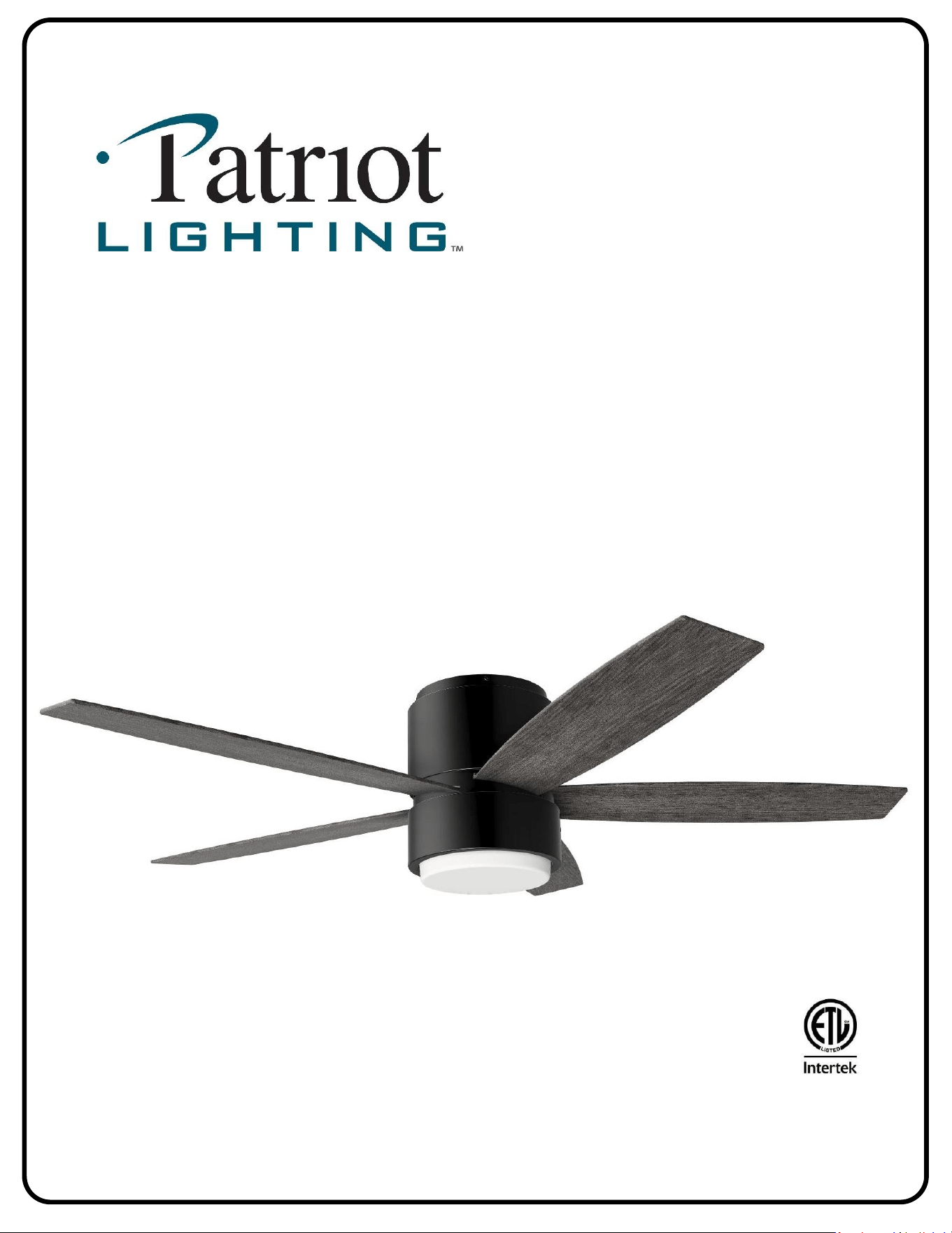
52” Apex
Indoor Ceiling Fan
Owner’s Manual
Models #25208/09
SKU #s 355-1606, 355-1608
SAFETY INSTRUCTIONS
1
WARNING:
• To avoid risk of electrical shock, be sure to shut off power at the main fuse or circuit breaker
panel box before installing or servicing this fixture. Turning off the electrical power by using the
light switch only is not sufficient to prevent electrical shock hazard.
• To reduce the risk of fire, electric shock, or personal injury, mount fan to an outlet box marked
“acceptable for fan support up to 35 lbs. (16 kg)” and use mounting screws provided with the
outlet box. The total weight of this fan is approximately 18 lbs. (8.2 kg).
• All wiring must be in accordance with the National Electrical Code ANSI/NFPA 70 and any
applicable local codes. Electrical installation should be performed by a qualified licensed
electrician.
• To reduce the risk of fire or electric shock, do not use this fan with any solid-state speed control
device.
• Do not bend the blade iron brackets when installing the brackets, balancing the blades, or
cleaning the fan. Do not insert foreign objects in between rotating fan blades.
CAUTION:
• To reduce the risk of injury, install the fan so that the blades are at least 7 feet (2.1 meters)
above the floor and at least 30 inches (0.76 meters) from the tip of the blades to the wall.
• Check and retighten all screws, nuts, and bolts to ensure they are secured prior to operating the
fan.
• Be sure the outlet box is properly grounded and that a ground wire (green or bare) is present.
• When changing (reversing) the blade direction, turn off the fan and wait for the fan blades to
stop completely.
• To reduce the risk of serious bodily injury, do not use power tools to assemble any part of the
fan, including the blades.
• To reduce the risk of personal injury, use only parts provided with this fan. The use of parts
other than those provided with this fan will void the warranty.
• Do not use water or detergents when cleaning the fan or fan blades. A dry dust cloth or lightly
dampened cloth is recommended to prevent scratching and will be suitable for most cleaning.
• In case this fan needs to be returned to the factory for repairs, it must be shipped in its original
carton and foam packaging to ensure proper protection against shipping damage that may
exceed the initial cause for return.
• Please read and understand these safety instructions and the installation guide before
attempting to assemble, install, or operate the fan.
2
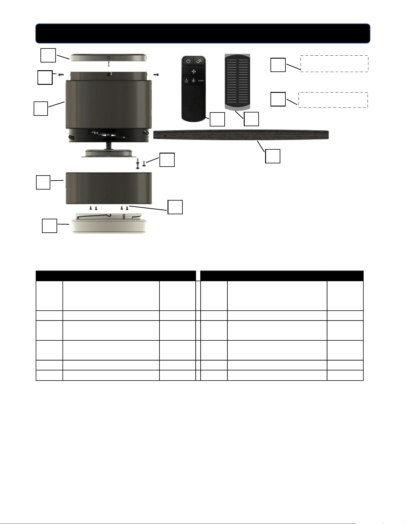
PACKAGE CONTENTS
PART DESCRIPTION QUANTITY PART DESCRIPTION QUANTITY
A Ceiling mounting bracket 1 G
Light kit housing screws (pre-
installed on bottom of motor
housing)
4
B Upper motor housing 1 H Light kit glass 1
C Upper motor housing screws 4 I
Handheld remote control and
(2) AAA batteries
1
D
Blades 5 J
Remote receiver with 9-pin
connector
1
E Blade screws and washers 15 K Owner's manual 1
F Light kit housing 1 L
Hardware bag and balancing kit 1
HARDWARE KIT
OWNER’S MANUAL
A
G
B
D
C
H
I
L
K
E
F
J
3
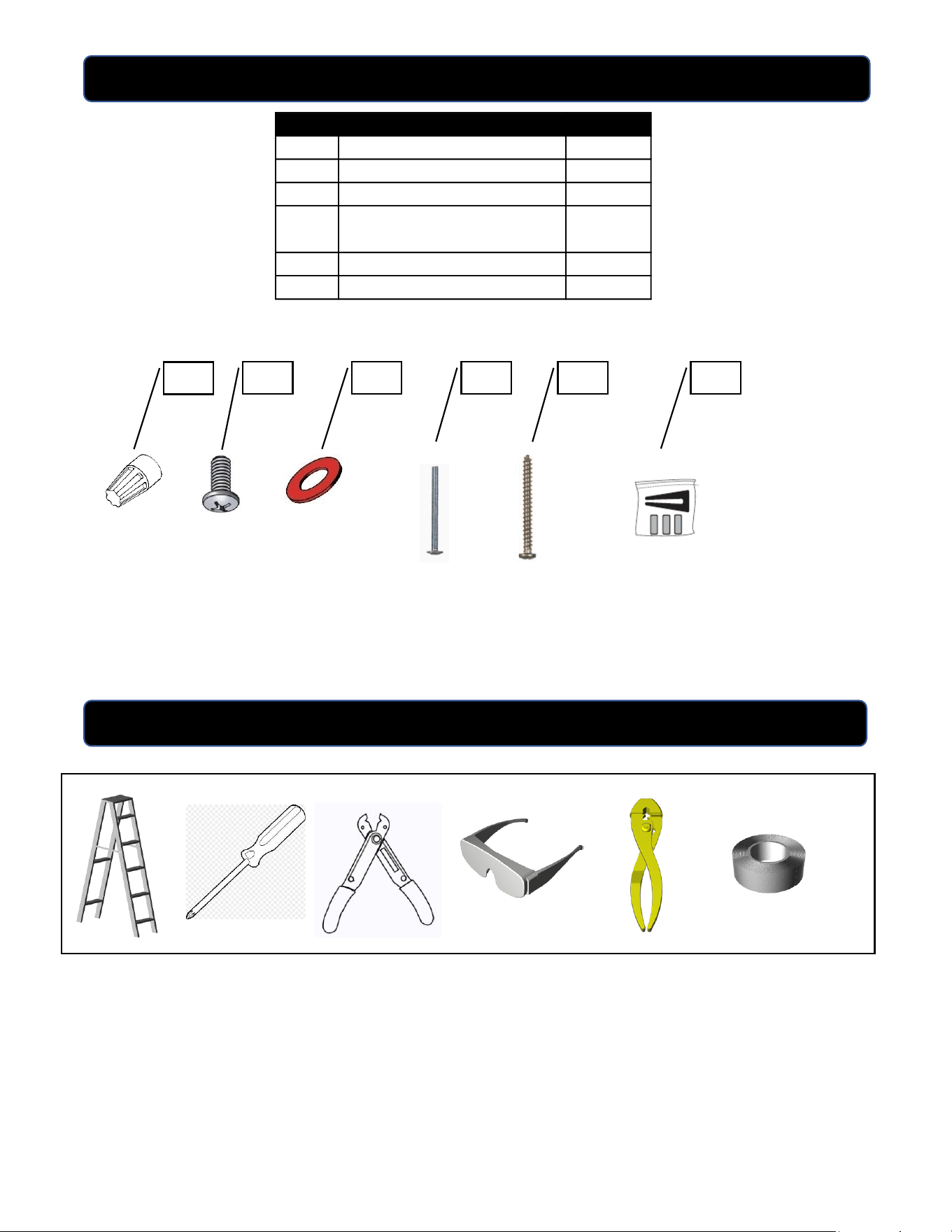
HARDWARE KIT CONTENTS
NOTE: For your convenience some extra hardware may be included. The quantity listed
above is the number required for installation.
Tools required for assembly: Step Ladder, Phillips Screwdriver, Wire Strippers, Safety
Glasses, Pliers, and Electrical Tape.
Helpful Tools: AC Tester Light/Multimeter, Tape Measure, and Wiring Handbook
PART DESCRIPTION QUANTITY
AA
Wire connectors 5
BB Blade screws 15
CC Fiber blade washers 15
DD
Machine screws and lock
washers
2 each
EE Wood screws and washers 2 each
FF Balance kit 1
TOOLS REQUIRED (not included)
AA
BB
FF
CC
DD
EE
4
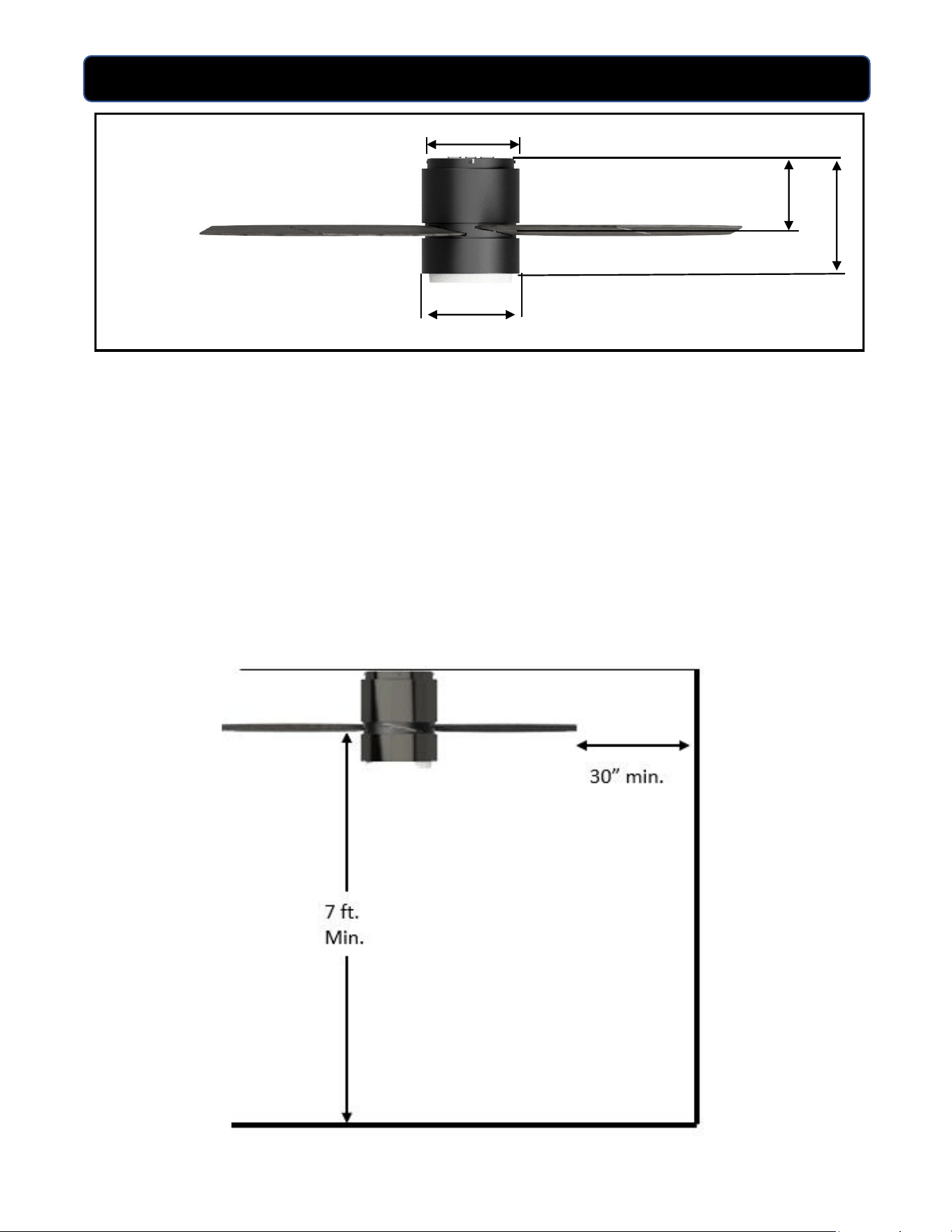
DIMENSION REFERENCE
A: 11.5 in.
B: 7.4 in.
C: 9.1 in.
D: 8.1 in.
NOTE: Make sure blades are at least 30 inches from any wall or obstruction and at least
7 feet above the floor.
A
B
N
C
D
5
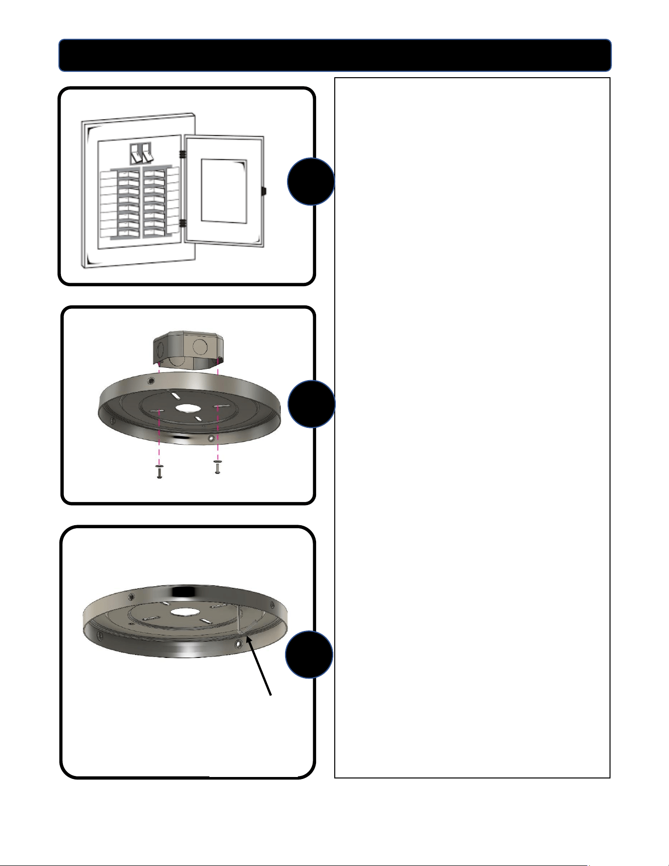
ASSEMBLY INSTRUCTIONS
1. Turn OFF the electrical power at the
main fuse or circuit breakers.
NOTE: Before continuing installation,
confirm that the power is still turned
off at the main circuit breaker or by
removing the correct fuse. Turning
the power off using a wall switch is
not sufficient to prevent electrical
shock.
2. Secure the mounting bracket to the
outlet box (not included) using the
screws and washers provided with the
outlet box. Feed the wires from the
ceiling box through the center hole of
the mounting bracket.
WARNING: To reduce the risk of fire
electrical shock, or personal injury,
mount to the outlet box marked
“acceptable for fan support” using the
mounting screws and washers
provided with the outlet box.
3. Note the hanging hook on the under-
side of the mounting bracket. The
upper motor housing will be
temporarily hung from this hanging
hook in the next step.
1
2
3
6
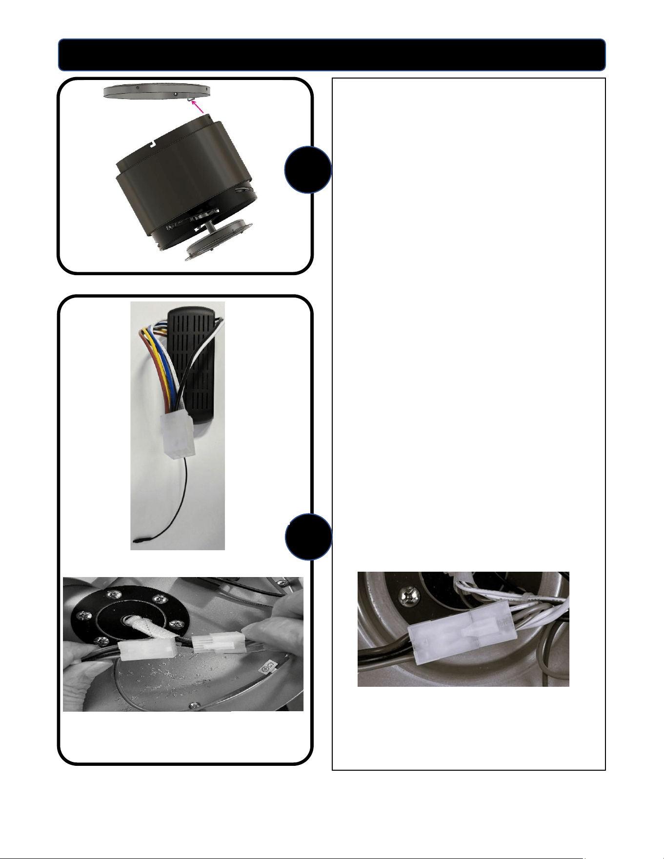
ASSEMBLY INSTRUCTIONS
4. Utilizing one of the holes in the top
ring of the upper motor housing, hang
the housing from the mounting hook
as shown. This will allow for hands-
free wiring of the fan.
5. Place the remote receiver with the 9-
pin connector (image A) in the top of
the motor housing.
The 9-pin wiring harness secures the
connection between the fan and
remote receiver. Line up the two 9-
pin plugs and connect until snug. The
side with the clip needs to line up
with the side that has the clip catch.
See image B.
The completed 9-pin connection
should look like the image below.
4
5
Image A
Image B
7
ASSEMBLY INSTRUCTIONS
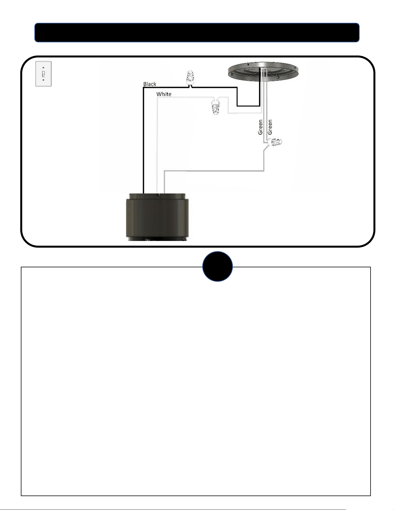
Single switch wiring
6. WIRING THE FAN: SINGLE WALL SWITCH
Use the supplied wire connectors to connect the wires from the remote receiver to the power supply wires
coming out of the ceiling according to the wiring diagram and following instructions:
Connecting the remote receiver to the power supply:
• Connect the white wire from the receiver to the white wire coming from the ceiling. Secure with wire
nut.
• Connect the black wire from the receiver to the black wire coming from the ceiling. Secure with wire
nut.
• Connect all green (ground) wires together: Connect the green wire from the fan to the green wire from
the mounting bracket and the green wire from the ceiling. Secure with wire nut.
Note: The black rubber wire coming out of the receiver is the antenna. Tuck that antenna wire alongside the
inside of the top of the motor housing by the receiver so that it is out of the way when securing the motor
housing to the ceiling bracket in the next step. The antenna wire is to remain on the inside of the motor
housing. The antenna wire should not be tucked up into the ceiling outlet box.
IMPORTANT: After the connections have been made, make sure all connections are secure, and the wires do not come loose
from the wire nuts. All wiring must meet local and national building codes. If you are unfamiliar or not comfortable with wiring,
please consult a qualified electrician.
6
8
ASSEMBLY INSTRUCTIONS
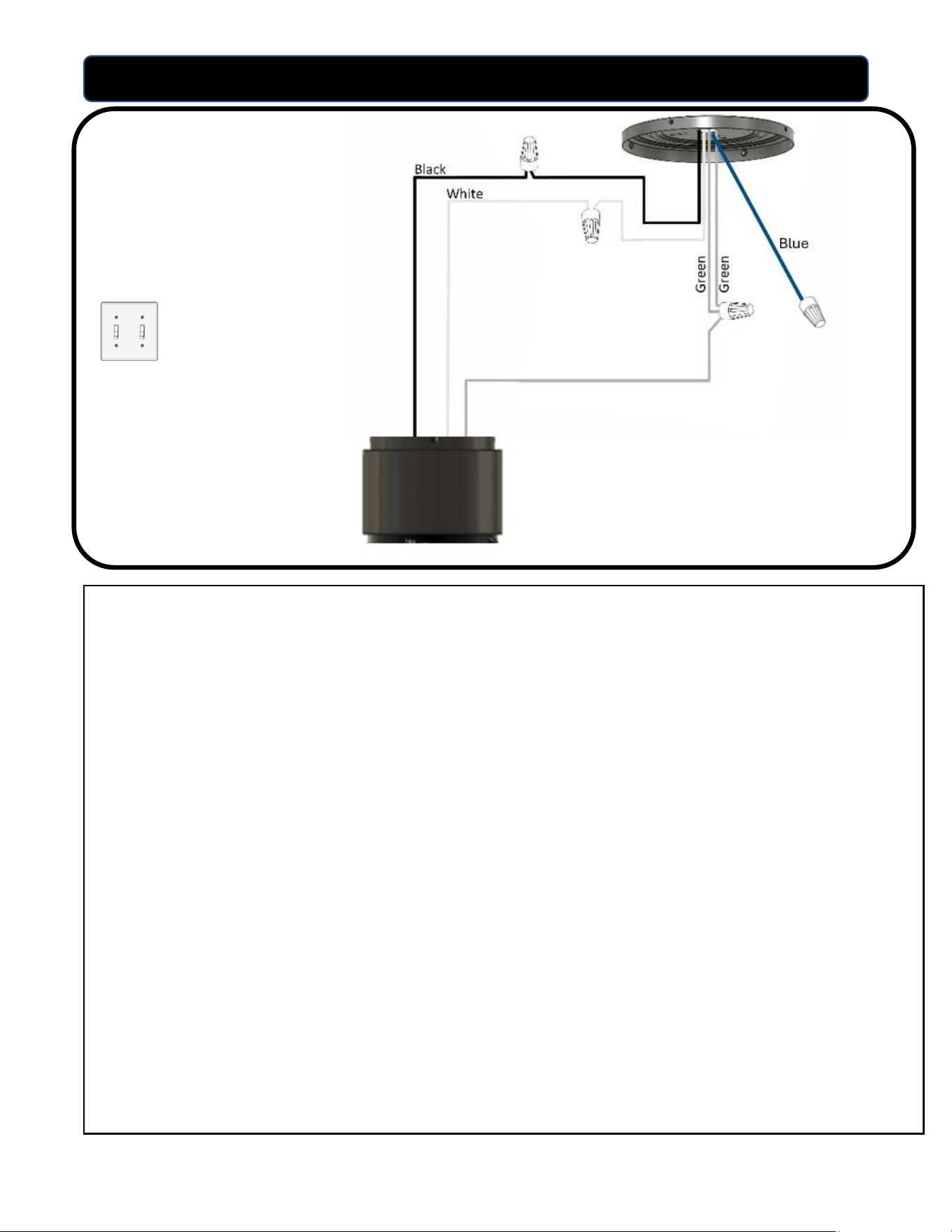
6. WIRING THE FAN: DUAL SWITCH WIRING
Use the supplied wire connectors to connect the wires from the remote receiver to the power supply wires
coming out of the ceiling according to the wiring diagram and following instructions:
Connecting the remote receiver to the power supply:
• Connect the white wire from the receiver to the white wire coming from the ceiling. Secure with wire
nut. Connect the black wire from the receiver to the black wire coming from the ceiling. Secure with
wire nut.
• Cap off the blue (or red) wire coming from the ceiling with a wire nut. This wire previously controlled
the second wall switch, but with the remote control now controlling both the light and the fan this
switch is no longer needed.
• Connect all green (ground) wires together: Connect the green wire from the fan to the green wire from
the mounting bracket and the green wire from the ceiling. Secure with wire nut.
Note: The black rubber wire coming out of the receiver is the antenna. Tuck that antenna wire alongside
the inside of the top of the motor housing by the receiver so that it is out of the way when securing the
motor housing to the ceiling bracket in the next step. The antenna wire is to remain on the inside of the
motor housing. The antenna wire should not be tucked up into the ceiling outlet box.
IMPORTANT: After the connections have been made, make sure all connections are secure, and the wires do not come loose
from the wire nuts. All wiring must meet local and national building codes. If you are unfamiliar or not comfortable with wiring,
please consult a qualified electrician.
Dual switch wiring
9
ASSEMBLY INSTRUCTIONS
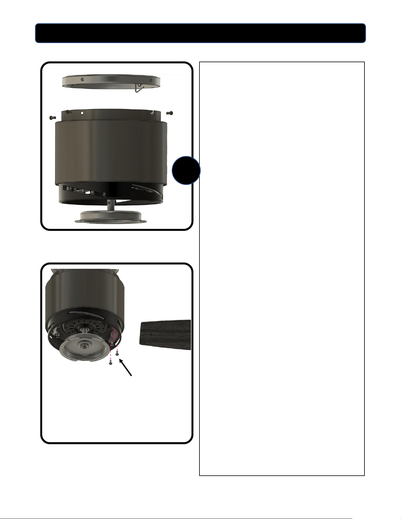
7. SECURING THE MOTOR HOUSING
Remove two mounting screws opposite
from each other from the top of the motor
housing. Slightly loosen the two remaining
screws.
Remove the motor housing body from the
bracket hook and swing the fan up into
place onto the ceiling bracket.
Note: When swinging the fan up onto the
bracket, be sure that the mounting hook
does not interfere with the remote receiver
or the antenna wire.
Align the two keyhole screw openings with
the two screws that have been loosened
halfway. Position the housing onto the two
screws, slide into place in the keyhole slots,
and tighten the screws. Using the remaining
two screws from the mounting bracket, line
up the other two holes in the side of the
motor housing, insert screws, and tighten
down. Confirm that upper housing is secure.
8. INSTALLING THE BLADES
Insert the blade into the blade slot around
the motor housing and line up the three (3)
holes at the end of the blade with the 3
holes in the motor housing. Secure the
blade to the fan using (3) blade screws and
(3) fiber blade washers.
Repeat for the remaining blades.
Note: To prevent the risk of overtightening,
do not use power tools to assemble the
blades.
7
Blade Screws
and Washers
10
ASSEMBLY INSTRUCTIONS
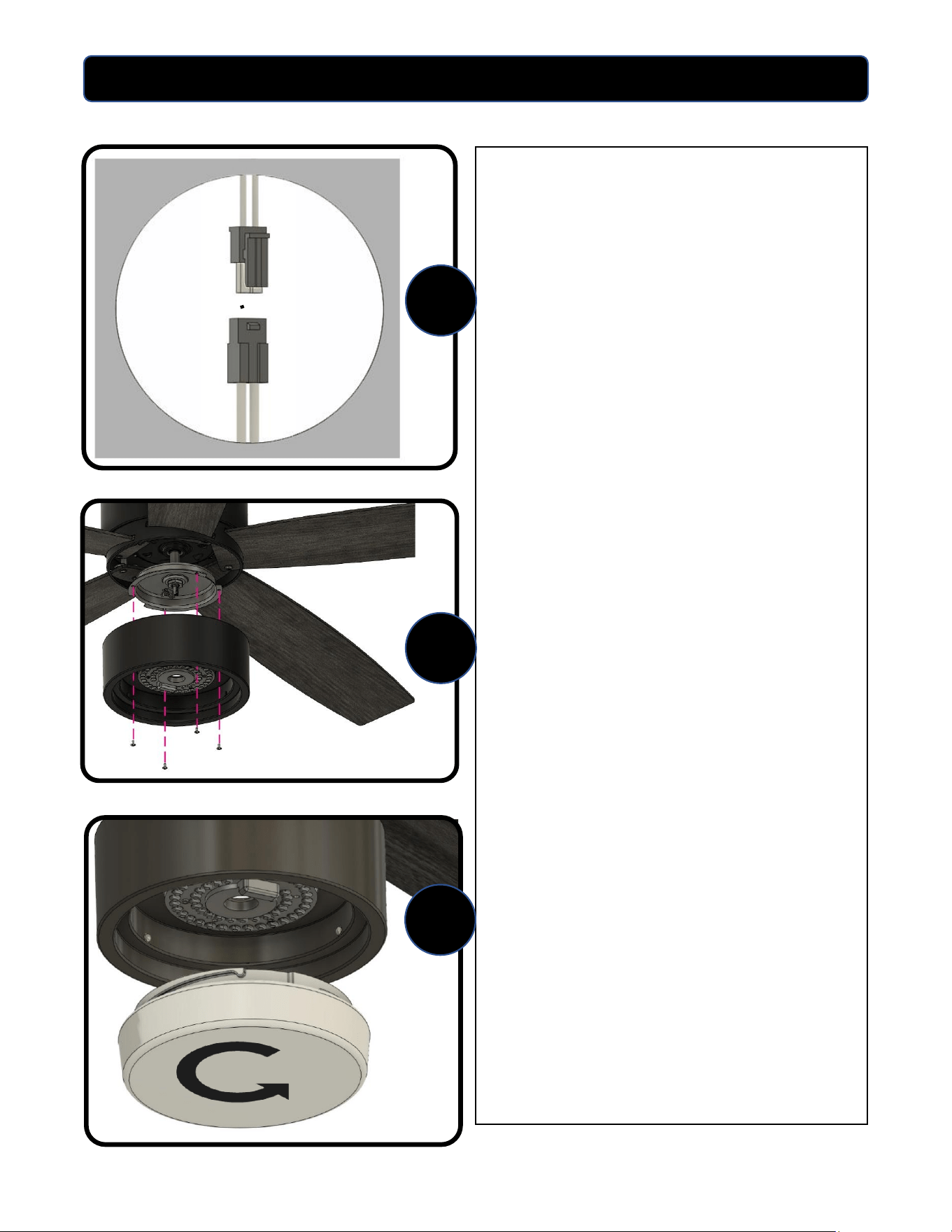
9. CONNECTING THE LIGHT KIT
Position the light kit housing under the
fan. Connect the wiring from the LED
lighting board to the fan wiring by
connecting the two ends of the push-pin
wiring harness. Note: The clip on the
outside of one connector should snap
together with the catch on the other
connector. Push the connectors and
excess wire back up into the center hole
so that it will not block any of the light
output.
10. Remove the (4) pre-installed
screws on the ring on the bottom of fan
and line up the holes with the (4) holes
on the light kit plate. Firmly secure the
light kit plate to the fan with the (4)
screws.
11. INSTALLING THE LIGHT KIT GLASS
Position the glass bowl to line up with
the bottom of the light kit. While holding
the glass up to the bottom of the light
kit, turn the glass clockwise until the
notch in the glass slips into the light kit
channel. Continue to turn clockwise until
snug. DO NOT OVERTIGHTEN.
Assembly complete..
10
9
11
11
ASSEMBLY INSTRUCTIONS
12. Restore the power to the main fuse
or circuit breaker.
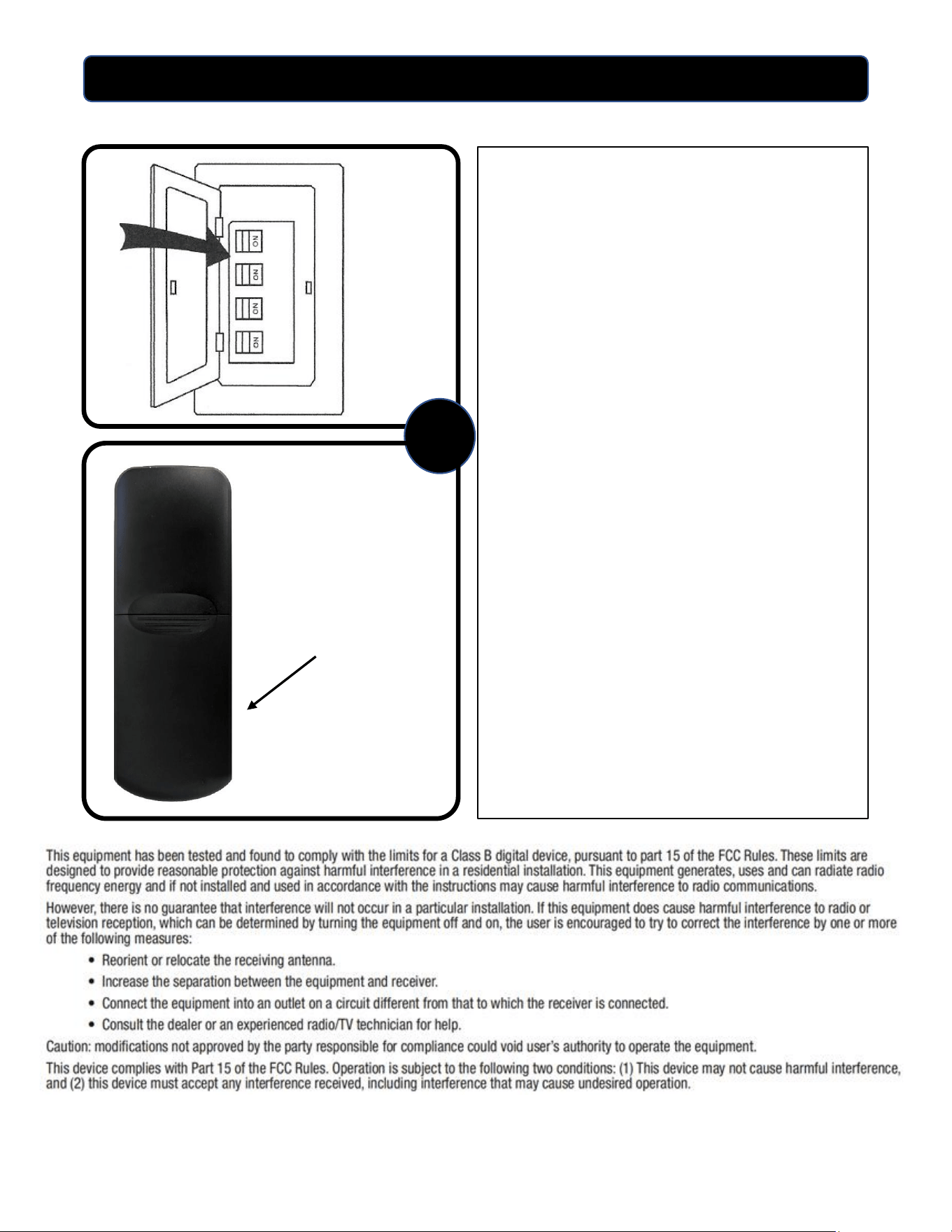
Install the two AAA batteries (included)
into the battery compartment on the
back of the handheld remote control.
12
Battery compartment
12
OPERATING INSTRUCTIONS
Note: Pressing the color temperature button for
longer that 2 – 3 seconds might result in the light
kit to automatically cycle through the five color
temperatures.
To restore your light kit to normal operation
press the color temperature button one time for
1 or 2 seconds.
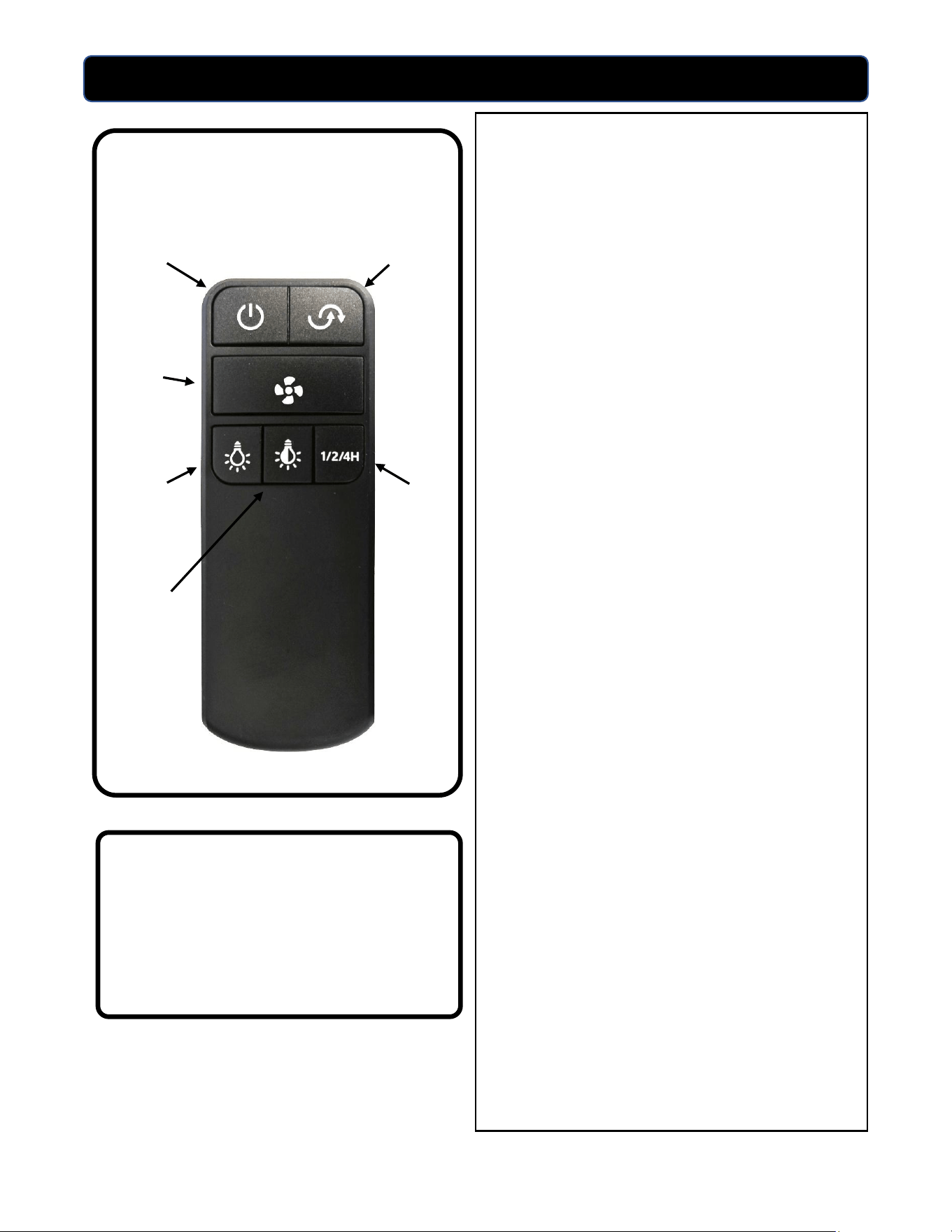
USING THE REMOTE CONTROL
• Power: Turns the fan ON or OFF. When
turning the power OFF, the remote
maintains memory and the next time the
fan is turned ON it will return to the
same fan speed and light status as when
it was turned off. If both the fan and light
are on when the power is turned off, the
light will stay on for 60 seconds for safe
exit out of the room.
• Reverse: Reverses the direction of the
fan blades. With the fan running, press
this button to reverse direction. Fan will
fully stop for up to 5 seconds and then
reverse direction.
• Fan speed: Controls the 3 speeds of the
fan. Sequence is high, medium, low, OFF.
Indicator lights will show three lights for
high, two for medium, and one for low.
• Light dimming: Press once for light ON
and OFF. To adjust light brightness level
push and hold the button. Light will
adjust all the way down and all the way
back up again until button is released.
• Color temperature: With the light ON
adjusts color temperature of the LED
light with a short press of button. Cycle is
soft white (2700K), warm white (3000K),
bright white (3500K), neutral white
(4000K), and cool white (5000K).
• Timer: With the fan ON, offers 1-, 2-, or
4-hour delay for fan and light. Short
press once for 1 hour (LEDs flash 1X),
press again for 2 hours (LEDs flash 2X),
press again for 4 hours (LEDs flash 4X).
Pressing Power button OFF will cancel
timer setting.
Remote Control
Power
Reverse
Fan
Speed
Light
Dimming
Color
Temperature
Timer
13
OPERATING INSTRUCTIONS
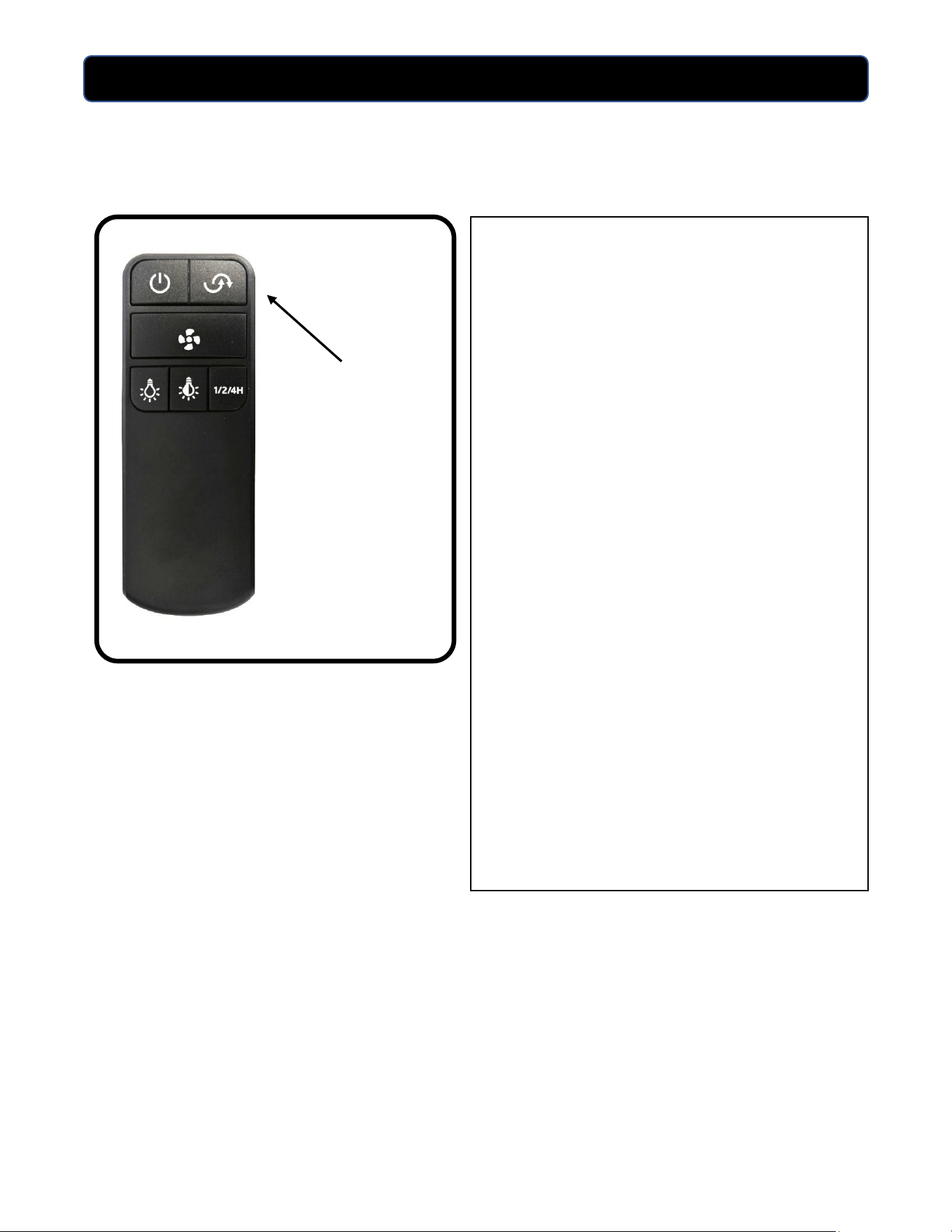
REVERSE BUTTON
Use the fan reverse button, conveniently
located on the handheld remote, to
optimize your fan for seasonal
performance. Using a ceiling fan will
allow you to raise your thermostat setting
in summer and lower your thermostat
setting in winter while saving on heating
and cooling costs.
In warmer weather, set the reverse
function to put the fan blades into a
counterclockwise direction which will
result in downward airflow creating a
wind chill effect.
In cooler weather, set the reverse
function to put the fan blades into a
clockwise direction which will result in
upward airflow that can help move
stagnant, hot air off the ceiling area and
back down into the room.
Reverse
button

14
TROUBLESHOOTING
FAN DOES NOT START:
• Check the circuit breaker and confirm the power is ON.
• Make sure the wall switch is ON.
• Confirm the batteries are installed correctly in the handheld remote; install fresh batteries.
• Make sure you are in the normal range for the remote control of 10’ – 20’ (3m – 6m).
• Check that the motor reversing switch is correctly engaged. With the fan running, push the
reverse switch button once and confirm that the fan stops for up to 5 seconds and then
reverses direction. If the fan has reversed direction then the switch is properly engaged.
• Confirm that the blades spin freely and that there are no obstructions between the blades or
into the motor housing.
• Turn off power at the circuit breaker and at the wall switch, unsecure the fan from the ceiling
mounting plate, put the fan onto the hook used during installation, and check that all wiring
connections from the household supply wires to the remote receiver and to the fan wires are
secure. Confirm the single black antenna wire is tucked inside the upper housing and not
pinched in the mounting plate.
FAN IS NOISY:
• Make sure all screws are snug and secure including blade screws into the motor housing,
screws into the light kit, and screws on the canopy.
• Make sure all blades are properly installed.
• Some ceiling fan motors are sensitive to solid state variable speed wall controls. If the fan is
controlled by these types of controls remove the control and replace it with a standard wall
switch to enable the remote control to operate the fan and light.
FAN WOBBLES:
• Make sure the fan mounting bracket is securely tightened to the ceiling outlet box and the
ceiling box is securely fastened to the ceiling joist or other adequate support structure.
• Make sure all blades are installed correctly, and all screws are secure. Also confirm that the two
set screws in the downrod are tight in the yoke.
• Balance the fan blades using the blade balancing kit included with the fan.
WARNING: Before beginning any troubleshooting or maintenance work always shut off the
power supply to avoid electrical shock hazard.

LIMITED LIFETIME WARRANTY
Model Name: 52” Apex Ceiling Fan
Models: 355-1606 and 355-1608
15
The limited lifetime warranty covers this ceiling fan, for residential use by the original purchaser, against defects
in material or workmanship as follows:
If your Patriot Lighting Ceiling Fan motor fails at any time during the lifetime of the original purchaser due to
defects in material or workmanship, we will provide a replacement part free of charge.
If your fan motor fails at any time within one year after the original date of sale to the original purchaser due to
defects in material or workmanship, we will provide labor to repair the defect, with the exception of take
down/reinstallation, free of charge. The original purchaser will be responsible for all labor costs after this one-
year period.
If no replacement parts are provided for any part of your fan motor that fails at any time during your lifetime
due to defects in material or workmanship, we will refund the original purchase price of your fan.
If your fan blades, pull chain switch, reverse switch, or any accessory, except glass globes and light bulbs, fails at
any time within one year after the original date of purchase due to a defect in material and workmanship, we
will repair or, if we choose, replace the defective blades, switch, or accessory free of charge, with the exception
of take down/reinstallation services.
If the original purchaser ceases to own the fan, this warranty, and any implied warranty, including but not
limited to any implied warranty of merchantability or fitness for a particular purpose, become void. This
warranty and any implied warranty, including but not limited to any implied warranty of merchantability or
fitness for a particular purpose, do not cover glass globes, light bulbs, or finish on any metal portions of the fan.
This warranty is in lieu of express warranties. The duration of any implied warranty of merchantability or fitness
for a particular purpose, with respect to any Patriot Lighting Ceiling Fan motor, blades, switch, or accessories, is
expressly limited to the period of the express warranty set forth above for such motor, blades, switch, or
accessories.
This warranty excludes defects, malfunctions, or failures of any Patriot Lighting Fan that are caused by repairs by
persons not authorized by us, use of parts or accessories not authorized by us, mishandling, improper
installation, modifications, or damage to the fan while in your possession, or unreasonable use, including failure
to provide necessary maintenance.
To obtain service, contact the service department. You will be responsible for all insurance and freight or other
transportation charges to our factory or service center. A copy of the sales receipt is required in order to obtain
service. We will return your fan freight prepaid. Your fan should be properly packed to avoid damage in transit,
for we will not be responsible for any such damage.
In no event shall Patriot Lighting Fan be liable for consequential or incidental damages.
Some states do not allow the exclusion or limitation of consequential or incidental damages, in which case the
above limitation or exclusion may not apply.
This warranty gives you specific legal rights and you may also have other rights which vary from state to state.
To obtain Service, please contact the Service Department: 1-770-486-2000, 8 a.m. – 5 p.m. Central Time.
