SKU Number: 355-3311
Model Number: CFO-2410
20” Indoor/Outdoor Ceiling Fan
Questions, problems, missing parts?
Please email us at [email protected],
or call us at 1-888-722-5089.
B
1
G
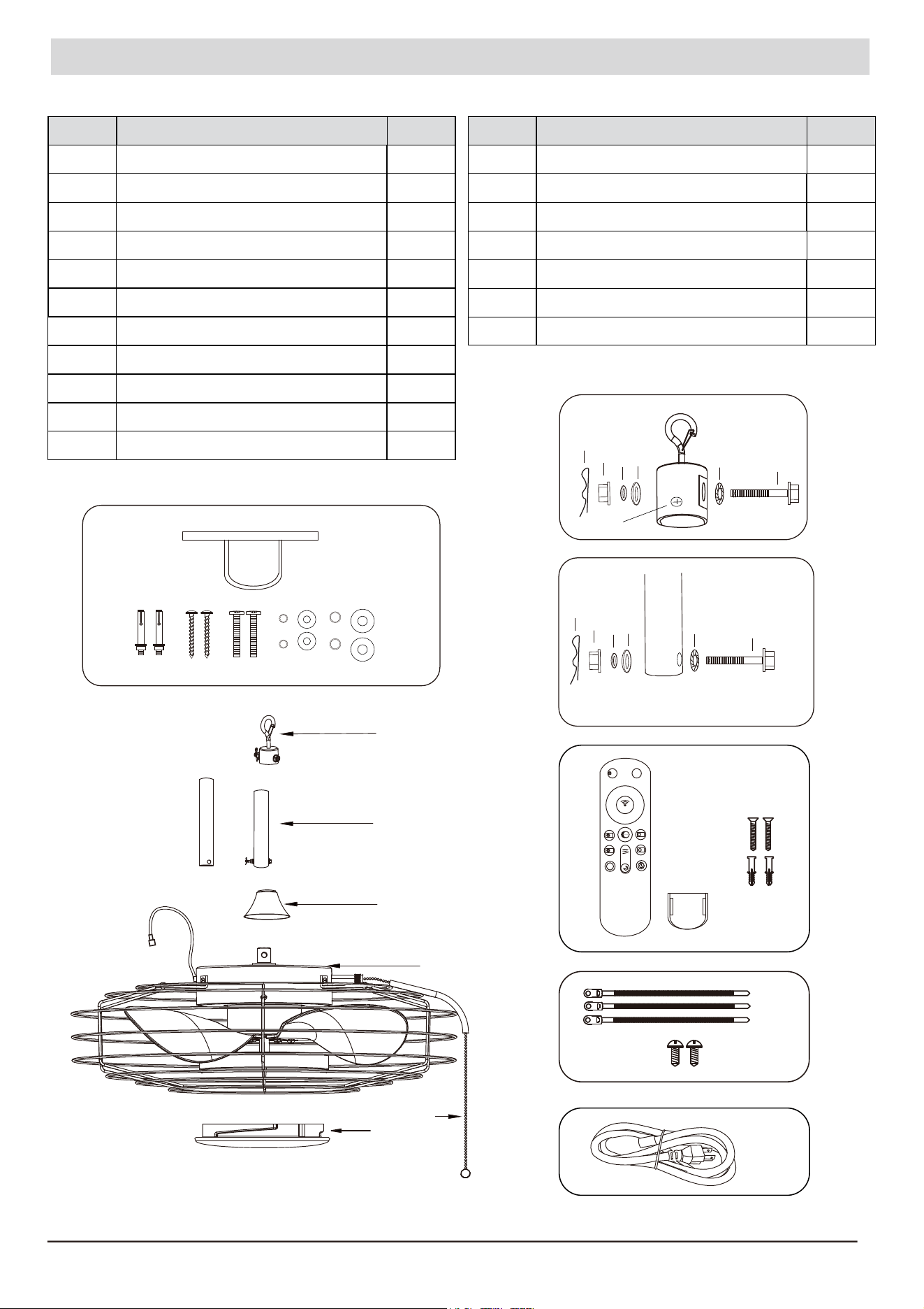
Package Content
S
s
☆
F/R
-
K
-
K
+
+
SETUP
3
6
4
5
2
1
ALL OFF
ON
OFF
K
C
D
J
E
B
K
F
H
I
A
C
cd
e
f
Part Description Quantity
A Hanger Bracket Kit
Hanger Buckle Kit
Downrod ( 6in & 10in )
Coupling Cover
Fan Body
Lamp Shade
Transmitter & Hold Set
Cable Tie
Wall Screw
Power Cord
Pull Chain (Preassembled)
B
C
D
E
F
G
H
I
J
K
1
2
1
1
1
1
1
1
2
3
1
Part Description Quantity
a Bolt 2
2
2
2
2
2
b
c
d
e
f
Tooth Washer
Flat Washer
Spring Washer
Nut
Lock Pin
a
b
cd
e
f
a
b
2
g
Coupling screw
g
2
Planning Installation
Tools required for assembly (not included): Slotted screwdriver, Phillips screwdriver, safety glasses, Ladder.
Pre-installation
- This fan is applicable for gazebos or pagodas where a reliable mounting bracket is provided.
- To reduce risk of fire, electric shock, or injury to persons, unplug or disconnect the appliance from the power supply
before the fan installation, cleaning, or servicing.
- Ensure the hanging structure can support a minimum weight of 65 lbs. lf you are not sure the hanging structure can
support the weight, do not attempt to install this fan as it may fall and cause damage to the fan or personal injury.
- Power cord will not support the weight of a fixture; pulling power cord will result in the fixture falling, with the possibility
of personal injury and the danger of electrical shock or fire.
- To reduce the risk of personal injury, do not insert foreign objects inside the cage of the fan.
- Use only on GFCl-protected receptacles.
- Do not operate any fan with a damaged cord or plug.
- Do not cover cord with throw rugs, runners, or similar coverings.
- Do not route cord under furniture or appliances.
WARNING
Product Specification: 120V 60Hz Weight of the fan: approximate 7.5 lbs
Remove all parts from the package, and verify that everything listed in the Package Contents section are present.
Inspect the product carefully to make sure no breakage or damage occurred during shipping.
1
Assembly Instructions
IMPORTANT: Risk of electrical shock, turn off circuit breaker and wall switch before assembly.
To avoid damage to the wire and plug, do not over-pull.
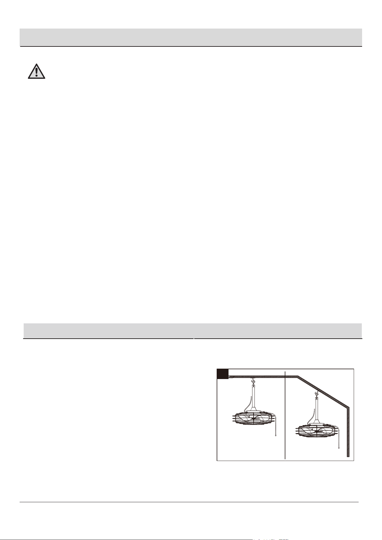
1. Choose the desired mounting method:
A. Standard Mounting:
Note: If a ceiling higher than 8 feet, you can purchase an
extension downrod.
B. Angle Mounting: Angle mounting is used for vaulted
or angled ceilings.
Note: The preferred mounting methods are to gazebos,
pagodas, or drywall which provided the surface
supports a minimum weight of 65 lbs.
A. Standard Mounting B. Angle Mounting
5
B
3
4
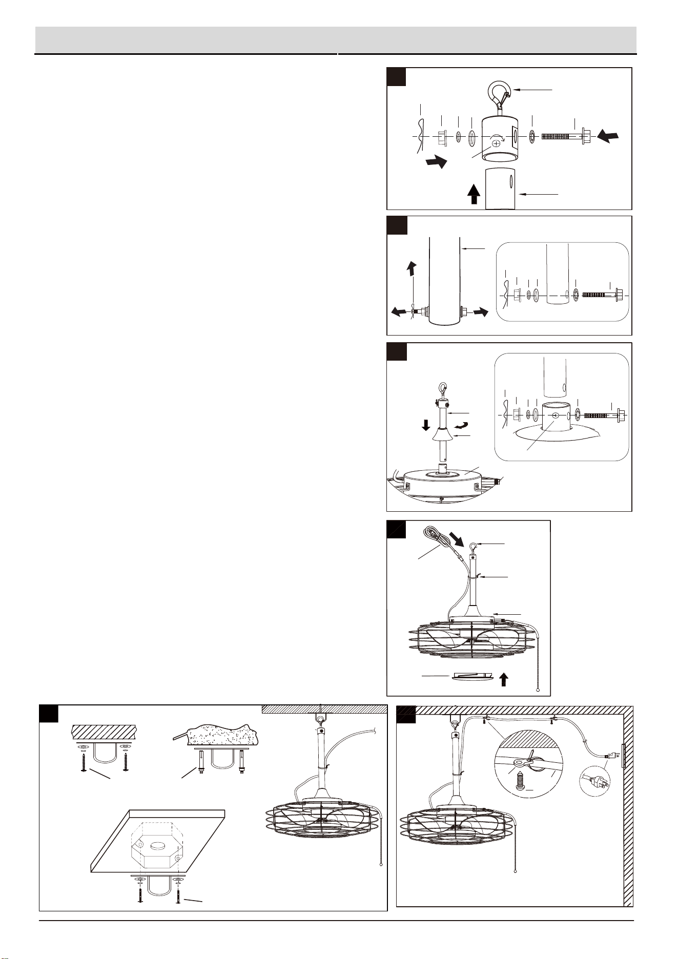
Assembly Instructions (continued)
2
C
B
F
J
E
2. The packaging contains 2 downrods, please choose an
appropriate downrod (C) to assemble with the hanger
buckle (B).
5. Secure the power cord (J) on the downrod (C) with cable tie
(H), then install the lamp shade (F) onto the LED housing.
6. Hanger bracket can install onto different locations, such as on
wood, cement ceiling and outlet box, shown as the diagram 6.
Attach the hanger buckle onto the hanger bracket.
7. Fix the cable ties (H) to the power cord (J), and use the wall
screws (I) to attach the cable ties (H) to the wall or the ceiling.
Plug into a grounded 3-prong outlet.
Once power is restored to the house, the fan is ready for use.
Place tooth washer (b) on the bolt (a), thread the hanger buckle
(B) holes to downrod holes, then secure with flat washer (c),
spring washer (d) and nut (e). Insert lock pin (f) into the bolt hole
until it snaps into place. Tighten the coupling screw (g) securing
the downrod (C).
1
2
3
4
Outlet Box
Wood
Cement
H
3
Wood screw
Cement anchor screw
Outlet box screw
6
7
I
6
a
b
c
d
e
f
3. Remove the lock pin (f), nut (e), spring washer (d), and flat
washer (c) from the downrod (C) in sequence. Loosen the
bolt (a) and tooth washer (b) from the downrod (C).
4. Insert the hanger buckle assembly through the coupling cover
(D) into the coupling. Ensure that the holes on the downrod (C)
align with the holes on the coupling. Insert the bolt (a) with the
tooth washer (b) through the coupling and the downrod (C).
Then, sequentially attach the flat washer (c), spring washer (d),
and nut (e) to the other end of the bolt (a) and tighten securely.
Insert the lock pin (f) into the bolt hole until it snaps into place.
Tighten the coupling screw (g) securing the downrod (C), and
slide the coupling cover (D) onto the fan body (E).
g
cd
e
f
a
b
C
cd
e
f
a
b
C
D
E
g
H
J
K
4
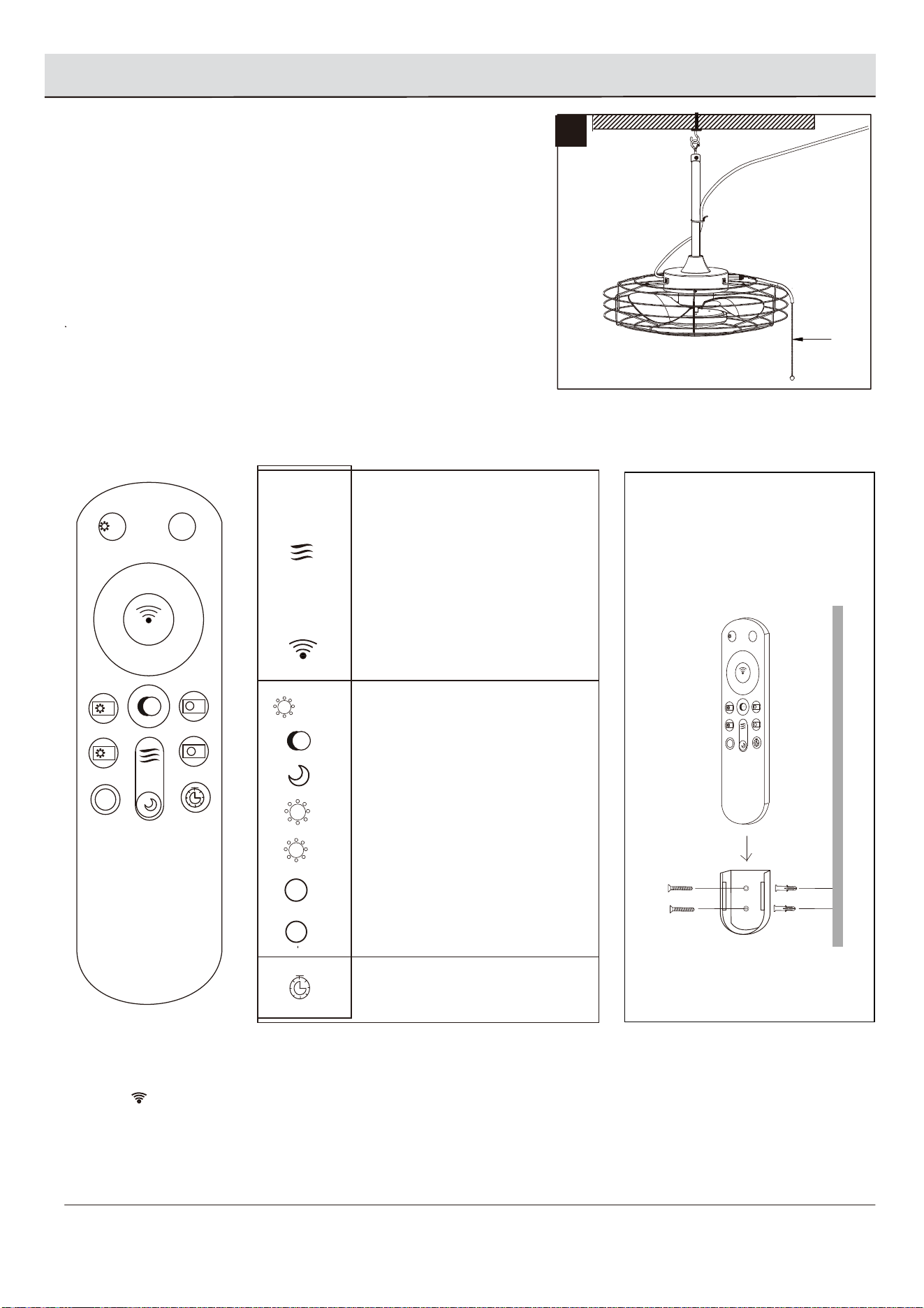
Operating Instructions
1
☆
F/R
-
K
-
K
+
+
SETUP
3
6
4
5
2
1
ALL OFF
ON
OFF
K
ALL OFF
1-6
FAN / OFF
F/R
-
+
K
-
K
+
☆
ON
OFF
SETUP
SETUP
Light&Fan all OFF
Fan Speed
Natural wind
Forward/Reverse Switch
Fan Off
Code Key
Light On/Off
Color temperature switching
Night light
Brightness -
Brightness +
Color Temperature+
Color temperature-
Fan Stop After 2 Hours
Setting the Airflow Speed
1. Pull Chain
Turn ON/OFF the fan and the light.
2. Remote control
Turn on the fan with pull chain, use the romote control to adjusting fan speed, lighting brightness and color temperature.
3. Code Matching
Press on the transmitter for 5 seconds to match the code on receiver (already installed in the fan body).
If it does not work, please turn off the circuit breaker or wall switch and try again. After matching, both transmitter
and receiver will remember the last code match.
☆
F/R
-
K
-
K
+
+
SETUP
3
6
4
5
2
1
ALL OFF
ON
OFF
K
Step1
Step2
Step3
Wall
Install the hold onto the wall by
using the (2) anchors and screws.
Put the transmitter into the hold
while it is not in use.
** Install (2) AAA batteries
(not included).
K
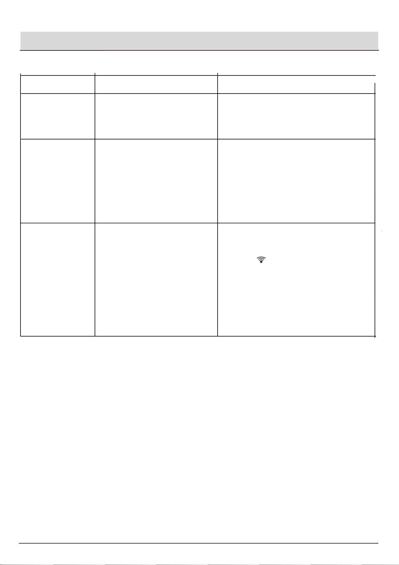
1. Fan does not move
.
Troubleshooting
5
SETUP
1. Turn off the power, then turn it on quickly
(within 10 seconds of turning the power on)
hold the keys for 5 seconds to match
code.
2. Insert new battery in battery compartment of
the transmitter.
3. If there are several fans in proximity, turn
power off to other fans and re-code the
remote.
1. Turn off power. Loosen the screws on the fan
housing and the front guard of the fan blades,
then tighten the blades.
2. Turn off power. Tighten the mounting bracket
to make sure it is securely mounted.
3. Lower or move fan to another place.
Extension downrod may be required.
1. Blades are loose.
2. Fan not securely mounted.
3. Fan too close to vaulted ceiling.
1. Power surge may have cleared
memory and transmitter needs to
be re-coded to the receiver.
2. Battery in transmitter needs to be
replaced.
3. Interference from another remote
control.
3. Remote control
does not work
2. Excessive wobbling
1. Turn power on or check fuse.
2. Turn power off. Check all connections.
1. Power is off or fuse is blown.
2. Bad wire connection.
Problem Possible Cause Corrective Action
6
The limited lifetime warranty covers this ceiling fan, for residential use by the original purchaser,
against defects in material or workmanship as follows:
If your Patriot Lighting Ceiling Fan motor fails at anytime during the lifetime of the original
purchaser due to defects in material or workmanship, we will provide a replacement part free of
charge.
If your fan blades, pull chain switch, reverses witch, or any accessory, except glass globes and
light bulbs, fails at any time within two years after the original date of purchase due to a defect in
material and workmanship, we will repairor, if we choose, replace the defective blades, switch,
or accessory free of charge, with the exception of take down/reinstallation services.
If the original purchaser ceases to own the fan, this warranty and any implied warranty, including
but not limited to any implied warranty of merchantability or fitness for a particular purpose,
become void.
This warranty and any implied warranty, including but not limited to any implied warranty of
merchantability or fitness for a particular purpose, do not cover glass globes, light bulbs, or
finish on any metal portions of the fan.
This warranty is in lieu of express warranties. The duration of any implied warranty of
merchantability or fitness for a particular purpose, with respect to any Patriot Lighting Ceiling
Fan motor, blades, switch, or accessories, is expressly limited to the period of the express
warranty set forth above for such motor, blades, switch, or accessories.
This warranty excludes defects, malfunctions, or failures of any Patriot Lighting Fan that are
caused by repairs by persons not authorized by us, use of parts or accessories not authorized
by us, mishandling, improper installation, modifications or damage to the fan while in your
possession, or unreasonable use, including failure to provide necessary maintenance.
To obtain service, contact the service department. You will be responsible for all insurance and
freightor other transportation charges to our factory or service center. A copy of sales receipt is
required in order to obtain service. We will return your fan freight prepaid. Your fan should be
properly packed to avoid damage in transit, for we will not be responsible for any such damages.
In no event shall Patriot Lighting Fan be liable for consequential or incidental damages.
Some states do not allow the exclusion or limitation of consequential or incidental damages, in
which case the above limitation or exclusion may not apply.
This warranty gives you specific legal rights and you may also have other rights which vary from
state to state.
Limited Lifetime Warranty
