Loading ...
Loading ...
Loading ...

281, 282, 284
Users Manual
Introduction
Both internal and external sum can be selected; summing can be used to add noise to a
waveform, for example, or to add two signals for DTMF (dual tone multiple frequency)
testing.
External sum can be applied to any or all channels. Internal sum uses the previous
channel as the source, so that for example channel 2 can be added into channel 3; internal
sum is not available on channel 1 or on a single channel instrument.
Summing shares some of the generator’s inter-channel resources with the modulation
modes; as a result neither internal nor external sum can be used with internal modulation
but external modulation is still possible with sum.
To better understand the constraints, the following sections (and chapter 11, Modulation)
should be read with reference to the block diagrams in appendix F. These show the
control signals in a single channel and the inter-channel connections.
These diagrams also show the inter-channel trigger connections described in chapter 7,
Triggered Burst and Gate; in general, inter-channel triggering is possible simultaneously
with summing.
External Sum
In sum mode an external signal applied to the SUM input is summed with the
waveform(s) on the specified channel(s). The same sum input signal can be used at
different amplitudes with each of the channels with which it is summed.
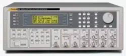
Pressing the SUM key calls the SUM set-up screen:
SUM source: ext
ratio: 0dB
CH2 +2.00 Vpp
Pressing the source soft-key steps the sum sources between off, external and
CHx where x is the number of the previous channel.
With ext selected the screen is as shown above. The level of the SUM can be adjusted
independently for the selected channel by pressing the ratio soft-key; use the rotary
knob or cursor keys to set the SUM input attenuation for that channel from 0 to –50 dB in
10 dB steps. This facility permits the same SUM signal to be used at different levels with
each channel.
Clipping will occur if the sum input level attempts to drive the channel amplitude above
the maximum 20 V p-p open-circuit voltage. However, the relationship between the
SUM input and the maximum summed output depends not only on the sum input level
but also on the channel's own amplitude setting. This is because the sum input is applied
to the amplifier chain prior to the output attenuators. The amplifier itself is controlled
over a limited range (approximately10 dB) and the full amplitude range of the channel is
achieved by switching in up to five 10 dB attenuation stages. The summed output cannot
exceed the maximum of the range within which the channel output has been set by choice
of amplitude setting. Whereas with internal sum the generator gives warnings when the
combination of sum input and amplitude would cause waveform clipping (see Internal
Sum below), it is the responsibility of the user to observe the waveforms when using
external sum and to make adjustments if the waveform is clipped. Note that it is not
12-2
1.888.610.7664 sales@GlobalTestSupply.com
Fluke-Direct.com
Loading ...
Loading ...
Loading ...