Loading ...
Loading ...
Loading ...
281, 282, 284
Users Manual
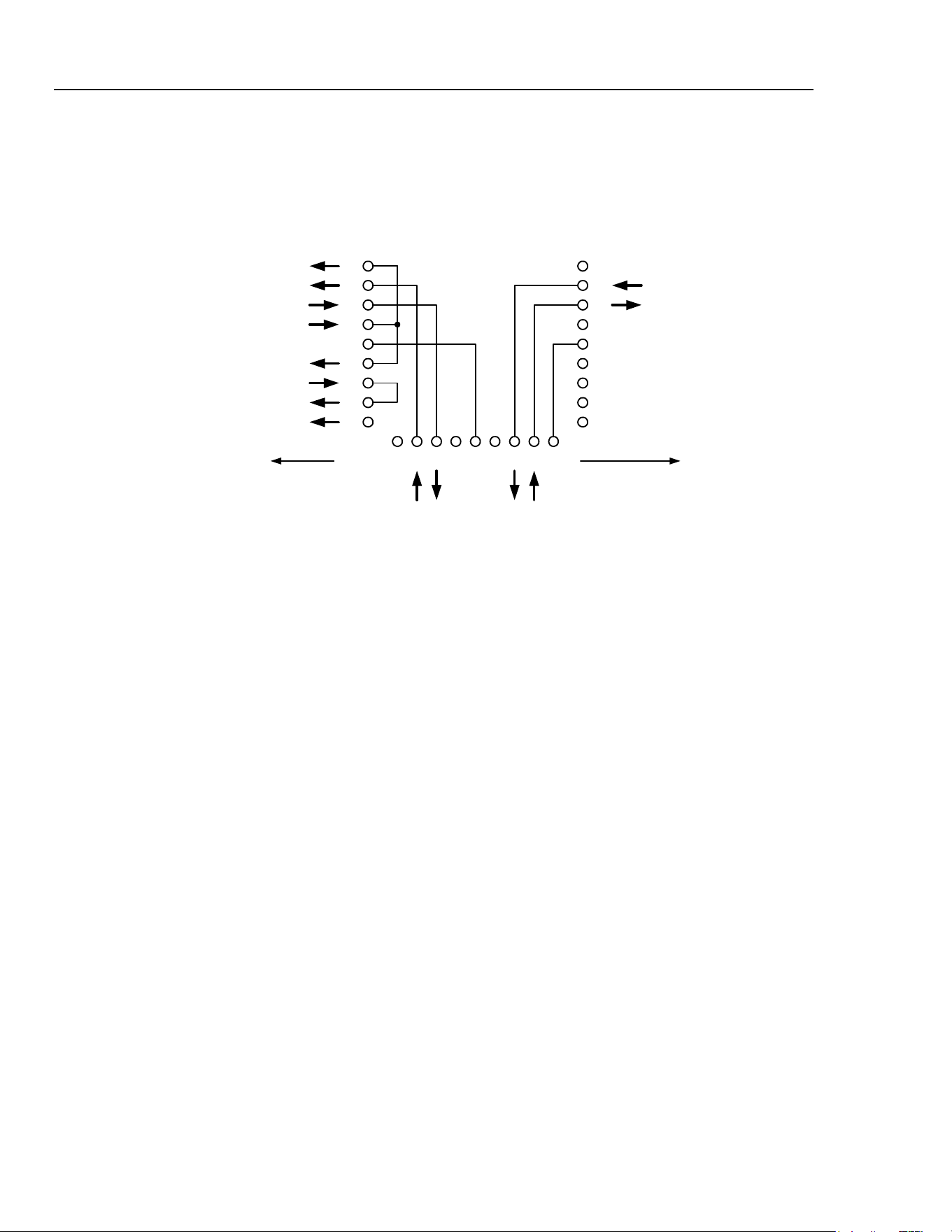
The daisy chain consists of the transmit data (TXD), receive date (RXD) and signal
ground lines only. There are no control/handshake lines. This makes XON/XOFF
protocol essential and allows the inter-connection between instruments to contain just 3
wires. The wiring of the adaptor cable is shown below:
RX
1
2
3
4
5
6
7
8
9
1
2
3
4
5
6
7
8
9
DCD
RX
TX
DTR
GND
DSR
RTS
CTS
RI
TX
GND
9-WAY D
MALE
9-WAY D
FEMALE
123456789
TX RX TXIN RXOUT
UP TOWARDS
CONTROLLER
DOWN TOWARDS
OTHER INSTRUMENTS
INSTRUMENT
CONNECTOR
9-WAY D
MALE
shb0011f.emf
Figure 16-3. RS232 Daisy-Chain Connector Wiring
All instruments on the interface must be set to the same baud rate and all must be
powered on, otherwise instruments further down the daisy chain will not receive any data
or commands.
The other parameters are fixed as follows:
Start Bits: 1
Data Bits: 8
Parity: None
Stop Bits: 1
RS232 Character Set
Because of the need for XON/XOFF handshaking it is only possible to send ASCII coded
data; binary blocks are not allowed. Bit 7 of ASCII codes is ignored, i.e. assumed to be
low. No distinction is made between upper and lower case characters in command
mnemonics and they may be freely mixed. The ASCII codes below 20H (space) are
reserved for addressable RS232 interface control. (In this manual 20H means 20 in
hexadecimal.)
Addressable RS232 Interface Control Codes
All instruments intended for use on the addressable RS232 bus use the following set of
interface control codes. Codes between 00H and 1FH which are not listed here as having
a particular meaning are reserved for future use and will be ignored. Mixing interface
control codes inside instrument commands is not allowed except as stated below for CR
and LF codes and for XON and XOFF codes.
When an instrument is first powered on it will automatically enter the non-addressable
mode. In this mode the instrument will not respond to any address commands. This
allows the instrument to function as a normal RS232 controllable device. The non-
addressable mode may be locked by sending the Lock Non-Addressable mode control
code, 04H. The controller and instrument can now freely use all 8 bit codes and binary
16-4
1.888.610.7664 sales@GlobalTestSupply.com
Fluke-Direct.com
Loading ...
Loading ...
Loading ...