Loading ...
Loading ...
Loading ...
Tone Mode
Tone Switching Source 8
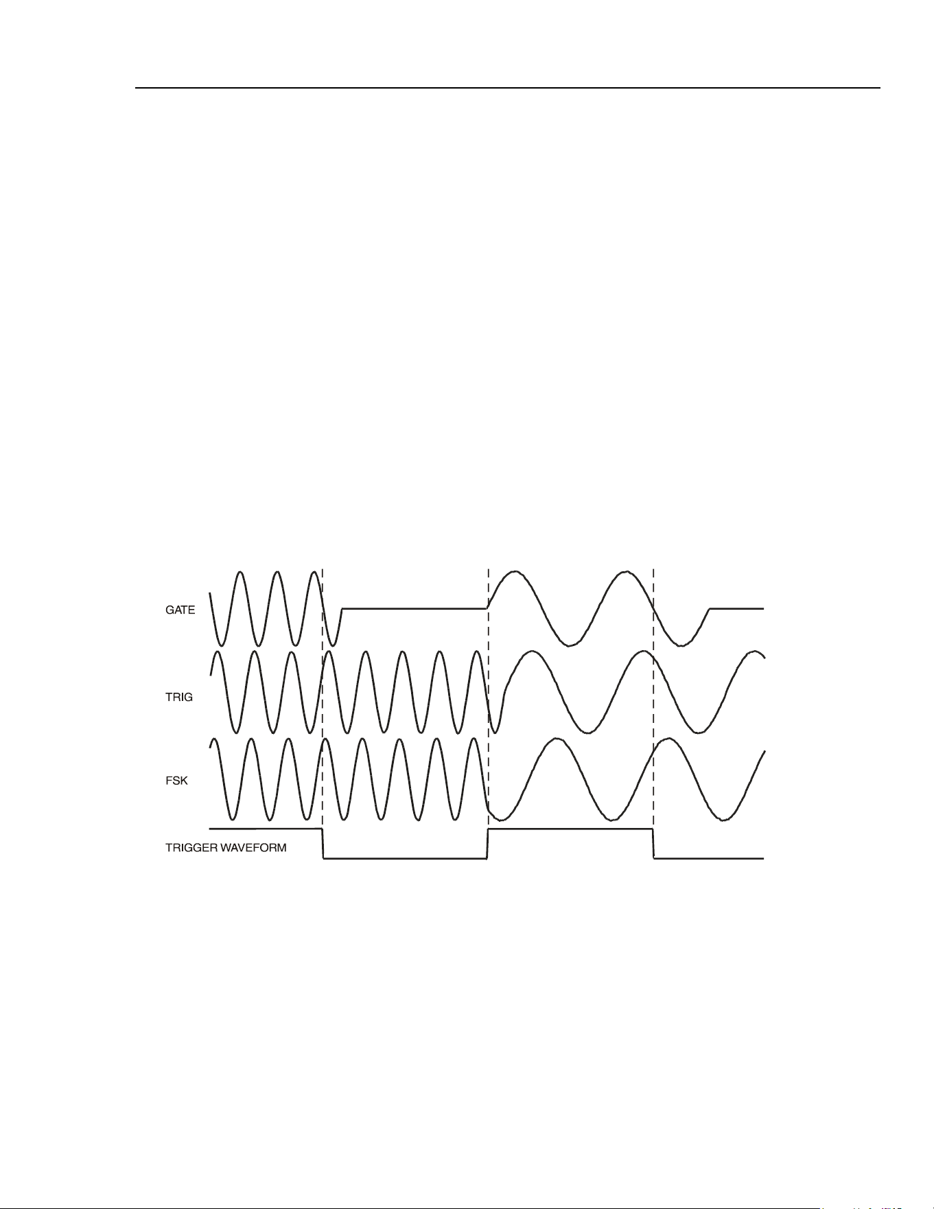
Thus the difference between triggered and gated tone changes is that in triggered mode
the signal changes phase continuously from one frequency to the next at the waveform
zero-crossing point immediately after the trigger signal, whereas in gated mode there can
be an off (no signal) period between successive frequencies while the gate signal is not
true.
With type set to fsk the frequency changes instantaneously (and phase-
continuously) at each occurrence of the signal edge specified in the source and
slope fields on the TRIGGER IN screen, without completing the current waveform
cycle; this is true FSK (frequency shift keying) tone switching.
The following diagrams demonstrate the differences between trigger, gate and FSK tone
switching for a list of two frequencies switched by a square wave (positive slope
specified on the TRIGGER IN set-up).
The maximum recommended tone frequencies and trigger/gate switching frequencies for
the three modes are as follows:
GATE: Maximum tone frequency 50 kHz;
maximum switching frequency < lowest tone frequency.
TRIGGER: Maximum tone frequency 50 kHz;
maximum switching frequency 1 MHz.
FSK: Maximum tone frequency 1 MHz;
maximum switching frequency 1 MHz.
shb0008f.emf
Figure 8-1. Tone Waveform Types
Tone Switching Source
The signal which controls the frequency switching is that set by the source soft-key
on the TRIGGER IN set-up screen. The slope field on the same screen sets the
active polarity of that signal; when set to positive the rising edge of the trigger
signal is active or the high level of the gating signal is true. The reverse is true for a
negative setting. The signal selections available on the source soft-key are the
internal trigger generator, an external trigger input, the front panel MAN TRIG key, a
remote command and, for multi-channel instruments, the trigger output from an adjacent
channel. A full explanation for each of these can be found in chapter 7, Triggered Burst
and Gate.
8-3
1.888.610.7664 sales@GlobalTestSupply.com
Fluke-Direct.com
Loading ...
Loading ...
Loading ...