
Loading ...
Loading ...
Loading ...
8
SET-UP
NOTE: This Operator’s Manual covers several models. Tractor
features may vary by model. Not all features in this manual are
applicable to all tractor models and the tractor depicted may
differ from yours.
NOTE: All references in this manual to the left or right side and
front or back of the tractor are from the operating position only.
Exceptions, if any, will be specified.
PREPARATION
Manually Moving the Tractor
1. Engage the transmission bypass rod to move the tractor
manually without starting it. The transmission bypass rod is
located on the rear of the tractor, on the frame. Engage the
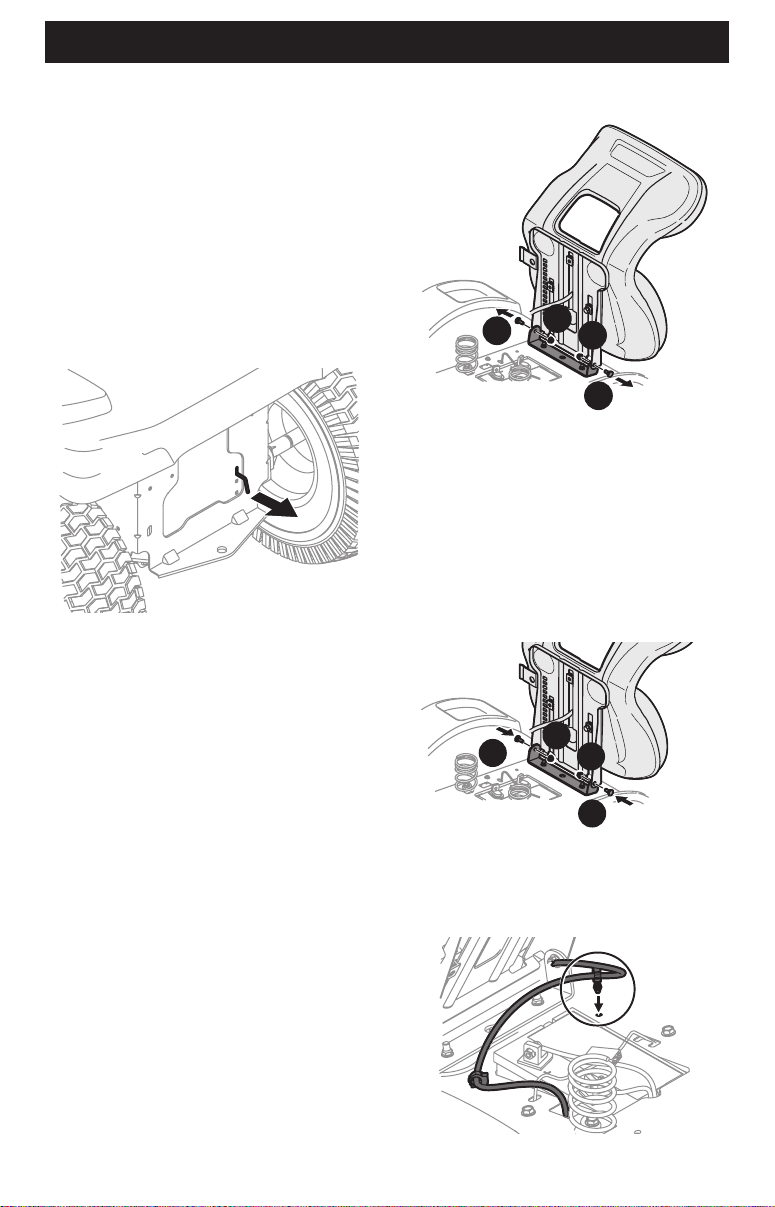
bypass rod by pulling out (Figure 1).
Figure 1
NOTE: If the tractor will not move or does not move freely when
pushing check if the hydrostatic bypass rod is fully open or the
brake is engaged.
NOTE: The transmission will NOT engage when the hydrostatic
bypass rod is pulled out. Return the rod to its disengaged
position prior to operating the tractor.
2. Disengage the transmission bypass rod by pushing the rod
back in after moving the tractor (Figure 1).
Install Operator’s Seat (If necessary)
To install the seat proceed as follows:
NOTE: The seat is shipped with the seat switch and seat
pan attached.
1. Cut any straps securing the seat assembly to the tractor.
Remove any packing material.
NOTE: Be careful not to cut the wiring harness connecting the
seat and the seat switch.
2. Remove the two shoulder bolts (a) and flange lock nuts (b) in
the seat pan (Figure 2).
a
a
b
b
Figure 2
3. Rotate the seat into position and slide a Phillips screwdriver
through one of the seat-securing holes and seat bracket
for alignment.
4. With the previously removed shoulder bolts (a) and flange
lock nuts (b) secure one side of the seat and seat bracket.
While supporting the seat, remove the Phillips screwdriver
and secure the other side of the seat. Be careful not to crimp
or damage the wire harness while installing the seat (Figure
3). Torque to 84-103 in-lbs (9-12 N-m).
a
a
b
b
Figure 3
5. Using the harness clip attached to the harness, secure the
excess wire to the fender by snapping the harness clip in
place (Figure 4).
Figure 4
Loading ...
Loading ...
Loading ...