Loading ...
Loading ...
Loading ...
33
PRODUCT CARE
Standard Blade System (If equipped)
1. With the deck removed gently flip the deck over to expose
its underside.
2. Line up the hole in the center of the blade with the star-
shaped retainer at the bottom of the spindle assembly and
slide the blade into place.
3. Place a block of wood between the deck housing baffle
and the cutting blade to act as a stabilizer (Figure 46 on
page 32).
4. Thread on the hex flange nut to secure the blade to the
spindle assembly.
5. Use a torque wrench to tighten the blade spindle hex flange
nut to 70-90 ft-lbs (95-122 N-m).
6. Re-install the deck (refer to Changing the Deck Belt and
Reinstalling the Deck in this section).
NOTE: When replacing or reinstalling the blade, be sure to install
the blade with the side of the blade marked ‘‘Bottom’’ (or with a
part number stamped in it) facing the ground.
Standard Blade System with S-Blades
(If equipped)
1. With the deck removed gently flip the deck over to expose
its underside.
2. When re-installing blades, be sure of the following (Figure 47
on page 32):
a. Blades (b) are installed so that wings are pointing upward
toward the top of the deck.
b. Washer (d)* is placed between bottom of blade (b) and
hex nut (a).
IMPORTANT! Align “S” shaped cutout with matching “S” shape
on spindle for secure fit.
3. Tighten hex nuts (a) to 70-90 ft-lbs (95-122 N-m) (Figure 47
on page 32).
4. Re-install the deck (refer to Changing the Deck Belt and
Reinstalling the Deck in this section).
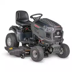
SHARPENING THE BLADE
1. To properly sharpen the cutting blades, remove equal
amounts of metal from both ends of the blades along the
cutting edges, parallel to the trailing edge, at a 25° to 30°
angle. Always grind each cutting blade edge equally to
maintain proper blade balance (Figure 51).
Figure 51
2. Test the blade’s balance using a blade balancer. Grind metal
from the heavy side until it balances evenly.
WARNING
A poorly balanced blade will cause excessive vibration,
may damage the tractor, and/or result in personal injury.
CHANGING THE DECK BELT AND
REINSTALLING THE DECK
CAUTION
The V-belts found on your tractor are specially
designed to engage and disengage safely. A substitute
(non-OEM) V-belt can be dangerous by not disengaging
completely. For a properly working tractor, use factory
approved belts.
All belts on your tractor are subject to wear and should be
replaced if any signs of wear are present. To change or replace the
deck belt on your tractor, proceed as follows:
1. Remove the deck as instructed earlier in this section under
Deck Removal.
2. Loosen, but do not remove, the hardware on the right and
left idler pulley.
NOTE: On some decks it may be necessary to remove the spindle
covers to remove and/or install the new belt. To remove the
spindle covers, remove the screws securing them to the deck.
3. Carefully remove the belt from around the idler pulleys and
the spindle pulleys.
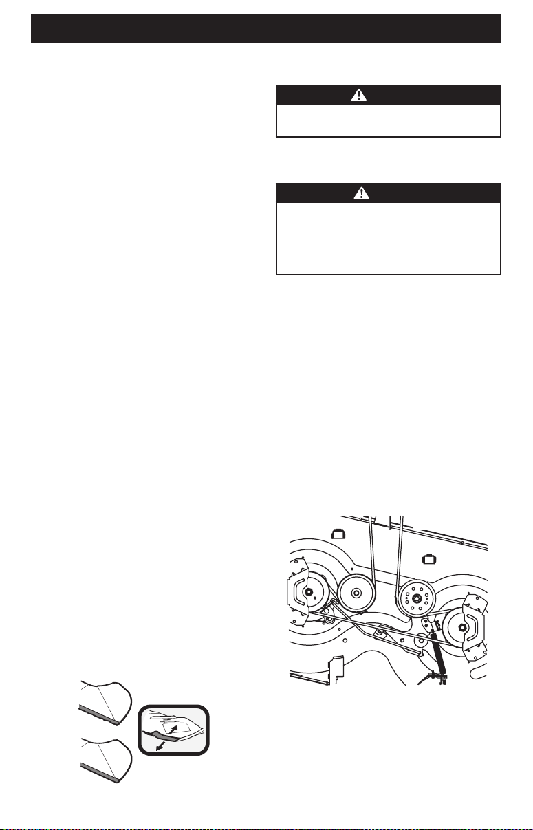
4. Route the new belt as shown in the applicable figure below.
See Figure 52 (42 inch decks) and page 34 for Figure 53 (46
inch decks) and Figure 54 (50 and 54 inch decks).
42 Inch Decks
Figure 52
Loading ...
Loading ...
Loading ...