Loading ...
Loading ...
Loading ...
29
PRODUCT CARE
REMOVING THE TRACTOR FROM STORAGE
1. Check the engine oil.
2. Fully charge the battery and inflate the tires to the
recommended pressure. See tire side wall for proper tire
inflation pressure.
3. Fill the fuel tank with clean, fresh gasoline.
4. Start the engine and allow to idle for a few minutes to ensure
engine is operating properly.
5. Drive the tractor without a load to make certain all the tractor
systems are functioning properly.
ADJUSTMENTS
Deck Leveling
If the cutting deck appears to be mowing unevenly, leveling
adjustments can be performed.
WARNING
If the tractor has been recently run, the engine, muffler,
and surrounding metal surfaces will be very hot and can
cause burns to the skin. Let the engine cool for at least
five minutes. Exercise caution to avoid burns.
NOTE: Check the tractor’s tire pressure before performing any
deck leveling adjustments. Refer to Tires in this section for
information regarding tire pressure.
Leveling the Deck (Side-to-Side)
1. With the tractor parked on a firm, level surface, place the
deck lift lever in the middle position and rotate both blades
so that they are perpendicular with the tractor.
2. Measure the distance from the outside of the left blade tip
to the ground and the distance from the outside of the right
blade tip to the ground. Both measurements taken should be
equal. If they are not, proceed to the next step.
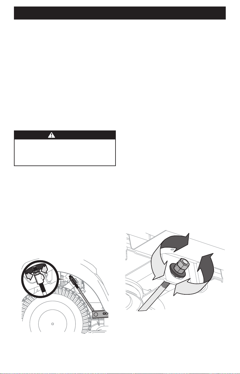
3. Under the rear fenders inside the wheels there is a lift
adjustment rod for each side of the deck (Figure 36).
Figure 36
4. Minor side-to-side adjustments should be made using
primarily the left adjustment rod.
5. To raise the left side of the deck, loosen the upper nut on the
end of the lift rod, then turn the lower nut clockwise. When
the proper adjustment is achieved, tighten the upper nut to
secure in place. To lower the left side of the deck, loosen the
upper nut on the end of the lift rod, then turn the lower nut
counter-clockwise. When the proper adjustment is achieved,
tighten the upper nut to 25-30 ft-lbs (33.9-40.7 N-m) to
secure in place.
6. The deck is properly leveled when both blade tip
measurements taken earlier are equal.
Leveling the Deck (Pitch/Front-To-Rear)
The front of the deck is supported by a stabilizer bar that can be
adjusted to level the deck from front to rear. The front of the deck
should be 1⁄4-3⁄8 inch (6.35 mm-9.5 mm) lower than the rear of
the deck. Adjust if necessary as follows:
1. Park the tractor on a firm, level surface, place the deck lift
lever in the middle position and rotate the blade nearest the
discharge chute so that it is parallel with the tractor.
2. Measure the distance from the front of the blade tip to the
ground and the rear of the blade tip to the ground. The front
of the deck should be between 1⁄4-3⁄8 inch (6.35 mm-9.5
mm) less than the rear of deck.
3. Determine the approximate distance necessary for proper
adjustment and proceed, if necessary.
4. To raise the front of the deck, loosen the outer nut then
tighten (thread inward) the inner nut against the front
hanger bracket (Figure 37). When proper adjustment is
achieved, re-tighten the outer nut to 25-30 ft-lbs (34 mm-
40.7 N-m).
Figure 37
5. To lower the front of the deck, loosen the outer nut then
loosen (thread outward) the inner nut, away from the front
hanger bracket (Figure 37). When proper adjustment is
achieved, re-tighten the outer nut.
Loading ...
Loading ...
Loading ...