
Loading ...
Loading ...
Loading ...
34
PRODUCT CARE
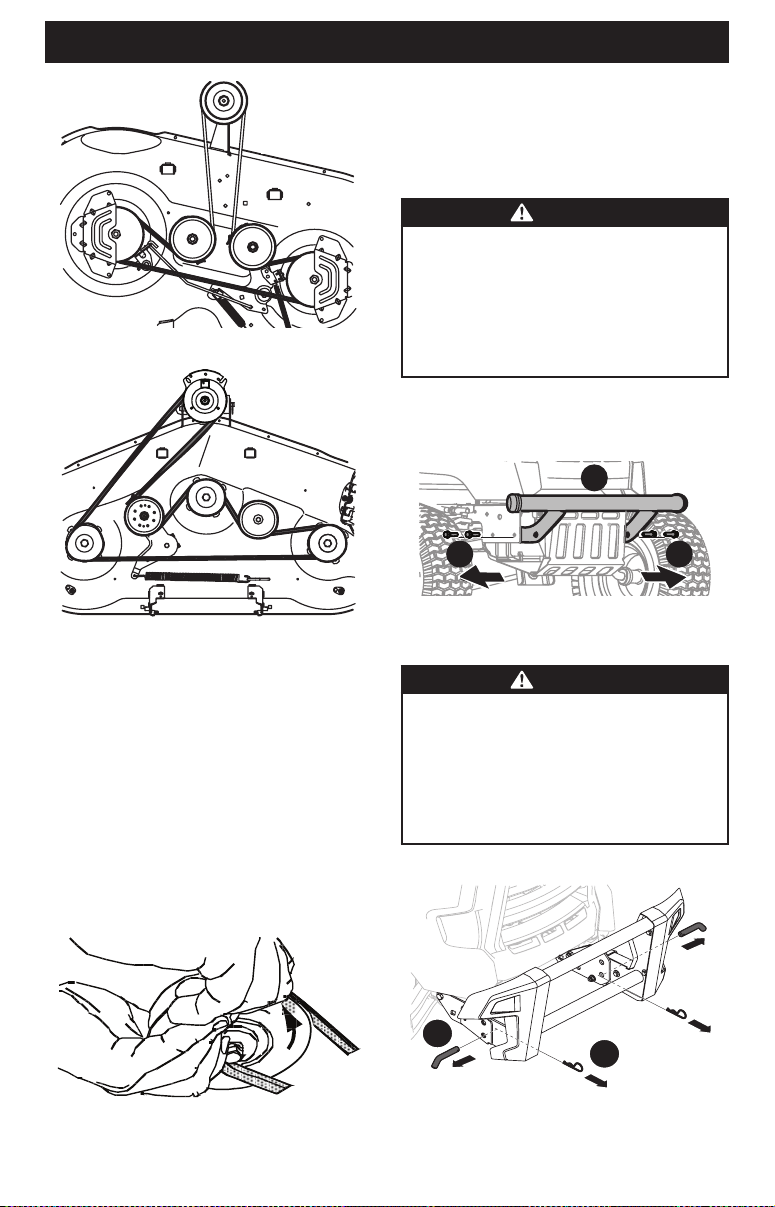
46 Inch Decks
Figure 53
50 and 54
Inch Decks
Figure 54
NOTE: Use a 3⁄8 inch drive ratchet wrench as instructed in earlier
steps when routing the new belt to pivot the drive pulley.
5. Ensure that the belt is routed properly along the idler pulleys
and inside the belt keepers and retighten idler pulleys, if
loosened earlier. Torque to 256-313 in-lbs (29-35 N-m).
6. Remount the spindle covers if removed earlier.
7. Re-install the deck making sure the belt remains routed
around the pulleys as instructed.
8. On manual PTO units, re-install the engine pulley keeper rod
and the PTO cable.
9. Pull the right side of the belt and place the narrow “V” side of
the belt into the PTO pulley (Figure 55).
Figure 55
10. While holding the belt and pulley together, rotate the pulley
to the left. Continue holding and rotating the pulley and belt
until the belt is fully rolled into the PTO pulley.
REMOVING THE FRONT BUMPER
IF EQUIPPED
WARNING
Disengage the PTO, engage the brake lock, and stop
the tractor engine before performing any maintenance
procedures. Place the tractor on a firm and level surface
before beginning installation or removal procedures.
The exhaust system and surrounding areas are HOT. To
avoid personal injury, allow the tractor to cool before
beginning any installation or removal procedures.
1. Remove the four hex screws (a) securing the front bumper in
place (Figure 56).
2. The front bumper (b) may now be removed.
a a
b
Figure 56
REMOVING THE BRUSH GUARD IF EQUIPPED
WARNING
Disengage the PTO, engage the brake lock, and stop
the tractor engine before performing any maintenance
procedures. Place the tractor on a firm and level surface
before beginning installation or removal procedures.
The exhaust system and surrounding areas are HOT. To
avoid personal injury, allow the tractor to cool before
beginning any installation or removal procedures.
1. Remove two cotter pins, and then pull the pins (Figure 57).
1
2
Figure 57
Loading ...
Loading ...
Loading ...