Loading ...
Loading ...
Loading ...

SDG7000A User Manual
WWW.SIGLENT.COM 21 /
133
6.3 Connecting to External Devices/Systems
6.3.1 Power supply
The standard power supply for the instrument is 100~240 V, 50/60 Hz. Please use the power
cord provided with the instrument to connect it to AC power.
6.3.2 Signal output
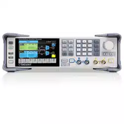
The 4 BNC terminals on the front panel are analog signal output ports.
The two left terminals are CH1 outputs, which can also be used as I outputs for baseband I/Q or
IF (Intermediate Frequency) outputs. The two right terminals are CH2 outputs, which can also
be used as Q outputs for baseband I/Q.
When the channel output is defined as differential, the right "+" and left "-" are used. When the
channel output is defined as single-ended, it is output from the "+" terminal.
The CH1/CH2 outputs do not support a floating ground. Please ensure that the
ground on the receiver side is of equal potential to the ground of this device.
6.3.3 LAN
Connect the LAN port on the rear panel to an active network with a standard ethernet network
cable terminated with an RJ45 connector.
Use a network cable to connect the LAN port on the rear panel of the unit to a network device.
Follow the steps below to set LAN connection:
Utility > Interface > LAN Settings
For more information on LAN settings, please refer to the section " LAN Settings".
The instrument is integrated with WebSever and supports direct access control via a browser.
See the section "
Web
Browser" for more information.
6.3.4 USB Peripherals
Connect a USB storage device (FAT32 format) to one of the USB host ports for data transfer, or
connect USB mouse/keyboard to one of the USB host ports for controlling the instrument.
6.3.5 USB device interface
The instrument supports remote control by connecting the instrument to the host computer via
the USB Device port. See the chapter "Remote control" for more information.
6.3.6 Reference clock input/output
When the instrument is using an external clock source, the 10 MHz reference clock is input
from the 10MHz IN port located on the rear panel. The 10 MHz OUT port outputs a 10 MHz sine
wave reference clock, which is synchronized with the active clock source no matter what the
clock source is.
Loading ...
Loading ...
Loading ...
