Loading ...
Loading ...
Loading ...

©2021 Sharp NEC Display Solutions, Ltd. Page 74 of 86
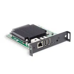
8. Locate the U.FL antenna receptacle connector on the Compute Module near the silver
wireless module with the FCC and CE engraving.
Note: If needed, the FCC / ISED ID of the Compute Module is engraved onto the wireless module.
Figure 12.3-8 U.FL antenna receptacle connector on the Compute Module
9. Carefully align the antenna cable connector over the antenna receptacle connector on
the Compute Module, with the coax cable routed over the corner of the Compute
Module as shown.
Figure 12.3-9 U.FL antenna connector alignment of receptacle and cable
Loading ...
Loading ...
Loading ...