Loading ...
Loading ...
Loading ...

©2021 Sharp NEC Display Solutions, Ltd. Page 70 of 86
12.2 Parts identification
• External antenna with SMA female connector.
• Coax cable with SMA male connector and U.FL connector.
• Hex nut, knurled washer, and compression washer.
Figure 12.2-1 Antenna parts
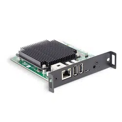
• U.FL antenna connector on the Compute Module
• WF_nDisable wireless function header pins
• EEPEOM_nWP header pins
• LED1007 Wi-Fi enable LED status indicator
Figure 12.2-2 Compute Module and Interface Board
Loading ...
Loading ...
Loading ...