Loading ...
Loading ...
Loading ...

©2021 Sharp NEC Display Solutions, Ltd. Page 59 of 86
8 Troubleshooting
Problem: No video when switching to the Compute Module input
Solutions:
• Confirm that the indicator LED on the side of the Compute Module Interface Board is red or
orange. If the indicator is not on, then there is no power to the Interface Board, or the Compute
Module is not installed or not installed correctly.
• On the SLOT COMPUTE MODULE POWER CONTROL menu of the OSD, confirm
that POWER SUPPLY is set to ON.
• Check that the Compute Module 4 is correctly seated and snapped into the socket on
the Interface Board.
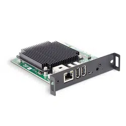
• Check that the BOOT MODE switch on the side of the Interface Board is in the correct position.
In normal operating mode, the switch is positioned away from the USB Micro-B connector.
Note that the postion of the switch is only recognized when power is initially applied to the
Compute Module. Changing the position of the switch after power is applied to the Compute
Module does not affect its operating/boot mode.
Figure 8-1: BOOT MODE switch - normal mode
• Confirm that a valid OS image has been written to the Compute Module.
• Confirm that the Compute Module input on the display is currently selected.
• Confirm that a valid video resolution has been configured on the Compute Module. Note that
4096x2016 @ 60Hz is currently not supported. Use the native resolution of 3840x2160 @ 60Hz
or 30Hz instead.
Problem: “RPi Boot” is unable to detect the Compute Module
If the Rpiboot window stays open and displays only “Waiting for BCM2835/6/7/2711…” then the
Compute Module has not been detected.
Solutions:
Loading ...
Loading ...
Loading ...