Loading ...
Loading ...
Loading ...
bly
_ 2
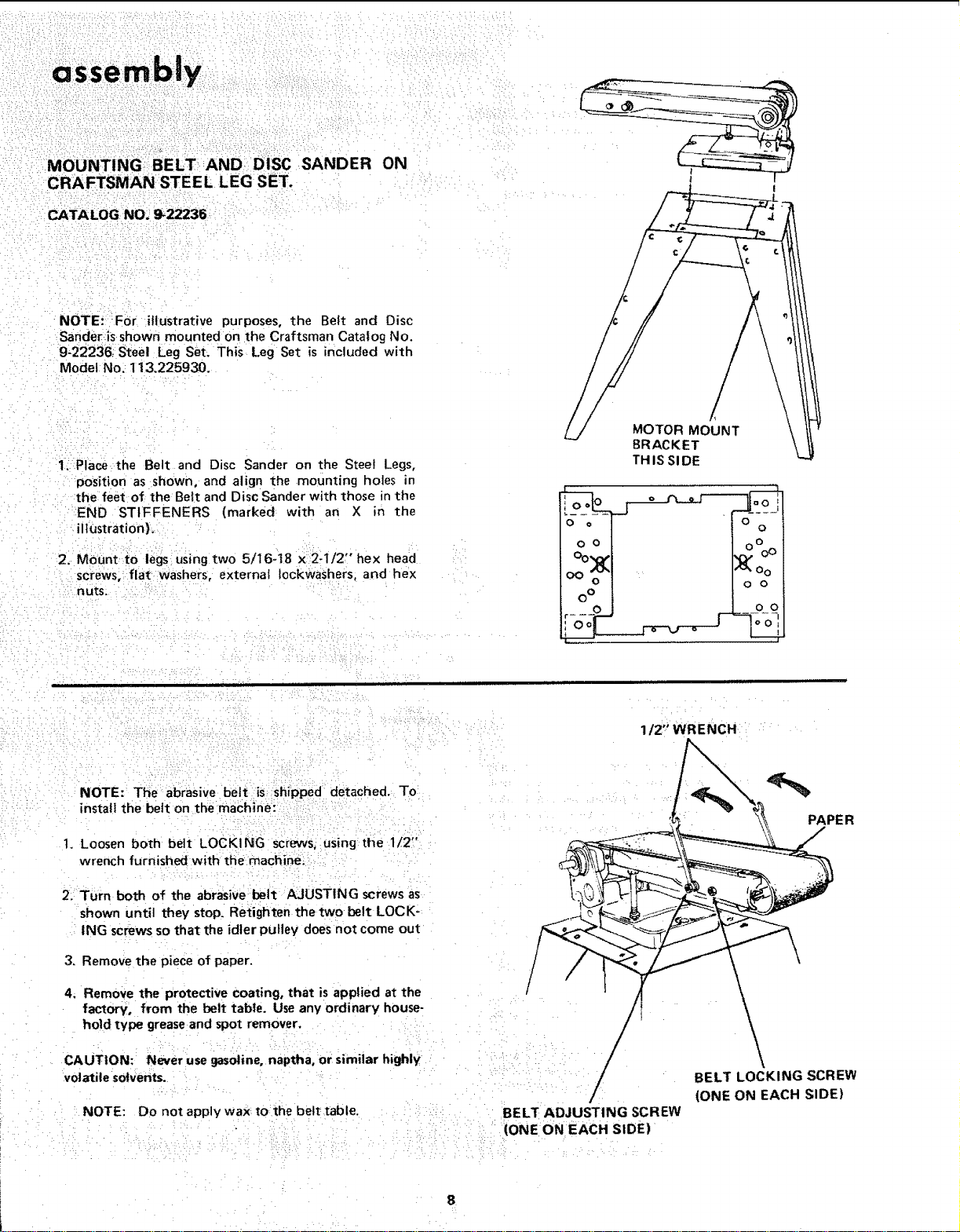
MOUNTING BELT AND DiSC SANDER ON
CRAFTSMAN STEEL LEG SET.
CATALOG NO,_ _22236-
NOTE!: =FOr illustrative purposes, the Belt and Disc
Sander=isshown mounted on the Craftsman Catalog No.
9-22236; Steel Leg set. This Leg Set is included with
Model No. 113.225930.
1_ Place the Belt and Disc Sander on the Steel Legs,
position as shown, and align the mounting holes in
the feet of the Belt and Disc Sander with those in the
END STIFFENERS (marked with an X in the
ilhJstration}.
2, MOunt to legs using two 5/I6-t8 x 2-1/2" hex head
screws, flat washerS, external fockwaShers, and hex
nuts.
/
MOTOR MOUNT
BRACKET
TH IS SI DE
1/2" WRENCH
NOTE: The abrasive belt is shipped detached. To
install the belt on the machine:
t. Loosen both belt LOCKING screws, using the 1/2"
wrench furnished with tt_e machine;
2. Turn both of the abrasive belt AJUSTING screws as
shown until they stop. Retighten the two belt LOCK-
ING screws so that the idler pulley does not come out
3. Remove the piece of paper.
4. Remove the protective coating, that is applied at the
factory, from the belt tabte. Useany ordinary house-
hold type greaseand spot remover.
CAUTION: Never use gasoline, naptha, or similar highly
volatile solvents.
NOTE: Do not apply wax tothe belt table.
/
BELT ADJUSTI NG SCREW
(ONE ON EACH SIDE)
PAPE R
BELT LOCKING SCREW
(ONE ON EACH SIDE)
Loading ...
Loading ...
Loading ...