Loading ...
Loading ...
Loading ...
know your beret
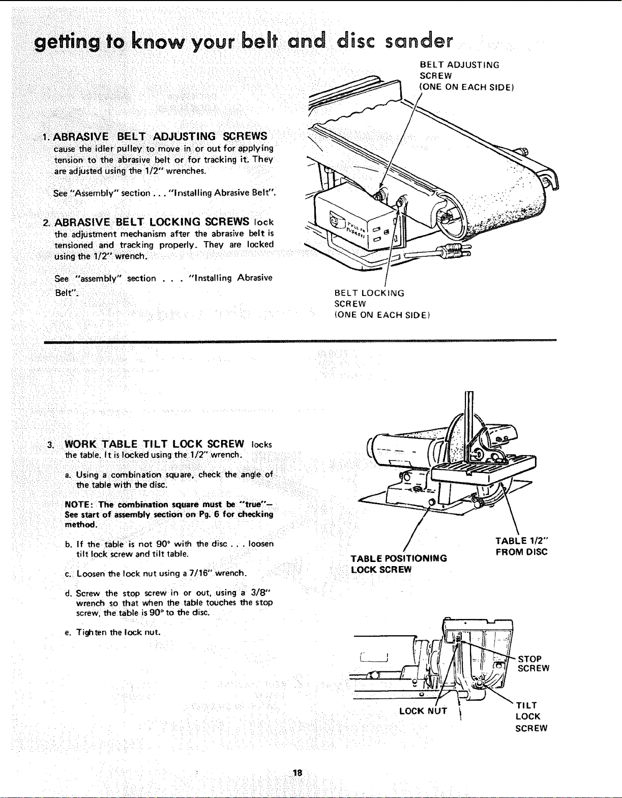
I_ AB _/E::BELT :ADJUSTING SCREWS
:catJse :dier pUiiey:i to:m0ve in::0r:out for appiylng
ter_sion:to theab_asive heft or for tracking it: They
are adjusted using the 112" wrenches,
see _'Assembly" section... "1 nsta!ling Abrasive Belt".
2. ABRASIVE BELT LOCKING SCREWS lock
the adjustment mechanism after the abrasive belt is
tensioned an,d tracking properly. They are locked
USihg the i/2': :wrench.
See "assembly" section . . . "Installing Abrasive
Belt".
\
s n er
BELT ADJUSTING
SCREW
(ONE ON EACH SIDE)
/
BELT LOCKING
SCREW
(ONE ON EACH SIDE)
i i ijjl i ] i _,
.: 3, ¸ WORK TABLE TILT LOCK SCREW locks
l_e table. It islocked using the 1/2" wrench.
a; Using a combination square, check the angle.of
the table witch the disc:
NOTE: The combination square must be "'true"--
See start of assembly section on Pg; 6 for checking
method.
b. If the table is not 90 ° with the disc ... loosen
tilt lock screw and tilt table,
c, Loosen the lock nut using a 7/16" wrench.
d. Screw the stop screw in or out, using a 318"
wrench so that when the table touches the stop
screw, the table is 90 ° to the disc,
e. Tighten the lock nut.
TABLE POSITIONING
LOCK SCR EW
TABLE 1/2"
FROM DISC
LOCK NUT
STOP
SCREW
TI LT
I LOCK
SCR EW
Loading ...
Loading ...
Loading ...