Loading ...
Loading ...
Loading ...
CONTENTS
Installing Belt Dust Trap .... . .. .............. 16
: : Imtalling:Backst0 p , y:=:..:..;... ...... ... ...... 17
GETTINGTO KNOW YOUR SANDER . : .... : ..... 17
Belt Adjusting Screws ....................... 18
Belt Locking:Screws ......................... 18
WorkTable Tile LOck Screw .................. 18
Backstop Lock Screw ........................ 19
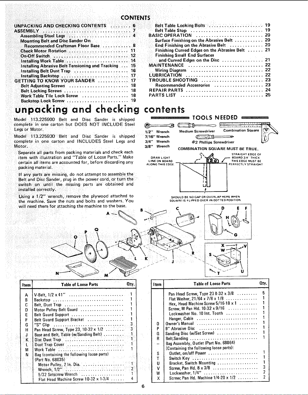
unpacking and checking
Model 113.225900 Belt and Disc Sander is shipped
complete inone carton but DOES NOT INCLUDE Steel
Legs or M0tor.
Model: t13i225930 Belt and Disc Sander is shipped
complete in one carton and INCLUDES Steel Legs and
Motor,
Separate aif parts from packing materials and check each
item With illustration and 'q'able of Loose Parts," Make
certain all items are accounted for, before discarding any
pack ing material.
If any parts are missing, do not attempt to assemble the
Belt and Disc Sander, plug in t'he power cord, or turn: the
switch on until the missing parts are obtained and
installed correctly.
using a t/2, wrench, remove the plywood attached to
the machine, Save the nuts and bolts and washers. You
BeltTable Lockifiq Bolts ...................... 19
Belt Table Stop ............................ 19
BASIC OPERATION .......................... 20
Surface Finishing on the Abrasive Belt ........... 20
End Finishing on the Abrasive Belt . ............ 20
Finishing Curved Edges on the Abrasive Belt ...... 21
Finishing Small End Surfaces
and Curved Edges on the Disc ................ 21
MAINTENANCE ............................. 22
Wiring Diagram ............................ 22
LUBRICATION ............................... 22
TROUBLE SHOOTING ........................ 23
Recommended Accessories ................... 23
REPAIR PARTS .............................. 24
PARTS LIST ................................ 25
contents
1/2" Wrench
7116" Wrench
3/4" Wrench
318" Wrench
DRAW LIGHT
LINE ON BOARD
ALONG THIS EDG
TOOLS NEEDED _ ....
_/_2Phillips Screwdriver
COMBINATION SQUARE MUST BE TRUE.
% STRAIGHT EDGE OF
• ROARD 3/4 '_ THICK
I '_ THIS EOGE MUST 8E
PERFECTLY STRAIGHT
will need them for attaching the machine to the base. C
A-_ B ,,,_,,_ \_
_-:t 2 • "-..
Item Table of Loose Parts Qty.
V-Belt, 1/2 x 41" , ......................... 1
Backstop ............................... 1
Beff, Dust Trap .......................... 1
Motor Putley Belt Guard ................... t
Belt Guard Support ....................... 1
Bert Guard Support Bracket ................ 1
"S" Clip ............................... . 3
D E F
6
Pan Head Screw, Type 23, t0:32 x 1/2 .: : :.;:.: :3
Base and Belt, Table (w/Sanding Belt). ..... :....... :11:
OisCOustTrap: :'::-::-'-i-:,: :-- .... :':::::
:DuSt Trap C0:ve:r . : .... ... .... ; :. .... : ..... I:
Bag (c0ntainingthe following loose parts) :
(Part No: 68035)
MotOr Pulley, 2In. Dia. _.... :.... .... : ..... i1
5/32 Se_crewWrench : .................. 1
Flat Head Machine Screw 10-32 x 1-3/4 ...... 4
Item Table of Loose Parts Qty.
ii , i, i
Pan Head Screw, Type 23 8-32 x 3/8 ......... 5
Fiat Washer, 21/64 x 7/8 x 1/8 .............. 1
Hex, Head Machine Screw 5/16-18 x I ........ 1
Screw, M Pan Hd. 10-32x 9/16 ............. 1
L0ckwasher No. 10 Int. Tooth .............. 1
Hanger, Cable ........................... t
0 Owner's Manual ........................... 1
1
P 9" Abrasive Disc ..........................
Q Sanding Disc (w/Set Screw) .................. 1
R Belt,Sanding .............................. 1
- Bag Assembly, 0 utlet (Part No. 68064}
(containing the following loose parts):
S Outlet, on/0ff Power ...................... 1
T Switch Key . .. .......................... 1
U Bracket, Switch Mounting .................. !
V Screw, Pan Hd, 8 x 3/8 .................... 3
W Lockwasher, 1/4" 2
X Screw; Pan Hd. Machine 1/4-20 x 1/2 ......... 2
Loading ...
Loading ...
Loading ...