
Loading ...
Loading ...
Loading ...
3-20
n
Whirlpool Smart All-In-One Washer & Dryer
COMPONENT TESTING
For Service Technician Use Only
TEST #12b: DRY TEMPERATURE
SENSOR (NTC)
The ACU monitors the heater channel temperature using the
dry NTC, and cycles the dry heater relay on and o to maintain
the desired temperature.
NOTE: Begin with an empty washer/dryer at ambient
temperature and a clean lint screen.
1. Unplug washer/dryer or disconnect power.
2. Gently lay washer/dryer on its right side to access the
ACU. Remove AC shield and ACU cover.
3. Remove connector J14 from the ACU and measure the
resistance between J14-1 and J14-2 at the connector. The
following table gives temperatures and their associated
resistance values.
THERMISTOR SENSOR RESISTANCE
Approx. Temperature Approx. Resistance
F° C° (KW)
-4 -20 197.3
14 -10 111.6
32 0 65.5
59 15 31.5
WARNING
Electrical Shock Hazard
Disconnect power before servicing.
Failure to do so can result in death or
electrical shock.
Replace all parts and panels before operating.
THERMISTOR SENSOR RESISTANCE
Approx. Temperature Approx. Resistance
77 25 20.0
86 30 16.1
104 40 10.6
122 50 7.1
140 60 4.9
158 70 3.4
176 80 2.4
194 90 1.8
212 100 1.3
248 120 0.7
302 150 0.3
¾ If the resistance is innite or close to zero, go to step 4.
¾ If it is within range, go to step 7.
4. Remove the top panel to access the heater channel
assembly.
5. Disconnect the dry temperature sensor connector from
the NTC. See Figure 1.
6. Using an ohmmeter, measure the resistance across pins 1
and 2 of the dry temperature sensor.
¾ If the resistance is within the specied range, the
sensor is good; replace the main harness.
¾ If the resistance is far out of range or open, replace the
temperature sensor.
7. If the preceding steps did not correct the dry temperature
sensor problem, replace the ACU.
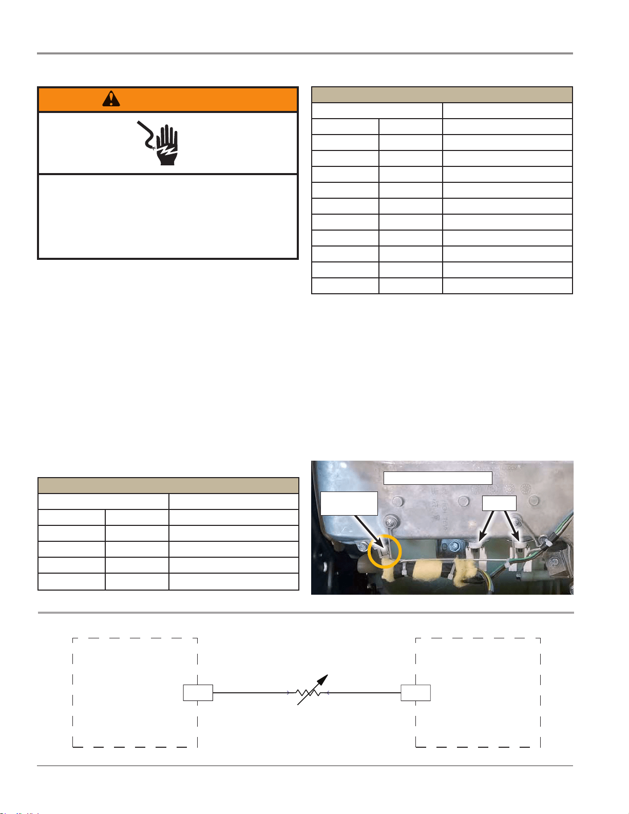
Figure 2 - Dry Temperature Sensor (NTC) Strip Circuit
DRY TEMPERATURE SENSOR (NTC)
ACU ACU
J14-1
J14-2
T
+5 VDC
DRY NTC
DRY TEMPERATURE SENSOR
77°F (25°C) = 20.0 k ohms
TCO’s
Dry Temp
Sensor (NTC)
Figure 1 - Dry NTC Location on Heater Channel Assembly
HEATER CHANNEL ASS’Y
Loading ...
Loading ...
Loading ...