Loading ...
Loading ...
Loading ...
COMPONENT TESTING
Whirlpool Smart All-In-One Washer & Dryer
n
3-13
For Service Technician Use Only
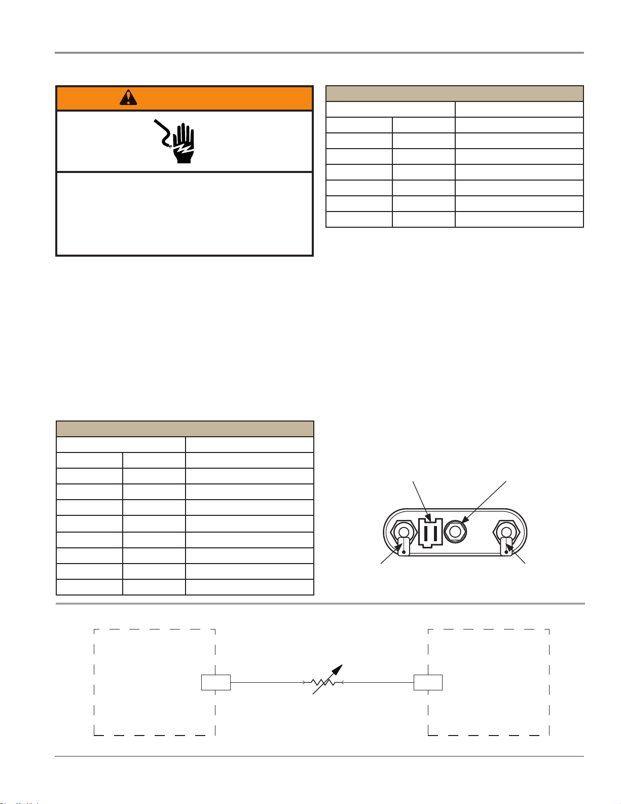
TEST #9: Wash Temperature Sensor
This test checks the temperature sensor, wiring, and ACU. This
test checks the temperature sensor, wiring, and ACU.
1. Unplug washer/dryer or disconnect power.
2.
Gently lay washer/dryer on its right side to access the
ACU. Remove AC shield and ACU cover.
3. Disconnect connector J14 from the ACU.
4. Using an ohmmeter, measure the resistance across pins 5
and 6 of temperature sensor connector J14.
THERMISTOR SENSOR RESISTANCE
Approx. Temperature Approx. Resistance
F° C° (KW)
-4 -20 197.3
14 -10 111.6
32 0 65.5
59 15 31.5
77 25 20.0
86 30 16.1
104 40 10.6
122 50 7.1
THERMISTOR SENSOR RESISTANCE
Approx. Temperature Approx. Resistance
140 60 4.9
158 70 3.4
176 80 2.4
194 90 1.8
212 100 1.3
248 120 0.7
302 150 0.3
¾ If the resistance is innite or close to zero, go to step 5.
¾ If it is within range, go to step 8.
5. Remove the rear panel to access the wash heang
element.
6. Disconnect the wash temperature sensor connector from
the heang element. See Figure 1.
7. Using an ohmmeter, measure the resistance across pins
1 and 2 of the wash temperature sensor (on the heang
element).
¾ If the resistance is within the specied range, the
sensor is good; replace the main harness.
¾ If the resistance is far out of range or open, replace the
temperature sensor.
8. If the preceding steps did not correct the temperature
sensor problem, replace the ACU.
¾ Unplug washer/dryer or disconnect power.
¾ Replace the ACU.
¾ Reassemble all parts and panels.
¾ Perform the Service Diagnosc Mode Tests on page 2-3
to verify repair.
Figure 2 - Wash Temperature Sensor Strip Circuit
WARNING
Electrical Shock Hazard
Disconnect power before servicing.
Failure to do so can result in death or
electrical shock.
Replace all parts and panels before operating.
WASH TEMPERATURE SENSOR
Figure 1 - Temperature Sensor
3$*(
¾
¾
¾
¾
¾
¾
¾
¾
¾
¾
¾
¾
¾
¾
¾
¾
¾
¾
Temperature Sensor
Heater Terminal Heater Terminal
Assembly Removal Nut
ACU ACU
J14-5
J14-6
T
+5 VDC
WASH NTC
WASH TEMPERATURE SENSOR
77°F (25°C) = 20.0 k ohms
Loading ...
Loading ...
Loading ...